Project 1 - Meshing of Floor Panel
OBJECTIVE
To extract the midsurface of the given floor panel, mesh the component using the given quality parameters and assign thicknesses.
QUALITY CRITERIA
| S.N | Quality Criteria | Value |
| 1 | Aspect Ratio | 5 |
| 2 | Skewness | 45 |
| 3 | Warping | 15 |
| 4 | Taper | 0.5 |
| 5 | Min. Length | 2 Units |
| 6 | Max. Length | 8 Units |
| 7 | Min angle Quad | 45 |
| 8 | Max angle Quad | 135 |
| 9 | Min angle Tria | 20 |
| 10 | Max angle Tria | 120 |
| 10 | Tria % | 10 |
MODEL IMAGE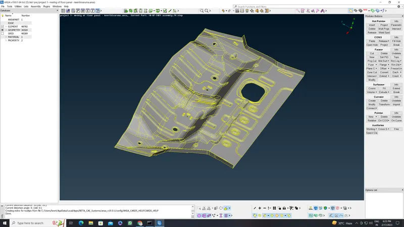
PROCEDURE
1. Firstly, we need to use the topo tool to take care of all the single cons and to ensure there are no free edges. It can be accessed via Faces > Topo in the topo module. All the cons are selected and the algorithm takes care of all the single cons.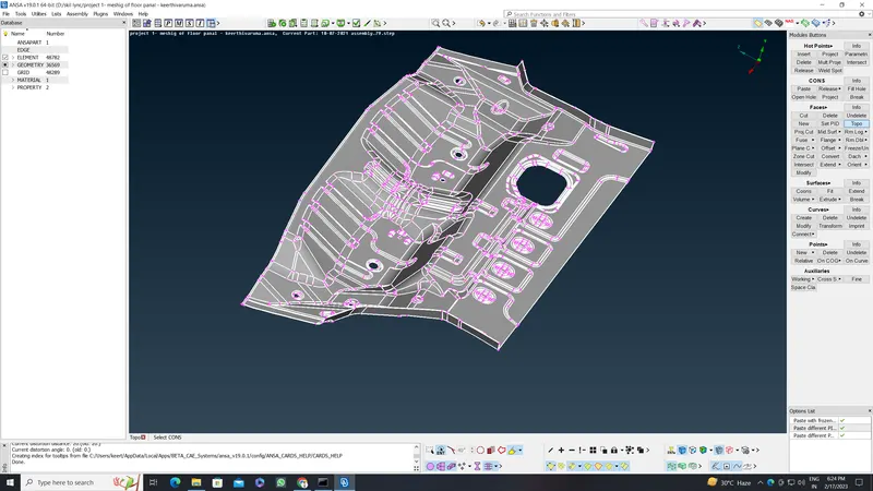
2. After that, as is the norm and before we carry out any other actions, we need to carry out a geometry check and fix all abnormalities. That is done via Checks > Geometry where we can execute checks of certain defects that can be selected from the menu and the algorithm looks for said defects. After detection, we can select all the defects and right-click > fix to fix them.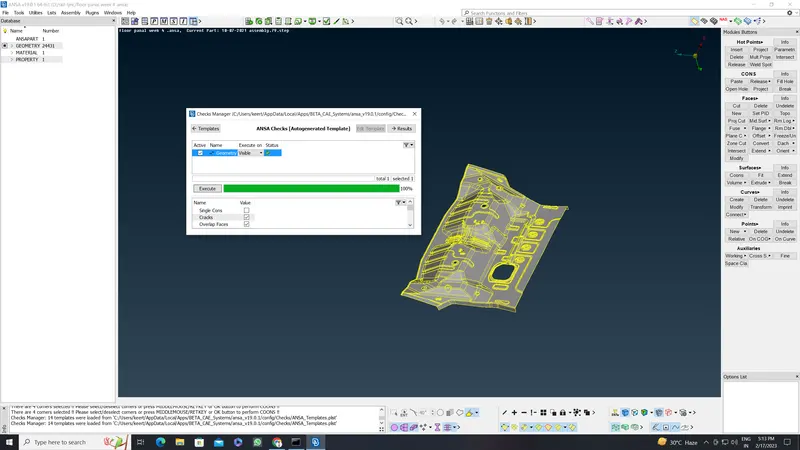
3. After orienting the model, using the Faces > Orient tool, we can go ahead and measure thicknesses of various regions in the component using the Measure tool from the top toolbar.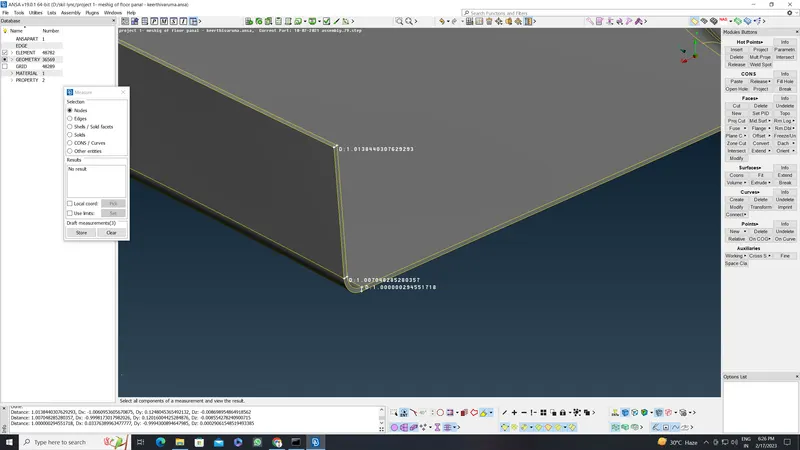
4. Now to generate the midsurfaces. There are multiple ways to do this. We shall be using the 'mid. suface' ad 'offset' for this component
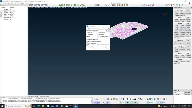
5. Now, having generated midsurfaces for the entire component, we can proceed with meshing. Before meshing, we need to set the target length (through perimeter > length). With that taken care of, we can assign the other parameters. This is done by accessing mesh parameters and quality criteria from the top toolbar.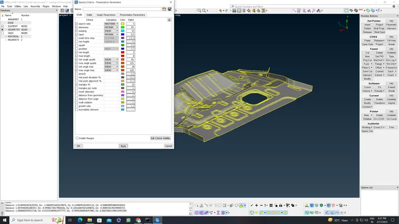
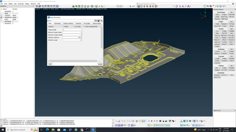
6. We can then start meshing the entire component (using batch mesh generation )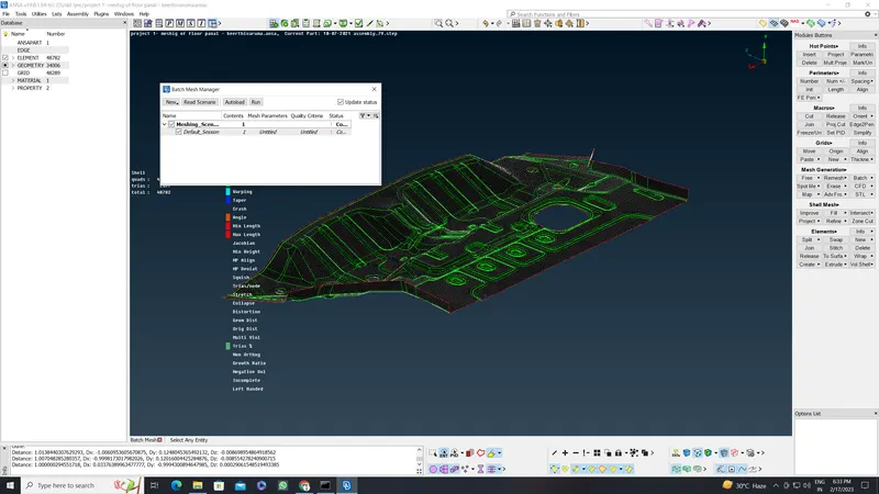
7. After that, we can make use of the reconstruct tool (Shell Mesh > Reconstruct) to generate a better mesh if the initial mesh is not satisfactory.
8. Sometimes, the reconstruct tool doesn't work in getting rid of some trias. Trias are okay but certain types of trias need to be avoided - like opposite trias or trias touching feature lines. Trias can be worked on using the swap, split, join and smooth tools. The first three are available in the 'Elements' section and the smooth tool is available in the 'Shell Mesh' section. The following example shows the tools in action:
9. Finally, after we finish meshing the entire component, as required, draw shell as solid needs to be activated. This can be done by going to Quality Parameters and accessing the Presentation Parameters tab.
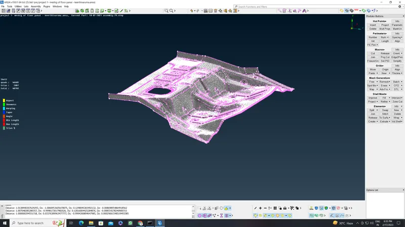
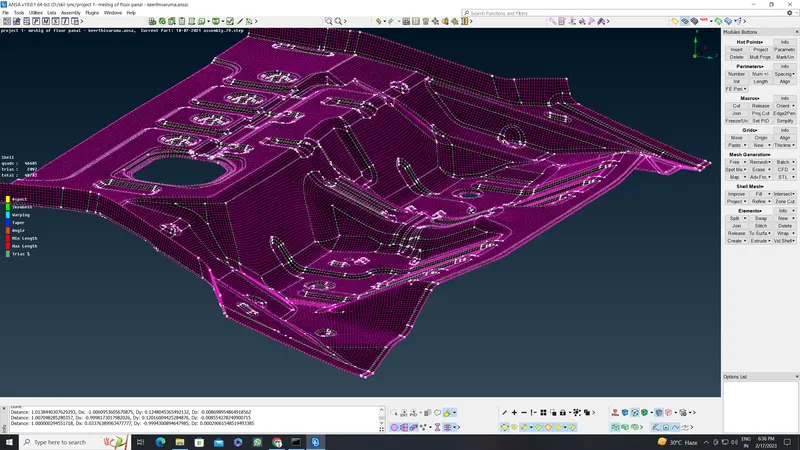
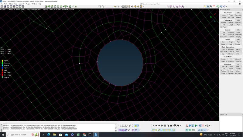
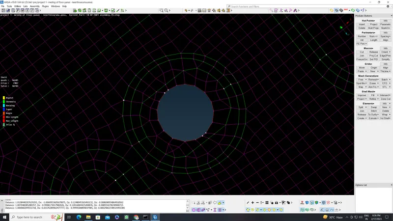
FINAL MESHED COMPONENT IMAGES
CONCLUSION
The given floor Panel model was midsurfaced and meshed as per given requirements and Ensured mesh flow was as good as possible.