Project 1 Mechanical design of battery pack
Aim: To develop a battery pack of 18KW using ANR26650M1-B cells along with their mechanical design.
Objectives:
Calculating the all parameters which are required for the build EV battery pack with given cell ANR26650M1-B
Calculating all Electrical parameters for 18 kWh Battery Pack.
Calculating all Physical dimensions for Battery Pack.
Finding the perfect enclosure for dimensions that we calculated for the Battery Pack.
Objective #1: Calculating the all parameters which are required for the build EV battery pack with given cell ANR26650M1-B
Battery pack capacity: 18 kW
As per the given information we are going to use A123’s high-performance Nano phosphate lithium iron phosphate (LiFePO4) battery technology delivers high power and energy density combined with excellent safety performance and extensive life cycling in a lighter weight, more compact package.
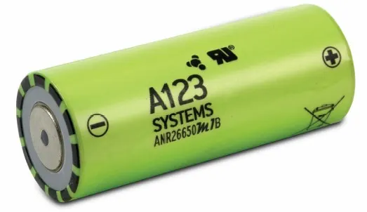
These cells have low-capacity loss and impedance growth over time as well as high usable energy over a wide state of charge (SOC) range, allowing our systems to meet end-of-life power and energy requirements with minimal pack oversizing
Data sheet of ANR26650M1-B cell:
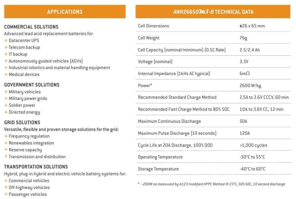
From above all parameters, we need to calculate parameters which are used for battery pack construction.
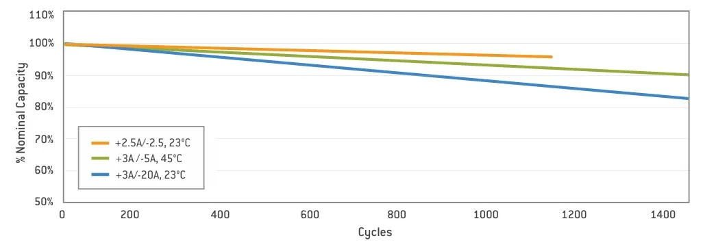
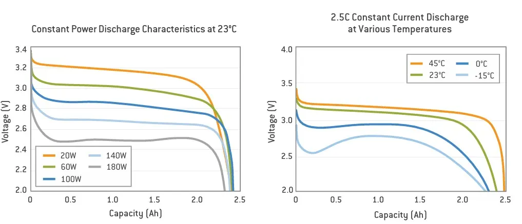
Cycle Life Performance, 100% DOD, Various Temperatures and Discharge Rates of cell:
Cell Parameters:
Battery energy :18 kWh (Given Requirement)
Nominal voltage :3.3 V
Cell capacity :2.5 Ah
Internal impedance :6 mohm
Cell weight :76 g
Cell Dimensions :26*65 mm
Operating temperature :(-30°C to 55°C)
Storage Temperature :(-40°C to 60°C)
Power :2600 W/kg
Rmd. Standard Charge Method :2.5A to 3.6V CCCV, 60 min
Rmd. Fast Charge Method to 80% SOC :10A to 3.6V CC, 12 min
Maximum Continuous Discharge :50A
Maximum Pulse Discharge (10 seconds) :120A
Cycle Life at 20A Discharge, 100% DOD :>1,000 cycles
EV design - Battery calculation:
Assumptions:
Battery energy = 18 kwh
Voltage (to run the vehicle) = 400V
Number of cells (N) : Energy / (Nominal voltage * Cell Capacity)
Number of cells (N) :18000 / (3.3*2.5)
Number of cells (N) :2182
We need a minimum of 2182 cells to get 18 kWh energy, now based on that, we need to decide configuration – series and parallel.
In series configuration “capacity remains the same and voltage will be the sum of individual cell voltage”. In a parallel configuration” the voltage remains the same and capacity accumulates”.
And we assumed 400 Volts are need to run the vehicle.
The nominal voltage of one cell is 3.3 V
Number of series cells required to produce 400 V (Ns) = Voltage required / Nominal voltage of one cell
Number of series cells Ns :400 / 3.3
Number of series cells Ns :121.21 ≈ 122 Nos
122 cells are connected in series will generate 400 voltage and the capacity of the whole module will be 2.5 Ah since it will be connected in series.
Now we need to find the number of cells which will be connected in a parallel configuration
Np (cell in parallel) = total cell / Ns
Number of Parallel cells Np :2182 / 122
Number of Parallel cells Np = 17.8 ≈ 18 Nos
Hence, we take 18 cells for each parallel row, although it is exceeding the required capacity, that is negligible.
Cell architecture = 122 Series and 18 Parallel = 122S18P
Battery capacity:
We know parallel configured cell multiplies individual cell capacity so,
Battery Capacity = parallel cell row*individual cell capacity
Battery Capacity = 18 * 2.5
Battery Capacity :45 Ah
Module capacity:
The required battery pack combination is 122S18P
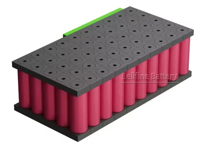
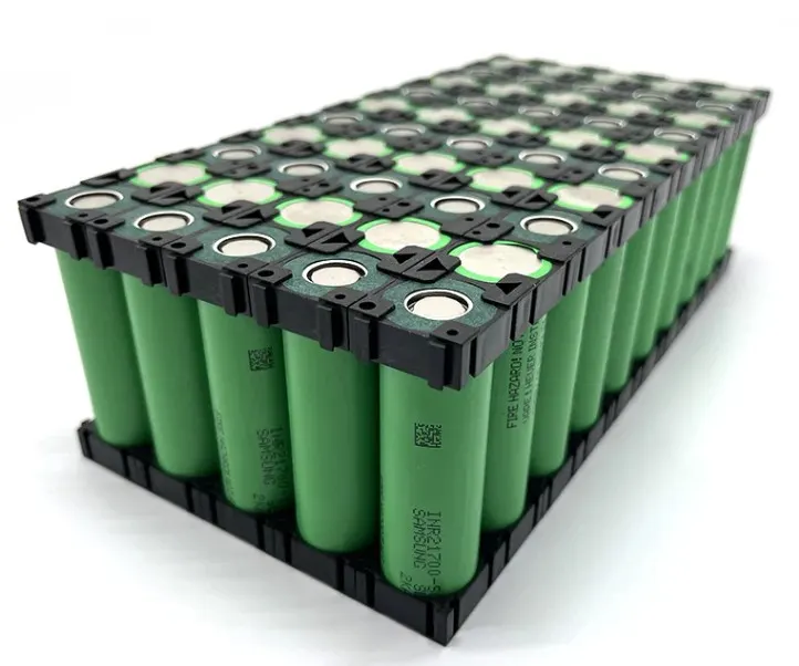
For this we decided to choose 10 series and 5 parallel module connection.
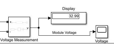
Each 10S5P configuration Module Voltage capacity = 10*3.3 = 33 V
Each 10S5P configuration Current Module capacity = 5*2.5 = 12.5 Ah
So, total capacity of 1 module is = 33 * 12.5 = 412.5 Wh
Cell Energy
Cell Energy : Cell Capacity (Ah) × Cell Voltage (V)
: 2.5 × 3.3
Cell Energy : 8.25 Wh
The value of a single cell is used to calculate the total energy of the battery pack.
Single Cell Energy Density
Volumetric energy (Wh/m3) = Single Cell Energy / Volume of each cell
= 8.25 Wh / 0.0000344929 m3
=2, 39,179.6572 Wh / m3
Single Cell Energy Density is 239.18 KWh / m3
Assume:
Vehicle Range
= 320 KM
Battery Pack capacity = 18 kWh or 18000 Wh
Now,
We will calculate per km average energy = 18000/ 320
= 56.25 Wh/km
Therefore,
Battery Pack total energy : Average
energy x km
: 56.25 x 320
Battery Pack total energy :18000 Wh or 18.00 kwh
Total no of Module:
With 10S5P battery modules, we need following no of battery module
Capacity of 1 module: 412.5 Wh
Total No of module needed to form a 18kw battery pack,
Total no of module = Battery pack capacity / Capacity of 1 module
Total no of module = 18000 / 412.5
Total no of module = 43.63 ≈ 44 no’s
Weight Calculation:
Weight of one cell = 76 g = 0.076kg
Weight of one module = 50 * 0.076
Weight of one module = 3.8 Kg
Battery pack cell weight = 44 * 3.8
Battery pack cell weight = 167.2 kg
Simulink Model for 10S5P battery Module:
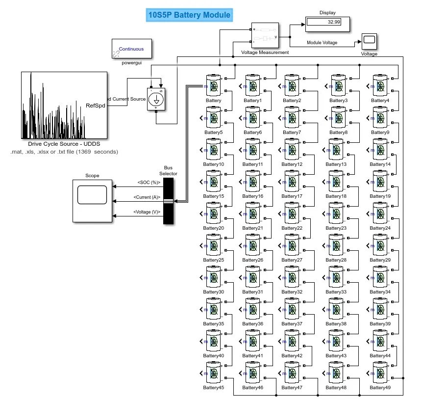
Output:
# Cell Voltage, Current and Cell SOC results
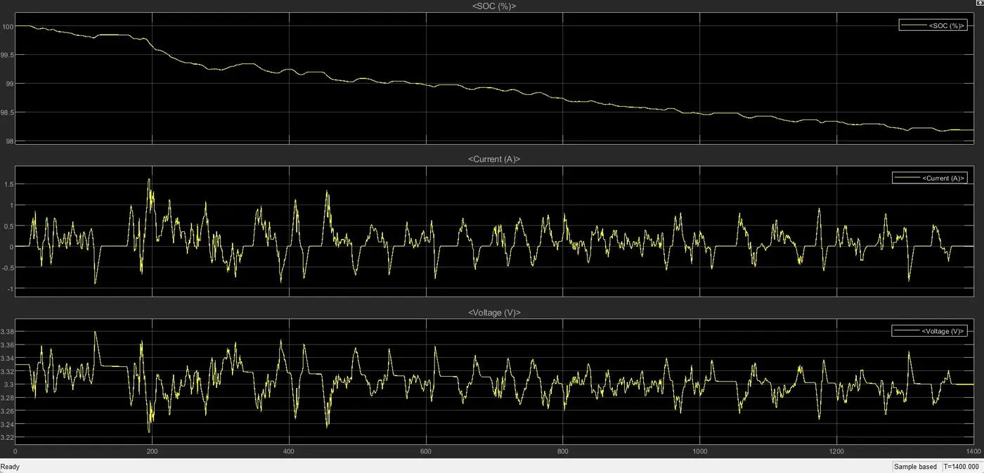
# Battery Module:
To connect 3.3 full charge voltage cell in series (10 S) the voltage across the cell will be 33V
From below results we could see our theoretical calculated voltage matching with the graph results
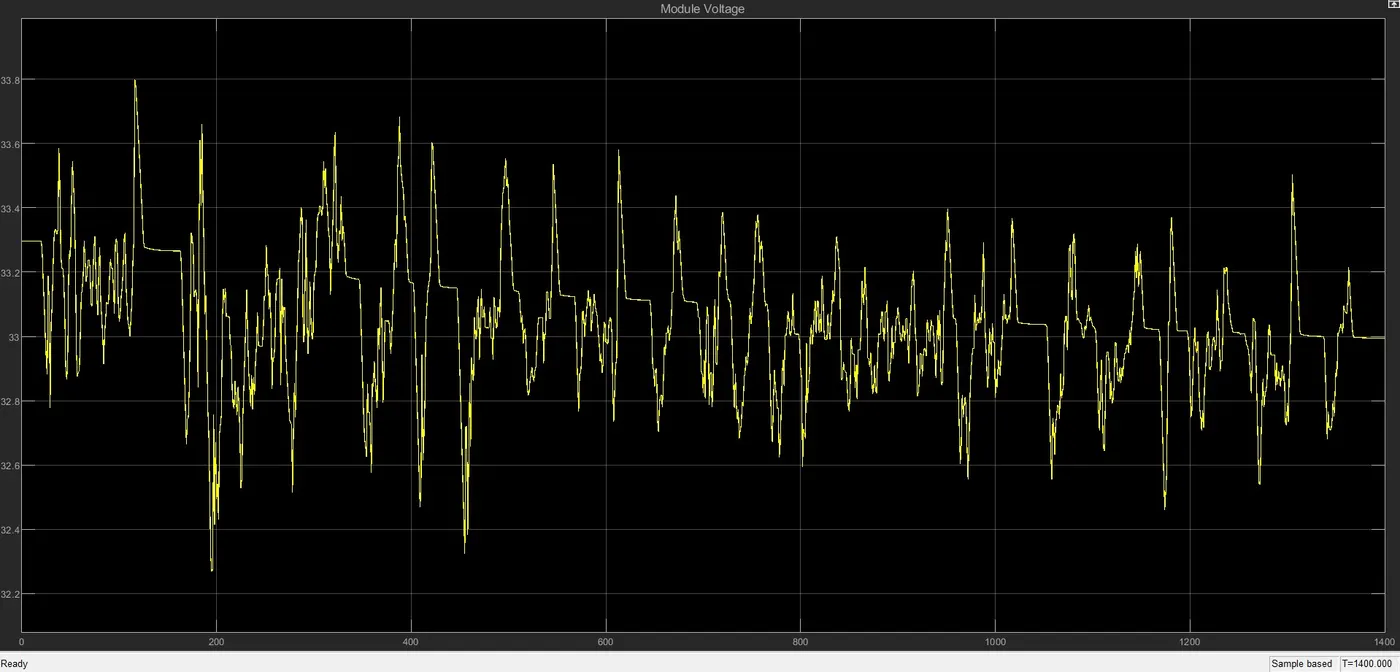
The 10S5P connection of ANR26650M1-B cell is shown below.
Battery single module enclosure pack size:
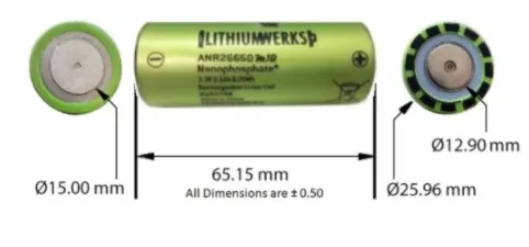
ANR26650 cell has 26mm diameter and 65mm height. On the basis of that we need to decide battery size of battery casing which is total battery pack.
Length of casing (L) = No. of cell in series connection * (Diameter of single cell + cell spacing)
L = 10*(26+4)
L = 300 mm
Total Length of single module = 300mm (0.3 meters).
Breadth of casing (B)
Similarly for width, we are assuming the parallel connection along the width of our pack again to keep the design simple.
Width of battery pack = No. of cells in parallel * (Diameter of single cell + cell spacing)
B = 5*(26+4)
Total Width of single module = 150mm (0.15 meters).
Height of casing (H):
Now that we have length and breadth we need height of the pack, which can be determined by adding the height of cell with the other parameter such as cell holder, metal strip and some space for wiring and cooling functions, we will assume approximately 35mm for all these parameters. So now the height of battery pack is,
Height of battery pack = (Height of individual cell + 35) = 65 + 35 = 100mm
Total Height of single module = 100mm (0.1meters)
Area of single module:
We have got the length, breadth and height of single module. With these data we can calculate the area and volume as follows,
We selected the 10S5P battery module for our battery pack, Obvoiusly it is going to be a rectangular shape
Area of battery module : Length of battery module * width of battery module
: 300 * 150
Area of battery module = 0.045 m2
Area of Battery Pack:
We have 44 – 10S5P such module to full our battery pack capacity requirement
So, the area of the battery pack will be,
Area of battery pack = Area of battery module * No of Modules
= 0.045 * 44
Area of battery pack = 1.98 m2
Volume of Battery Pack:
volume of battery pack = area of battery pack * height of battery pack
= 1.98 * 0.1
volume of battery pack = 0.198 m3
Battery Pack:
A battery consists of one or more electrochemical cells (battery cells) which are converting chemical energy into electrical energy (during discharging) and electrical energy into chemical energy (during charging).
The type of elements contained within a battery and the chemical reactions during discharging-charging events define the chemistry of a battery. A battery cell consists of five major components: electrodes – anode and cathode, separators, terminals, electrolyte and a case or enclosure
Individual battery cells are grouped together into a single mechanical and electrical unit called a battery module.
The modules are electrically connected to form a battery pack.
There are several types of batteries (chemistry) used in hybrid and electric vehicle propulsion systems but we are going to consider only Lithium-ion cells. The main reason is that Li-ion batteries have higher specific energy [Wh/kg] and specific power [W/kg] compared with other types.
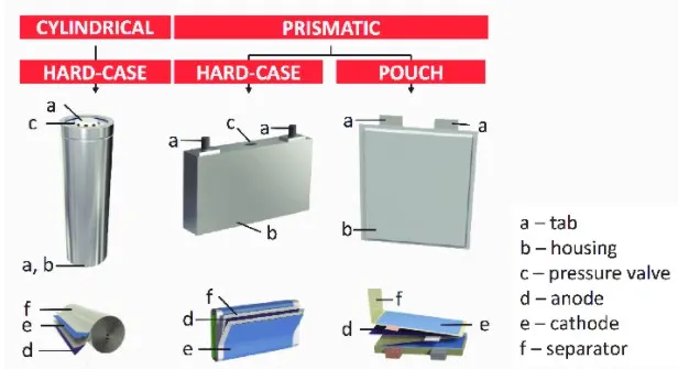
Ev uses mainly 3 types of cells: Cylindrical, prismatic and pouch.
Prismatic cell:
Prismatic cells are made up of many positive and negative electrodes sandwiched together leaving more possibility for short circuit and inconsistency. The higher capacity makes it difficult for the BMS to protect each cell from over charging and dissipating heat.
Cylindrical cell:
A cylindrical cell is a cell enclosed in a rigid cylinder can. Cylindrical cells are small and round, making it possible to stack them in devices of all sizes. Unlike other battery formats, their shape prevents swelling, an undesired phenomenon in batteries where gasses accumulate in the casing.
Cylindrical cells are commonly found in medical instruments, laptops, e-bikes, and power tools. These batteries are also used in Tesla vehicles. Other EV manufacturers employ prismatic cells
Battery Pack construction:
There are 3 steps for the construction of the battery pack.
1) Battery holding and providing the spacing between the batteries.
2) Connecting the batteries with the strips (Series or Parallel)
3) Making and manufacturing the battery enclosure housing with the thermal management system and BMS
1) Holding and spacing:
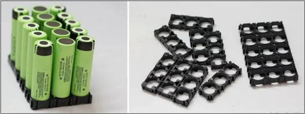
Each of the cells are now need to be connected so that it could form a big battery module.
So this holdes are very importatnt to provide the gapping between the battery and holding the battries in the correct manner.
The cells has a vent at the end cap of the cell. And should not be covered by any mechanical means. Blocking the cell vent and then sufficiently abusing the cell so as to built the pressure in cell. There must be minimum of 1mm spacing between each cells to allow the vent to open under the fault condition.
Holders will make it easy to palette contact plate between the cells.
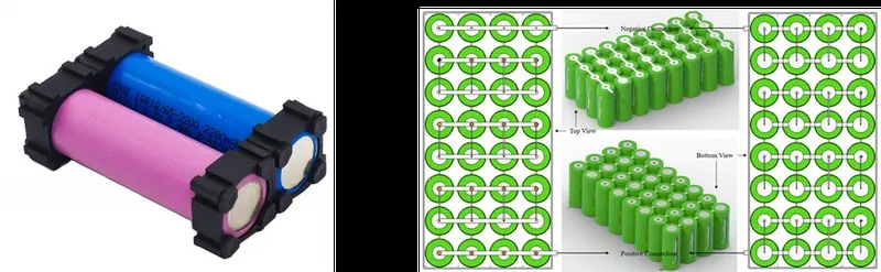
2) Connecting the cells:
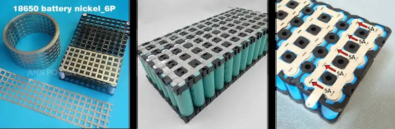
When the cells are placed in the holders, then the cells need to be connected in the proper manner in series or parallel to get the desired results.
Usually, a Nickle strip is used between the cells to make the contact.
Nickel strip is generally used in battery building.
Its due to its efficiency of usage in spot welding and soldering as well its high corrosion resistance over time.
It has good properties and excellent resistance to many corrosive environments.
The pure nickel will never get rust after it applied to battery packs.
It won’t affect the current transfer between batteries. Pure nickel strips are the material you want, but many vendors swap out it for nickel-plated steel strips, which are poorer and have greater resistance – not suitable for most battery projects. 100% pure nickel strip.
verify all of our strips to assure that you are getting the high-quality pure nickel. It also solders incredibly quickly, so you can weld them onto your existing busbar connections to raise the supply of current you can pull through the busbars. The benefits are nearly limitless!
3)Battery enclosure and thermal management of battery and BMS
The battery enclosure is the final protection of the battery.
So, the battery enclose must be very strong and light in weight.
In the case of any accident the batteries have the tendency of catch fire if it get leaked during the car crash, so the battery model is enclose in a very strong enclosure due to the safety.
The weight should be less so we can get the best possible range.
In this metal housing there is a temperature management system provided to cool and heat the batteries when there is a need to get the best performance of the batteries.
There a several numbers of models connected in series and parallel to build a entire battery pack.
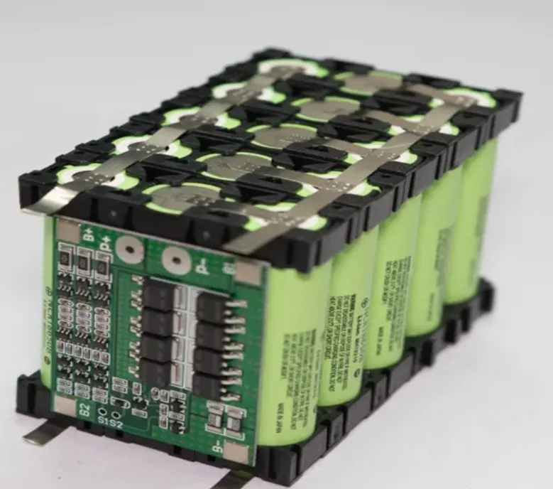
BMS:
A battery management system (BMS) is an electronic system that manages a lithium battery pack and the main functionalities are
- Monitors all of the parallel groups in the battery pack and disconnect it from the input power source when fully charged
- Balance all the cells voltage equally
- Doesn't allow the pack from over-discharged
Conclusion:
We studied and build the 18Ah battery capacity for ANR26650M1-B. Initially we started with cell calculation, then we will do Battery Pack assumptions. Based on the assumptions, we have to do Battery pack calculations. We calculated the Cell Dimensions, area and volume requirement. Finally, we considered the different form factor for battery pack construction with proper enclosure and insulation