Project 1 Mechanical design of battery pack
AIM:
The project is to design a battery pack with a capacity of 18 kWh using ANR26650M1-B cells. The battery pack will be arranged in a 12S6P configuration, with a total of 72 cells.
For the battery pack, we will assume the following:
Cell: ANR26650M1-B
Battery pack capacity: 18 kWh
Number of cells: 72 (arranged in a 12S6P configuration)
The nominal voltage of a single cell: 3.3 V
The nominal voltage of the series connection: 39.6 V (12 x 3.3 V)
Single-cell capacity: 2.5 Ah
Max pulse charge current (C rate): 5 C
Max continuous charge current (C rate): 3 C
Mass of single cell: 85 g
The volume of a single cell: 34.4 cm^3
PROJECT OVERVIEW:
The project aims to design an 18-kWh battery pack using ANR26650M1-B cells in a 12S6P configuration, with a total of 72 cells. The ANR26650M1-B cell is a lithium iron phosphate (LiFePO4) cell with a nominal voltage of 3.3V and a capacity of 2.5Ah, which has a high energy density and long cycle life. The charging process for a lithium iron phosphate battery pack typically involves three stages: constant current (CC) charging, constant voltage (CV) charging, and trickle charging. During discharge, the battery pack supplies a current to a load until the voltage of the battery pack drops below a predetermined level. The 12 cells will be connected in series to increase the nominal voltage of the battery pack to 39.6 V, and the 6 groups of 12 cells each will be connected in parallel to increase the total capacity of the battery pack. The cells will be spot welded together using a resistance spot welding technique.
CALCULATIONS:
Single Cell Energy (Wh) = 2.5 Ah x 3.3 V = 8.25 Wh
Single Cell Energy Density:
a. Volumetric energy (Wh/m^3) = 8.25 Wh / 34.4 cm^3 = 0.240 Wh/cm^3
b. Gravimetric energy (Wh/kg) = 8.25 Wh / 0.085 kg = 97.06 Wh/kg
Number of cells connected in series = 39.6 V / 3.3 V = 12 cells
Energy for battery pack (Wh) = 12 cells x 8.25 Wh = 99 Wh
Number of cells connected in parallel = 18,000 Wh / 99 Wh = 181.82 ≈ 182 cells
Battery pack total energy (Wh) = 182 cells x 8.25 Wh = 1,500.5 Wh
Battery pack capacity = 182 cells x 2.5 Ah = 455 Ah
Total number of cells for battery pack = 12S6P configuration = 12 x 6 = 72 cells
Mass of battery pack = 72 cells x 0.085 kg = 6.12 kg
Total volume of the battery pack = 72 cells x 34.4 cm^3 = 2476.8 cm^3 = 2.48 L
Cell peak current (A) = 5 C x 2.5 Ah = 12.5 A
Battery pack peak current (A) = 12.5 A x 182 cells = 2275 A
Battery pack peak power (W) = 2275 A x 39.6 V = 90,090 W ≈ 90 kW
Cell continuous current (A) = 3 C x 2.5 Ah = 7.5 A
Battery pack continuous current (A) = 7.5 A x 182 cells = 1365 A
Battery pack continuous power (W) = 1365 A x 39.6 V = 54,054 W ≈ 54 kW
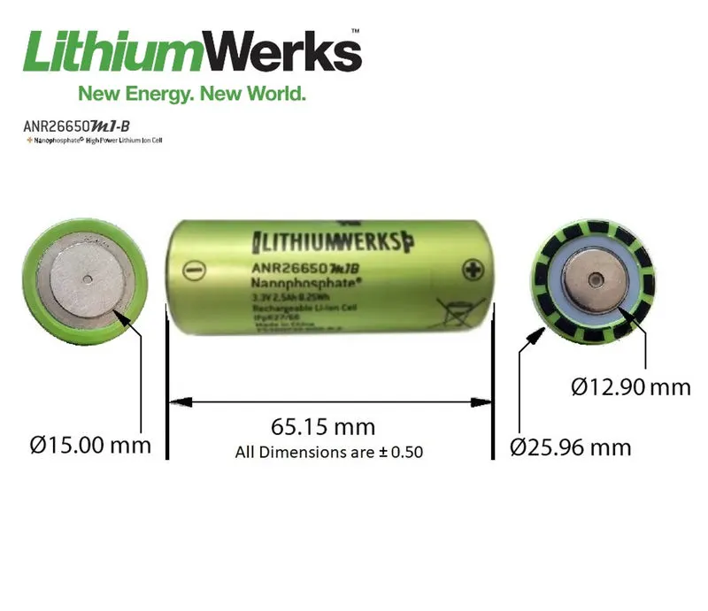
Cell:
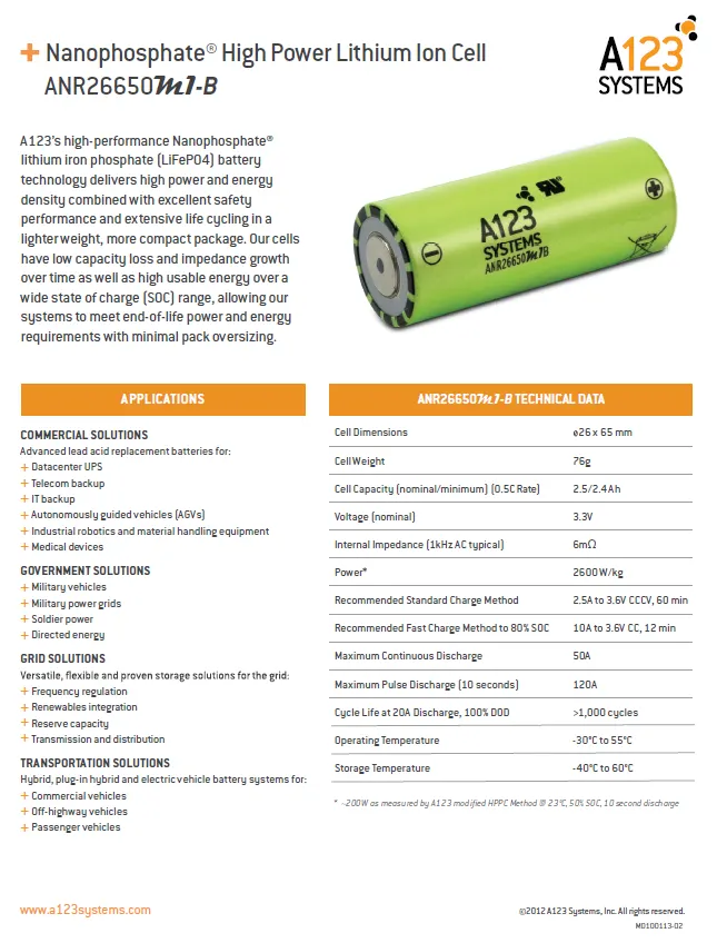
The ANR26650M1-B cell is a lithium iron phosphate (LiFePO4) cell with a nominal voltage of 3.3 V and a capacity of 2.5 Ah. It has a high energy density and can deliver high power output. It also has a long cycle life and is considered to be a safe and reliable battery chemistry.
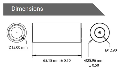
| Cell dimensions | 26*65 mm |
| Cell weight | 76g |
| Cell Capacity(nominal/minimum) (0.5C rate) | 2.5/2.4 Ah |
| Voltage(nominal) | 3.3V |
| internal impedance | 6 mOhm |
| power | 2600W/kg |
| Recommended Standard charging method | 2.5A to 3.6V CCCV,60 min |
| Recommended Standard charging method to 80% SOC | 10A to 3.6v CC,12 min |
| maximum continuous discharge | 50A |
| maximum pulse discharge | 120A |
| cycle life at 20A discharge (10 seconds) |
>1000 cycles |
| operating temperature |
-30c to 55c |
| storage temperature |
-40c to 60c |
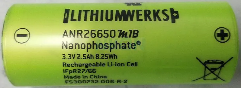
The ANR26650M1-B is a lithium iron phosphate (LiFePO4) cell that has a nominal voltage of 3.3V and a capacity of 2.5Ah. A battery pack made up of ANR26650M1-B cells can be used in various applications, including electric vehicles, energy storage systems, and backup power systems.
Charging:
When charging a battery pack made up of ANR26650M1-B cells, it is important to use a charger that is specifically designed for lithium-iron-phosphate cells. Charging the battery pack with a charger that is not compatible with this chemistry can result in damage to the battery pack or, in extreme cases, a fire.
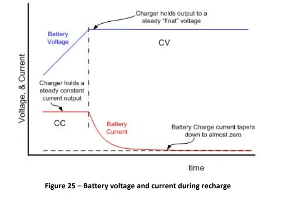
The charging process for a lithium iron phosphate battery pack typically involves three stages: constant current (CC) charging, constant voltage (CV) charging, and trickle charging. During the CC charging stage, the charger supplies a constant current to the battery pack until the voltage of the battery pack reaches a predetermined level. During the CV charging stage, the charger maintains a constant voltage while the current decreases. Finally, during trickle charging, the charger supplies a low current to maintain the battery pack's charge.
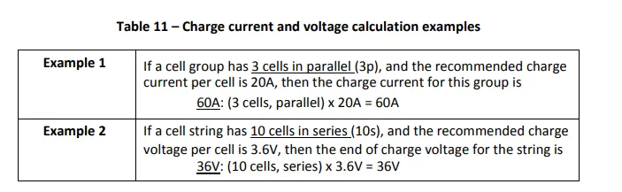
Charger Limits
When charging or recharging Lithium Werks cells in a battery pack, the charger should limit its output current and
voltage to match that of the battery pack configuration. During a recharge, the charger shall apply a constant
current (CC) charge followed by a constant voltage (CV) charge. In addition, the charger shall cease charging
when either:
• Any one cell in the series string, has exceeded its maximum recommended charge voltage, or
• The temperature measured in the pack has gone outside the recommended range for charging.
Discharging:
During discharge, the battery pack supplies a current to a load until the voltage of the battery pack drops below a predetermined level. It is important to ensure that the discharge current is within the rated discharge current of the battery pack to prevent damage to the cells. In general, the discharge current should not exceed the maximum continuous discharge current specified for the battery pack.
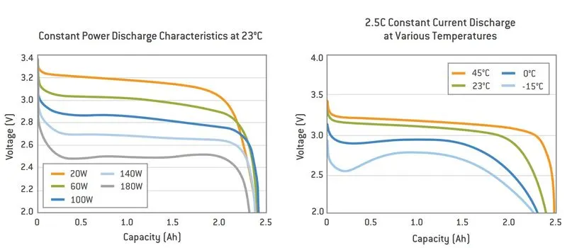
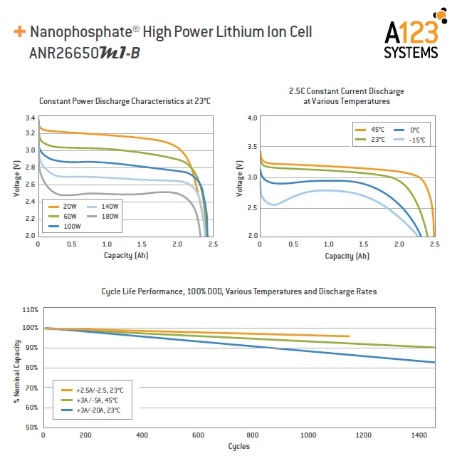
Lithium iron phosphate battery packs like ANR26650M1-B have a relatively flat discharge curve, which means that their voltage remains relatively constant until they are almost fully discharged. This allows for more efficient use of the battery pack's capacity compared to other battery chemistries, such as lead-acid batteries. Additionally, lithium iron phosphate battery packs have a longer cycle life compared to other chemistries and are considered to be safer and more environmentally friendly.
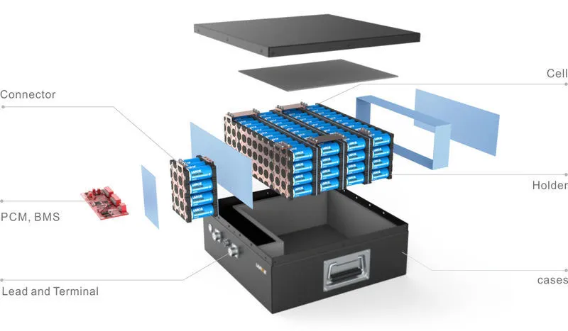
Battery:
The battery pack will be made up of 72 ANR26650M1-B cells arranged in a 12S6P configuration. The total energy capacity of the battery pack will be 18 kWh, which is the product of the number of cells, their capacity, and their nominal voltage.
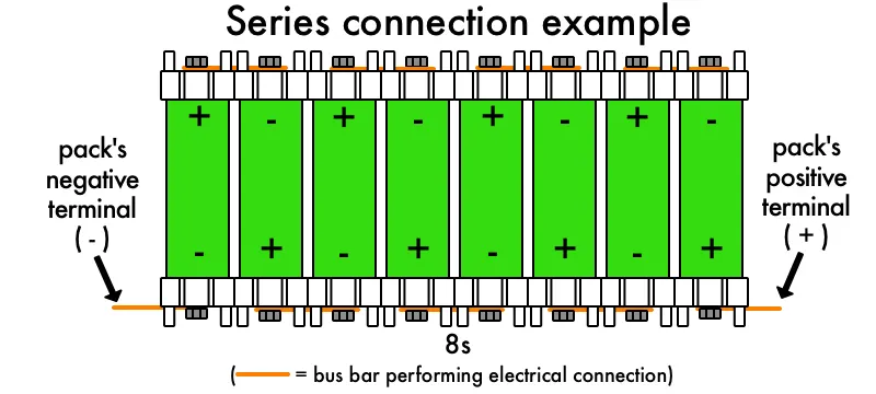
Series connection:
The 12 cells will be connected in series to increase the nominal voltage of the battery pack to 39.6 V. The voltage of the battery pack will be the sum of the voltages of the individual cells connected in series.
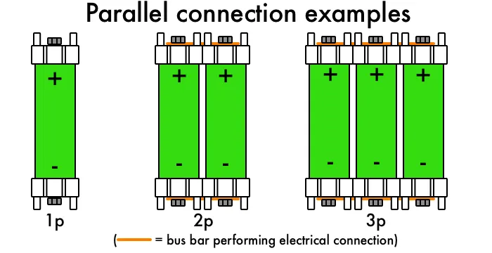
Parallel connection:
The 6 groups of 12 cells each will be connected in parallel to increase the total capacity of the battery pack. The capacity of the battery pack will be the product of the capacity of a single cell and the number of cells connected in parallel.
welding:
The cells will be spot welded together using a resistance spot welding technique. This is a common technique used in battery pack manufacturing to join the cells in series and parallel connections.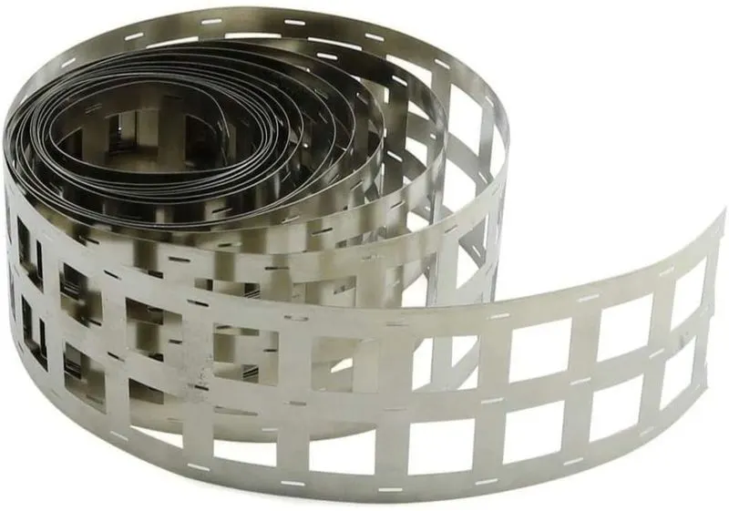
Cell Electrical connectors and joining Technologies
for the internal connection, nickel strips are used. Nickel is an essential component for the cathodes of many secondary battery designs. Nickel strip is generally used in battery building. Its due to its efficiency of usage in spot welding and soldering as well as its high corrosion resistance over time. It has good properties and excellent resistance to many corrosive environments. Pure nickel will never rust after it is applied to battery packs. Nickel strips are used as battery connectors because they have 20-30% more conductivity than other materials
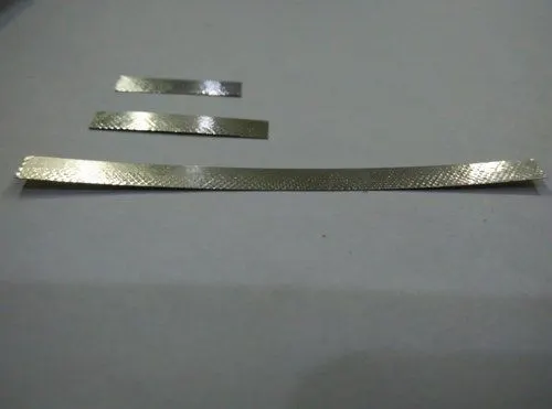
Nickel Strips
Nickel strip is generally used in battery building. It's due to its efficiency of usage in spot welding and soldering as well as its high corrosion resistance over time. It has good properties and excellent resistance to many corrosive environments. Pure nickel will never rust after it is applied to battery packs. It won’t affect the current transfer between batteries.
Pure nickel strips are the material you want, but many vendors swap it for nickel-plated steel strips, which are poorer and have greater resistance – not suitable for most battery projects.
100% pure nickel strip. verify all of our strips to assure that you are getting a high-quality pure nickel. It also solders incredibly quickly, so you can weld them onto your existing busbar connections to raise the supply of current you can pull through the busbars. The benefits are nearly limitless!
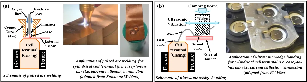
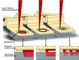
Laser welding and spot welding are two commonly used techniques for joining metals together, including in battery pack manufacturing.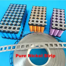
Laser welding involves the use of a highly focused laser beam to melt and join two metal parts together. The laser beam heats the metal to its melting point and creates a welding pool, which then solidifies and fuses the two parts together. Laser welding is a fast and precise technique that can produce strong and high-quality welds. It is commonly used in industries such as automotive, aerospace, and electronics.
Spot welding, on the other hand, is a resistance welding technique that involves the use of an electric current to create heat and join two metal parts together. The parts to be welded are held together between two copper electrodes, and an electric current is passed through the electrodes and the metal parts. The resistance to the electric current generates heat, which melts and joins the metal parts together. Spot welding is commonly used in battery pack manufacturing because it is a fast and efficient technique for joining metal parts, especially for high-volume production.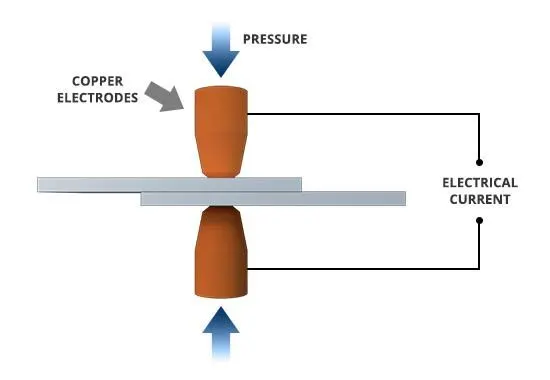
Resistance welding(Spot welding)
Resistance welding relies on the electrical resistance at the metal interface to cause localized heating and fusion of materials. The pressure exerted by the electrodes, through which the electrical current flows, holds the workpieces to be welded in close contact before, during, and after the welding cycle Resistance welding process is very fast and can be easily automated. It has a wide application in the automotive, electronics, and heavy industries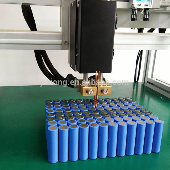
In battery pack manufacturing, both laser welding and spot welding are used to join the individual battery cells together in series and parallel connections. Spot welding is commonly used for joining the thin metal tabs that connect the battery cells together, while laser welding may be used for joining thicker metal parts or for precision welding of certain components. The choice of welding technique depends on the specific requirements of the battery pack design and the manufacturing process.
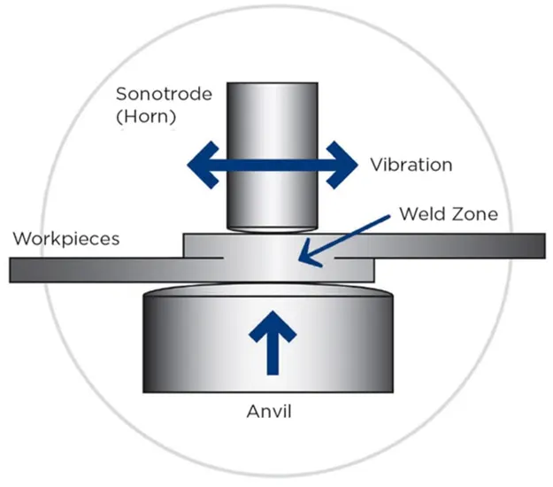
Ultrasonic welding
Ultrasonic metal welding is a process in which a high frequency, usually 20 kHz or above, of ultrasonic energy is used to produce oscillating shears to create solid-state bonds between two sheets clamped under pressure. Ultrasonic welding can be used to join a wide range of types of metal sheets or thin foils. The lateral forces, generated at high frequency, break down contamination and produce an atomic bond between metal interfaces at elevated temperatures. In contrast to traditional fusion welding processes, ultrasonic welding has several inherent advantages derived from its solid-state process characteristics. The main advantage of ultrasonic welding is that it works well for dissimilar materials and multiple sheets, which is crucial for cell joining as well as for battery tab joining [24]. Ultrasonic welding is attractive for battery manufacturing because of its low temperature and relatively good performance for Al, Cu, and other highly conductive materials.
Summary of cell joining method
|
Joining methods |
Advantages |
Disadvantage |
|
Resistance welding |
|
|
|
Laser welding |
|
|
|
Ultrasonic welding |
|
|
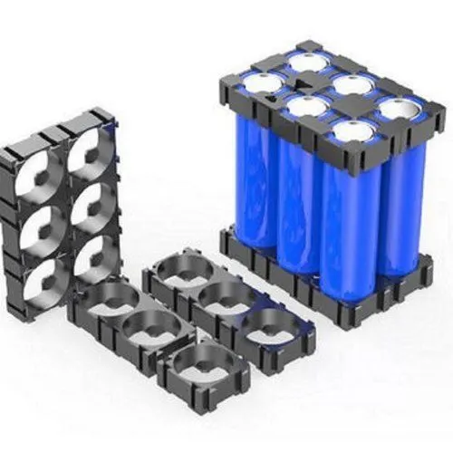
Holders:
The battery pack will be housed in a plastic enclosure that will have holders to secure the cells in place and provide electrical insulation. The holders will also help in dissipating the heat generated during operation.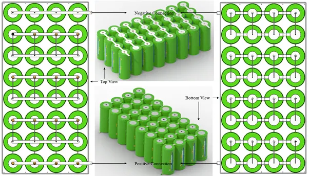
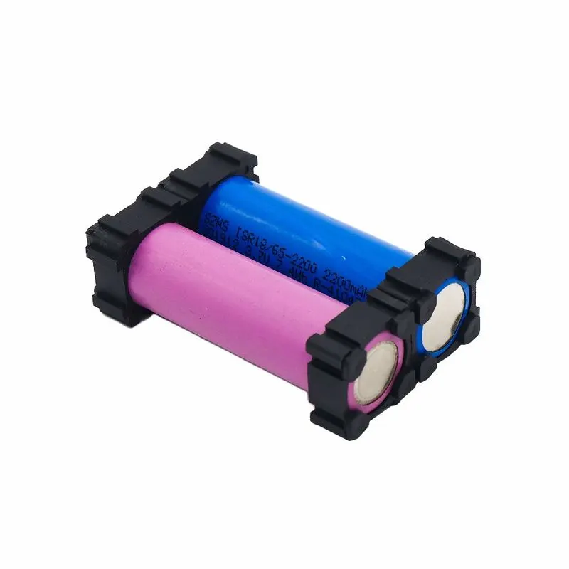
The primary function of a battery holder is to keep cells fixed in place safely and securely while conveying power from the batteries to the device in question. External connections on battery holders are most often made by contacts either with pins, surface mount feet, soldered lugs, or via a set of wire leads.
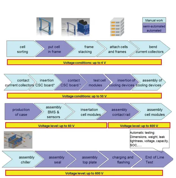
Assembly of the battery pack:
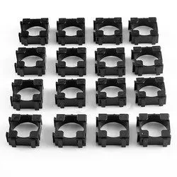
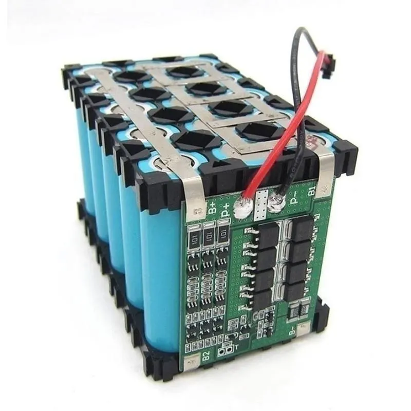
step 1:
start with snapping the square holder together as per our number of cells. and put the insulating gasket on the positive side of the cell.
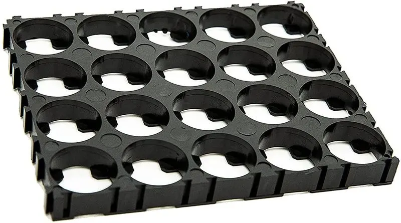
Step 2:
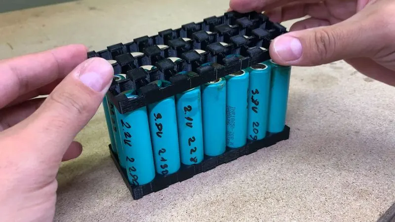
Now place the cells in the cell holder matrix. After loading all cells put the second cells connector block on another side.
Step 3:
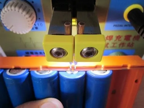
connecting the cells using the nickel strip. We can use the H type of nickel strip or a single nickel strip. using the nickel strip series and parallel connections are made.
As above mentioned, we have different types of joining methods we can prefer resistance (spot) welding as it takes less cost as per the other welding method and it is a fast process
step 4 :
After connection, stick PVC sink film to the cell. Connect the Balancing wire pin to BMS and glue it to the side of the battery pack with BMS.
Step 5:
now put the battery pack in the housing which is made as per the above calculation.
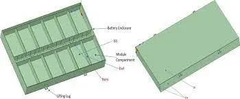
Battery cover:
The battery pack will have a cover made of plastic or metal to protect the cells and provide mechanical strength to the pack. The cover will also have a vent to release any gases generated during operation.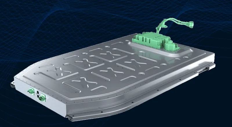
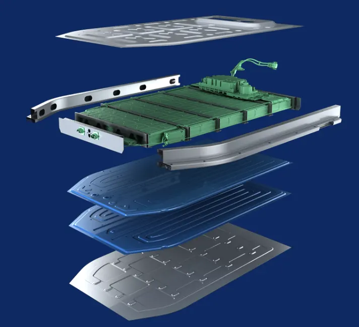
Battery management system:
The battery pack will have a battery management system (BMS) that will monitor the voltage, current, temperature, and state of charge of the battery pack. The BMS will also protect the battery pack from overcharging, over-discharging, and over-temperature conditions.
The LithiumWerks ANR26650M1-B is a cylindrical lithium iron phosphate (LiFePO4) battery cell with a nominal voltage of 3.3 volts and a capacity of 2.5 Ah. Here are some additional details about this battery:
Chemistry: Lithium iron phosphate (LiFePO4)
Nominal voltage: 3.3 volts
Capacity: 2.5 Ah
Energy density: 120 Wh/kg
Cycle life: > 3,000 cycles at 80% depth of discharge (DoD)
Operating temperature range: -20°C to +60°C
Dimensions: 26.2 mm diameter x 65 mm length
Weight: 85 grams
Lithium iron phosphate batteries are known for their high cycle life, excellent safety profile, and low risk of thermal runaway or combustion. They are commonly used in applications such as electric vehicles, energy storage systems, and backup power supplies. The ANR26650M1-B is designed for high power and high energy applications where a reliable and durable battery is needed.
The LithiumWerks ANR26650M1-B battery can be used in a wide range of applications, including:
Electric vehicles: The high power and energy density of these batteries make them well-suited for use in electric vehicles such as cars, trucks, buses, and motorcycles.
Renewable energy storage: Lithium iron phosphate batteries are commonly used in renewable energy storage systems such as solar and wind power plants, where they can store energy during excess generation and discharge it during periods of high demand.
UPS systems: Uninterruptible power supply (UPS) systems use batteries to provide backup power in the event of a grid outage or other power failure.
Marine and RV applications: The durability and safety of these batteries make them well-suited for use in marine and RV applications where space and weight are a concern.
Regarding efficiency, the ANR26650M1-B has a relatively high energy density of 120 Wh/kg and a long cycle life of over 3,000 cycles at 80% depth of discharge. There are other lithium iron phosphate batteries on the market with similar or higher energy densities, but the cycle life and safety features of the ANR26650M1-B make it a popular choice for many applications.
There are several possible ways to make this battery more efficient, including:
Improving the energy density of the cells by using higher-capacity materials or increasing the packing density of the cells.
We are reducing the weight of the battery pack by using lighter materials for the enclosure and other components.
Enhancing the thermal management system to improve heat dissipation and extend the lifespan of the cells.
Incorporating advanced battery management systems that can optimize the charging and discharging cycles of the cells and prevent overcharging or over-discharging.
Application:
Datacenter UPS
Telecom backup
IT backup
Autonomously guided vehicles (AGVs)
Industrial robotics and material handling equipment
medical devices
Government solutions
military vehicles
military power grid
soldier power
directed energy
Grid solutions
frequency regulation
renewable integration
reserve capacity
transmission and distribution
Transportation solutions
commercial vehicles
off-highway vehicles
passenger vehicles
KEY POINTS:
- The ANR26650M1-B cells have a maximum pulse discharge current (C rate) of 10 C and a maximum continuous discharge current (C rate) of 2 C.
- The cells have a nominal capacity of 2.5 Ah, but the actual usable capacity may be slightly lower due to factors such as temperature and discharge rate.
- The ANR26650M1-B cells have a nominal voltage of 3.3 V, which is higher than the nominal voltage of some other types of lithium-ion cells such as those based on lithium cobalt oxide (LiCoO2).
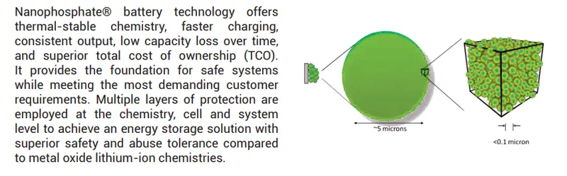
- The ANR26650M1-B cells use lithium iron phosphate (LiFePO4) chemistry, which is known for its safety, stability, and long cycle life. LiFePO4 batteries are less prone to thermal runaway and do not release oxygen during operation, which reduces the risk of fire and explosion.
- The ANR26650M1-B cells are relatively large and heavy compared to some other types of lithium-ion cells, which can make them less suitable for applications where weight and space are critical factors.
- The ANR26650M1-B cells have a cylindrical shape with a diameter of 26 mm and a length of 65 mm.
- The ANR26650M1-B cells have a nominal energy density of around 100-120 Wh/kg, which is lower than the energy density of some other types of lithium-ion cells such as those based on lithium cobalt oxide (LiCoO2) or lithium nickel cobalt aluminum oxide (NCA). However, the lower energy density is offset by the safety, stability, and long cycle life of the LiFePO4 chemistry.
- The ANR26650M1-B cells have a relatively low self-discharge rate, which means they can maintain their charge for longer periods of time when not in use.
Conclusion:
- These are the process or things to take in consideration while mechanical design of battery pack