Mechanical design of battery pack
Aim
To create a mechanical design of battery pack
Objectives
Prepare a detailed battery pack drawing along with its enclosure. Battery pack capacity: 18 kWh Cell: ANR26650M1-B
Introduction
Battery Cells come in fixed voltages and capacities. Capacities do vary, but voltages don’t. In order to meet our power requirements a battery pack may need to be used. The type of battery, the number of cells, the shape of the pack, and the components of the pack will be determined by the voltage and load current of the device being powered. Other considerations will be available space, operating temperature, usage conditions, transportation requirements, and charge/discharge specifications.
Explanation
Given, Battery pack capacity: 18 kWh Cell: ANR26650M1-B
Assumption, Battery pack voltage: 330V
Properties of Selected cell
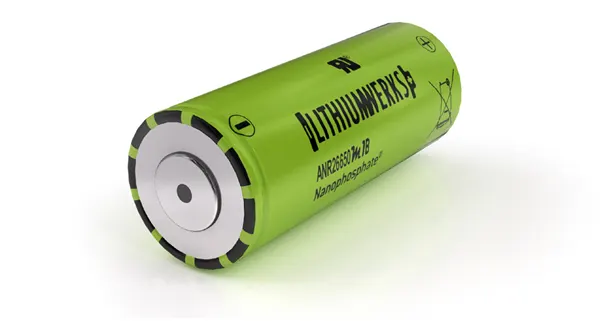
Lithium Werks’ 26650 cells are capable of delivering very high power due to its use of patented Nano phosphate battery technology. Based on lithium iron phosphate chemistry (LiFePO4), the cells are inherently safe over a wide range of temperatures and conditions. Whether the application requires outstanding cycle life or stable float reliability, the Lithium Werks’ 26650 cells are suitable for a wide variety of power, pulse, or stand-by applications.
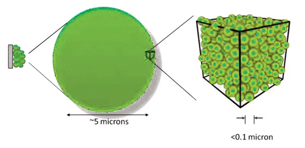
Nano phosphate battery technology offers stable chemistry, faster charging, consistent output, excellent cycle life and superior cost performance. It provides the foundation for safe systems while meeting the most demanding customer requirements. Multiple layers of protection are employed at the chemistry, cell and system level to achieve an energy storage solution with superior safety and abuse tolerance compared to metal oxide lithium-ion chemistries.
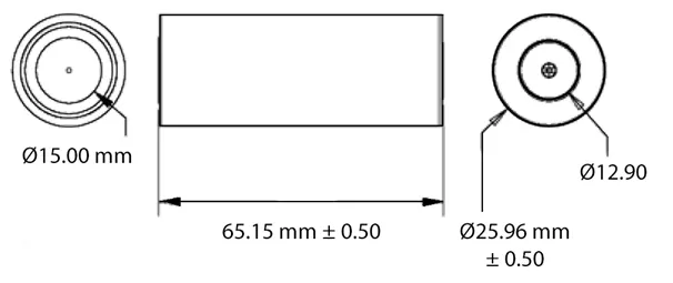
Specs for ANR26650M1B
|
Nominal Voltage |
3.3 V |
|
Nominal Capacity @ 23 ºC Typ (Min) |
2.6 Ah (2.5) |
|
Energy @ 23 ºC |
8.25 Wh |
|
Specific Power |
2600 W/kg |
|
Impedance (1KHz AC) Typ |
6 mΩ |
|
Cycle Life at 1C/1C, 100% DOD |
> 4000 cycles |
|
Max Continuous Discharge Current |
50 A |
|
Max Pulse Discharge Current (10s) |
120 A |
|
Minimum Voltage / HPPC Pulse |
2 V / 1.6 V |
|
Temperature |
-30 ºC to 55 ºC |
|
Recommended Charge Current |
3 A |
|
Max Continuous Charge Current |
10 A |
|
Max Pulse Charge Current (10s) |
20 A |
|
Float Voltage |
3.45 V |
|
Recommended charge V |
3.6 V, taper to 125mA |
|
Temperature Range |
0 ºC to 55 ºC |
|
Storage Temperature |
-40 ºC to 60 ºC |
|
Diameter |
Ø25.96 +/- 0.5 mm |
|
Length |
65.15 +/- 0.5 mm |
|
Mass |
76 g +/- 1.0 g |
Calculations
|
Parameter |
Equation |
Calculation |
Value |
|
Number of cells |
Pack Capacity/ (Nominal voltage * Cell capacity) |
18000 / (3.3 * 2.5) |
2182 |
|
No. Of cells in series |
Pack Voltage / Nominal Voltage |
330 / 3.3 |
100 |
|
No. Of cells in parallel |
No. Of cells / No. Of cells in series |
2182 / 100 |
22 |
|
Total Capacity pack |
Nominal cell capacity * No. Of cells in parallel |
2.5 * 22 |
55 Ah |
|
Total Energy of pack |
Pack voltage * Pack capacity |
330 * 55 |
18.15Kwh |
So the battery pack is having 18 Kwh capacity with 100S22P configuration.
Mechanical Designing
From calculation we concluded the number of cells in battery pack as 2182. In that pack, 100 cells are in series connection and 22 cells are in parallel connection.
The total dimensions of the battery pack can be calculated as follows. Diameter of one cell is 26mm and length is 65mm. Weight of one cell is 76g.
Total weight of pack will be around 170kg. (76 * 2182 + Accessories)
Height of the cell will depend up on our arrangement of batteries. For one row of cell we can calculate the height as 100mm including other accessories.
Length and breadth will also depend up on number of cell arranging in holder. Length or breadth can be calculated as diameter of one cell * number of cells + accessories. If we arrange is linearly, then length will be about 3000mm and breadth will be 650mm.
Assembly Procedure
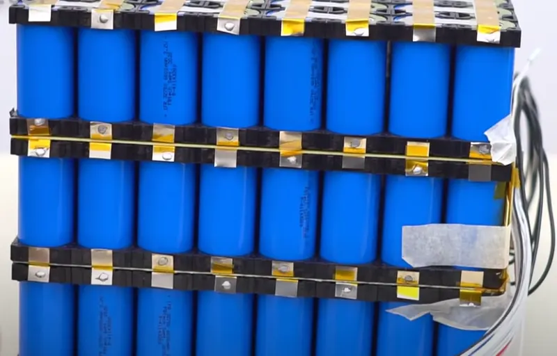
Base for battery pack is made using battery holders. It will align all the cells in required shape. Battery holder will also provide enough spaces between cells to avoid unwanted properties like vibrations.
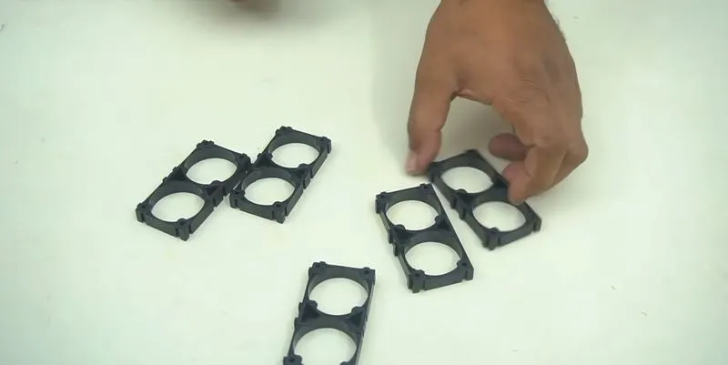

We can connect each holder up to our specifications
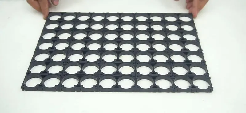
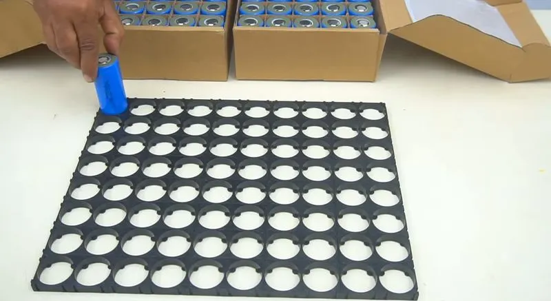
Now place each cells in the holder
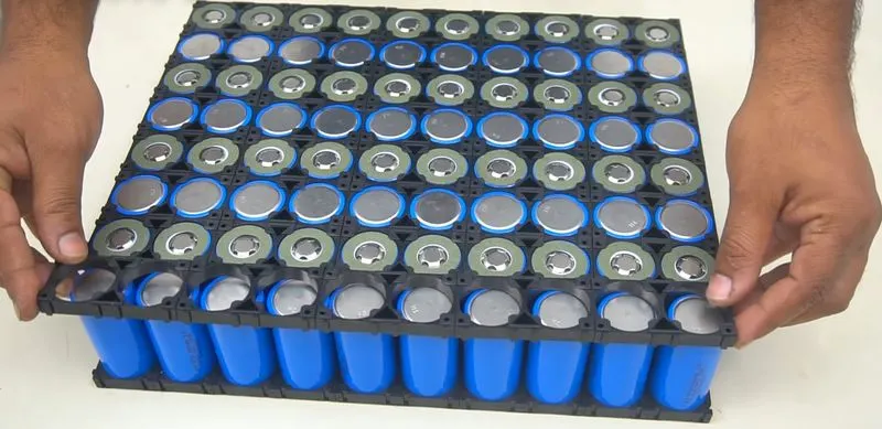
Place battery holder on top of the pack to make it rigid enough for the use
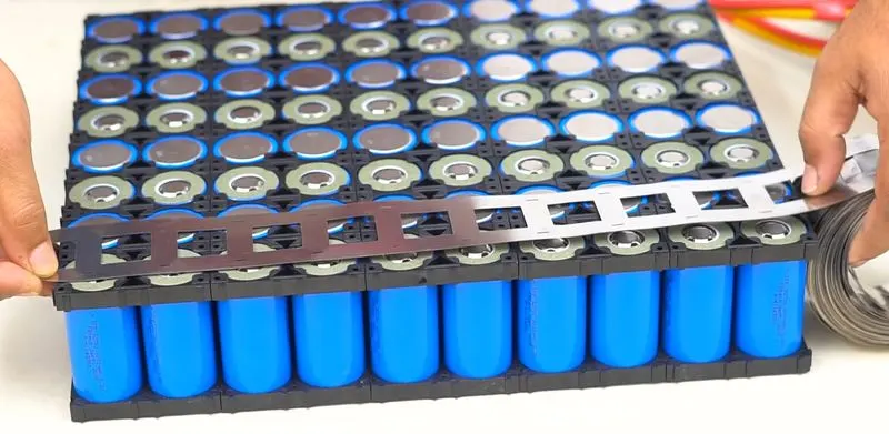
Now we can connect the cells with nickel strips
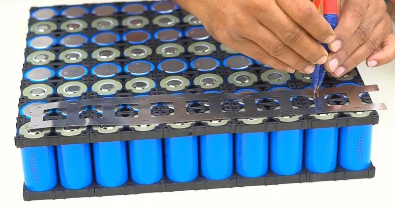
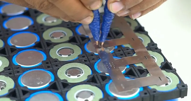
Spot welding is used to connect the cells with the pure nickel edge strips.
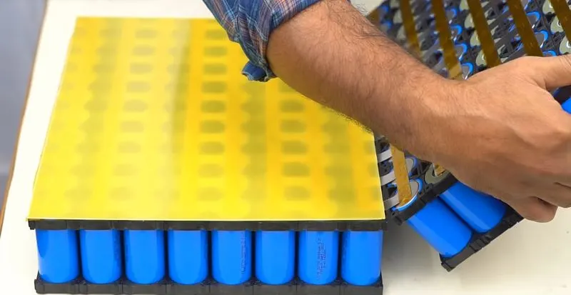
PVC heat sink films can be used to connect multiple packs of batteries.
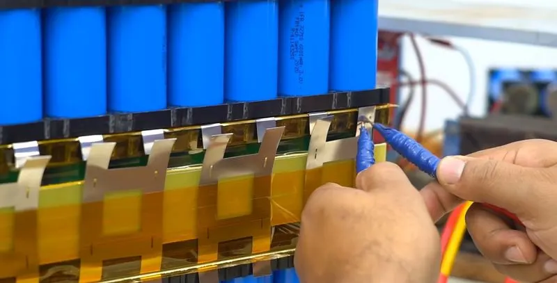
Multiple pack is again connected with nickel strips
Conclusion
Mechanical design of battery pack was done
Reference
Images Credit : Lithium Werks & Creative etc