Project 1 Mechanical design of battery pack
AIM
To prepare a detailed battery pack drawing along with its enclosure and to state assumptions.
OBJECTIVES
Battery pack design using A123 ANR26650M1-B type Li-ion cells and with battery pack capacity 18 kWh.
THEORY
A battery pack is made up of any number cells which are arranged in series or/and parallel as per the requirement.When a number of cells are put into a frame to protect them better from external shocks such as heat or vibration, this is called a module. And when a number of modules come together with a BMS (Battery Management System) and a cooling device that control and manage battery’s temperature, voltage, etc., this is called a pack. A battery pack construction includes placing the battery using a holder , electrical connections and mechanical housing & arrangements.
Cells are first arranged inside a module and then multiple number of this modules are then connected to make the battery pack.
A battery pack contains multiple sensors and will also have battery balancing circuit which balances the battery pack.
A properly designed battery pack should take care of issues related to thermal stability , vibration isolation and impact resistance. Also it should minimize thermal and mechanical interactions between different units of the battery pack at each level.
Another important thing to consider while designing a battery pack is cell spacing , researches shows that increasing cell to cell spacing for a battery pack from 1mm to 10mm can lead to a loss of approximately `1^circC` in the steady state cell core temperature.
It is also recommended to use one pressure release valve , which is designed to set off at a pre-specified pressure. This minimizes the safety risk posed in the event of battery failure. Along with that one or more gas exhaust nozzles are incorporated. These will open during thermal runaway events.
To prevent thermal runaway to larger parts of the battery pack , a thermal barrier is used. This will prevent melting of mounting brackets or other parts related to mechanical enclosure in case of increased temperature caused by thermal runaways.
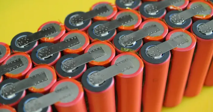
For small cylindrical cells , preferred casing material is metal and connections welded nickel or copper strips or plates.
Another thing to consider while designing a battery is crash protection. A battery pack has to protected by rigid structures so as to avoid damaging the cells in case of any crash happens.
Also vibration isolation has to be addressed while designing a battery pack. When a vehicle is driven it will produces vertical low frequency vibrations , these vibrations can lead to dynamic mechanical load being developed on the electrical part of the battery pack. Such loads can lead to loss of electrical continuity and fatigue failure of the casing.
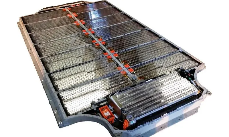
A battery pack used in Tesla cars is shown below,
DESIGNING BATTERY PACK
The battery pack is made using A123 ANR26650M1-B type Li-ion cells and have to output 18kWh power.
Technical data sheet for this cell is shown below,
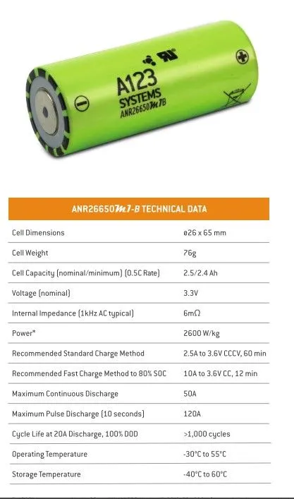
Here we can see that the diameter of this cell is 26mm and height is 65 mm.
Cell arrangement calculation
To get 18kWh output we can use many variations of cell arrangement. Here we are assuming the battery pack to be of 300V and 60Ah capacity.
Now let us calculate how much cells are to be put in series so as to get 300V output.
For this we know nominal voltage of the cell is 3.3V ,
`"Total cells in series" = 300/3.3`
`= 90.9 approx 91`
So 91 cells in series connection is required to get an output voltage level of 300V.
Now let us look how many in parallel is required to get 60Ah capacity,
For this we know the minimum cell capacity is 2.4Ah,
`"Total cells in parallel" = 60/2.4`
`= 25`
So 25 cells in parallel connection is required to get a total capacity of 60Ah.
So the cell arrangement is 91S25P, by using this combination we will get a power output of 18kWh.
`"Total number of cells " = 91*25`
`=2275 cells`
Battery pack enclosure dimension calculation
Now let us design the enclosure. For this design let us keep the design simple. Let the enclosure be box type with top side open. The base plate be of thickness 5mm and the four side walls be of thickness 2mm.
Let the spacing between cells be 2mm.
So total length of the enclosure is the length for placing 91 cells in series.
As we know the diameter is 26mm and spacing is 2mm , the total length will be ,
`= ((26+2)*91 ) + 2`
`=2550 mm`
And the total width of the enclosure is calculated as follows,
Here we have 25 parallel modules of cells , so width is,
`= ((26+2)*25) + 2`
`= 702 mm`
And the height of the enclosure is height cell with some clearance. So in this case the height is 65mm and let the clearance be 5mm , so the total height of the enclosure will be including the thickness of the base plate.
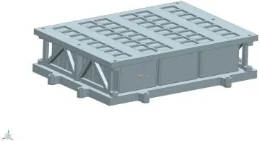
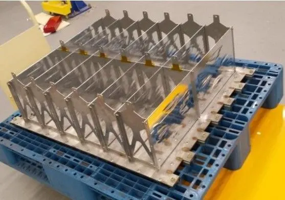
This enclosure after manufacturing will look like,
Weight of battery pack estimation
The weight of enclosure can be assumed to be 50Kg , the material used is Al 6061 which has a density of `2700(Kg)/m^3`.
Now to calculate the total cell weight , weight of one cell is 76g.
`"Total number of cells" = 91*25`
`= 2275 cells`
`"Weight of 2275 number of cells" = (2275 * 76)/1000`
`=172.9 Kg`
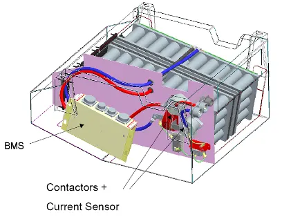
Let us assume the weight of other parts of the battery pack to be roughly around 10Kg. This 10 Kg includes BMS,contactors,current sensor,connectors and all other small parts of the battery pack.
Now the `"total weight of the battery pack" = 50 + 173 + 10 = 233Kg`
Steps involved in assembly of battery pack
First of all the cell are hold in its position using holders. They hold the cells as shown below,
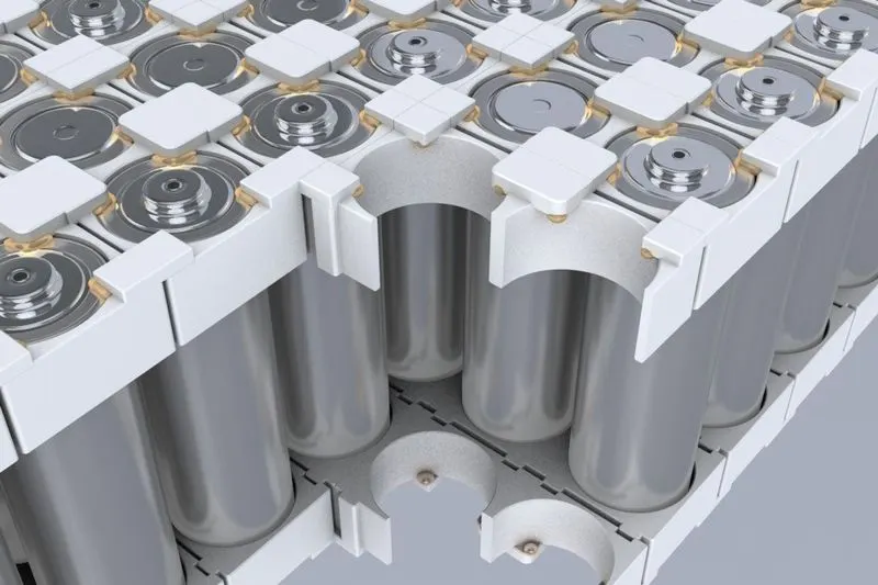
After placing inside the holder , the connections are made. Here we have used metal strips which are spot welded to connect between cells as shown below,
After proper connections and wiring is done , we will place this inside the enclosure.
The battery after wiring is shown below,
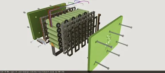
This is put inside the enclosure as shown below,
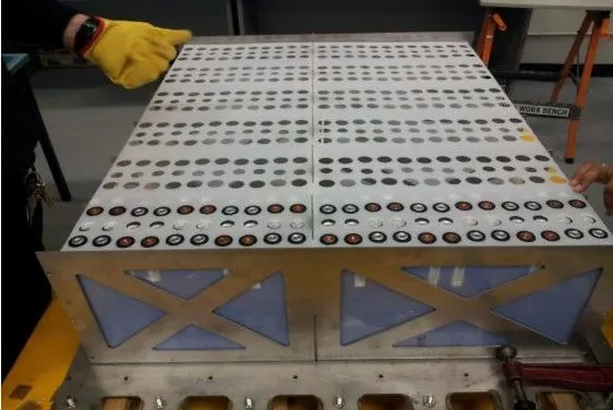
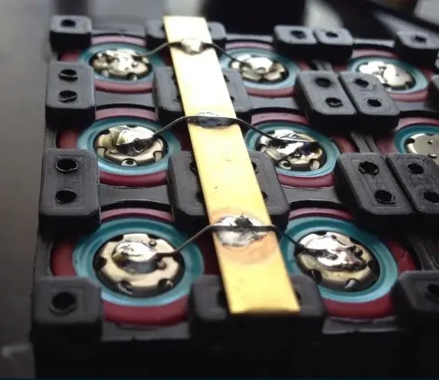
For cell level protection , fuses are placed on top of each cell as shown below ,
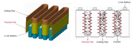
Also for thermal management we will provide ducts inside the enclosure so as to pass fluids. This is done as shown below,
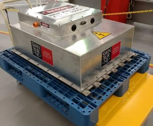
After placing inside the enclosure , this enclosure is then covered with a outer casing house. In this outer casing the top cover can be opened through which we can access the electrical accessories like battery controller and BMS. This final finished battery pack is shown below,
The BMS and other electrical parts on top of this casing is shown below,
CONCLUSION
The battery pack has been designed using the A123 ANR26650M1-B type Li-ion cells that will output 18kWh of power successfully.