Project 1 Mechanical design of battery pack
Project 1 :- Mechanical design of battery pack.
QUESTION:
Battery pack capacity: 18 kWh
Cell: ANR26650M1-B
Prepare a detailed battery pack drawing along with its enclosure. State your assumptions.
ANSWER:
Details of Cell: ANR26650M1-B:
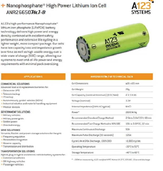
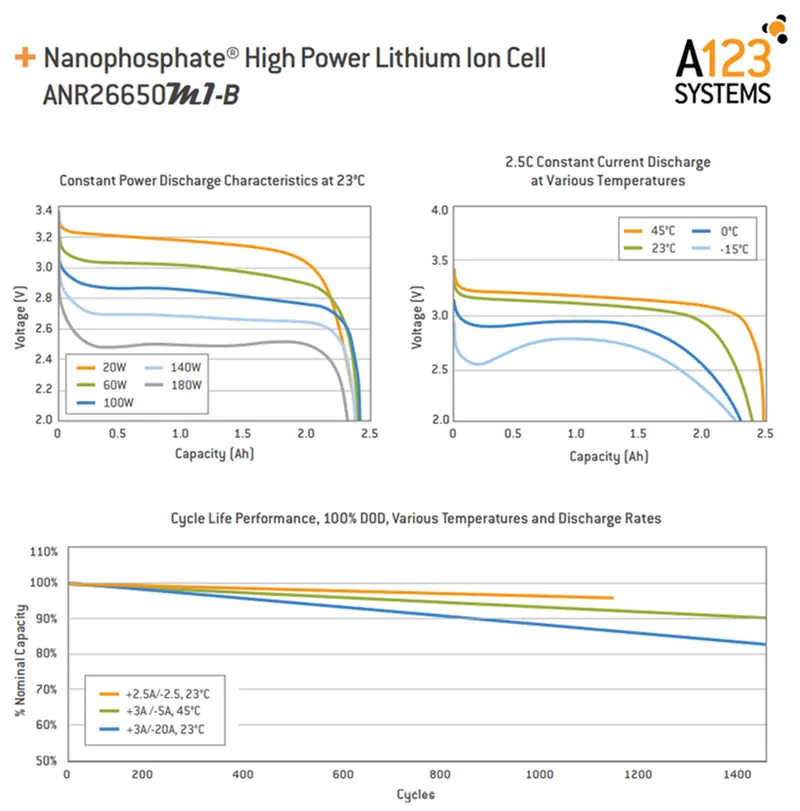
ANR26650M1-B specification:
Nominal Rating:
- voltage :3.3 volts
- capacity:2.5Ah
- energy: 8.25Wh
- specific power: 2600W/kg
- impedence(1KHz AC typical) 6 mΩ
- cell type: 26650 lithium ion power cylindrical cell.
Discharging:
- max.continuous discharage: 50A
- max pulse discharge current > 50% SOC (10sec): 120A
- minumum voltage:2 volts
- temperature: -30 to 55 degree celcious
charging:
- recommended std.charge: 2.5A
- max charge rate:10A
- max pulse charge current<50% SOC (10sec) :25A
- float voltage: 3.45 volts
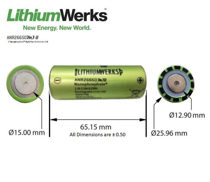
mechanical parameters:
- diameter: 25.96 +/- 0.5 mm
- length: 65.15+/- 0.5 mm
- mass : 76g
calculation as per assumptions: 18 KWh battery pack.
- calculation for designing an 18 KWh battery pack basically 18 KWh is energy require to achive the vehicle it proper range and its depend on the voltage(V) and amp-hr capacity(Ah)
1] single cell energy(Wh) = [the value of a single cell energy is used to calculate the total energy of the battery pack]:
single cell energy(Wh)= cell capacity(Ah)* cell voltage(V)
= 2.5Ah *3.3V
= 8.25 Wh
2] single cell volume calculation:
single cell volume = pi(r^2)*h
= 3.14(0.013^2)*0.065
= 0.03451 m^3
3] single cell energy density:
A] volumetric energy(Wh/m^3) = single cell energy / volume of each cell
= 8.25Wh / 0.03451 m^3
= 239.0611 Wh/m^3
B] gravimetric energy(Wh/kg) = single cell energy / single cell mass
= 8.25Wh / 0.076 kg
=108.5526 Wh/Kg
calculation of high voltage battery pack
for design and calculation of battery pack here,i assume a vehicle to achive 200km in 18 KWh battery pack also i assume 145.2 nominal voltage for series connection.
so we assume that,
vehicle range = 200 Km
battery pack capacity = 18.1210KWh
now,
4] we will calculate per Km average energy requirement = 18120.96 (Wh)/200 (Km)
= 90.60 Wh/Km
therefor,
battery pack total energy = average energy * km
= 90.60Wh * 200km
= 18120.96 Wh
let's assume nominal voltage for seres connection= 145.2 V basically this depends upon the motor power,we can decide the value according to the motor.
5] number of cell connected in series = nominal voltage of seres connection/nominal voltage of a single cell
= 145.2V/ 3.3V
= 44 cell
44 cell will be connected in a series connection to provide a proper voltage.
6] energy for battery pack(Wh) = number of cell connected in series * single cell energy
= 44* 8.25Wh
= 363 Wh
7]number of cell connected in parallel = battery pack total energy(Wh)/energy for battery pack(Wh)
= 18120.96 Wh/363 Wh
= 50 cell
50 cell will be connected in a parallel to provide a proper capacity power.
8] battery pack total energy(Wh) = no. of cell connected in parallel * energy for battery pack
= 50* 363 Wh
= 18.150 KWh
9] battery pack capacity(Ah) = no. of cell connected in parallel * single cell capacity(Ah)
= 50*2.5 Ah
= 125 Ah
the value of battery pack capacity is used for the total power required by the vehicle.
10] total number of cell for battery pack = no. of cell connected in parallel * number of cell connected in series
= 50*44
=2200 cells
2200 cells will be used to make a complete battery pack.
11] mass of battery pack = total number of cell for battery pack * mass of single cell
= 2200 * 0.076 kg
= 167.2 kg
167.2 kg its the total weight of cell connected in parallel and series
12] total volume of the battery pack = total number of cell for battery pack * volume of single cell
= 2200 * 0.0345 m^3
= 75.9 m^3
75.9 m^3 its the volume occupied by total cell used in battey pack.
13] cell peak current(A) = C rate(max pulse charge current)* single cell capacity
= 20* 2.5
= 50A
14] battery pack peak current(A) = cell peak current(A) * no. of cell connected in parallel
=50*50
= 2500A
15] battery pack peak power(W) = battery pack peak current(A) * voltage of series connection
= 2500 A * 145.2
= 363 KW
16] cell continuous current(A) = C rate(max continuous charge current)* single cell capacity
= 10* 2.5
= 25A
17] battery pack continuous current(A) = cell continuous current(A) * no. of cell connected in parallel
= 25*50
= 1250 A
18] battery pack continuous power(W) = battery pack continuous current(A) * voltage of series connection
= 1250 A * 145.2
= 181.5 KW
Details of Cell: ANR26650M1-B:
cell connected in series and parallel:
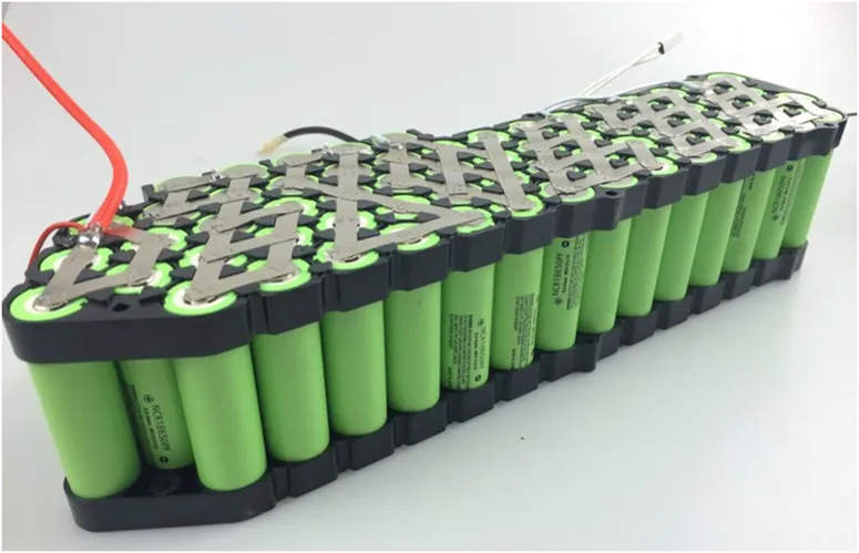
In almost any device that uses batteries, you do not use just one cell at a time. You normally group them together serially to form higher voltages, or in parallel to form higher currents. In a serial arrangement, the voltages add up. In a parallel arrangement, the currents add up. The following diagram shows these two arrangements:
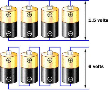
The upper arrangement is called a parallel arrangement. If you assume that each cell produces 1.5 volts, then four batteries in parallel will also produce 1.5 volts, but the current supplied will be four times that of a single cell. The lower arrangement is called a serial arrangement. The four voltages add together to produce 6 volts.
Battery holder:
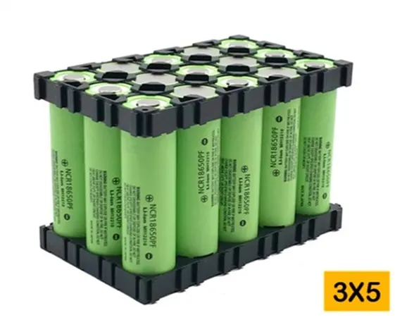
A battery holder is one or more compartments or chambers for holding a battery. For dry cells, the holder must also make electrical contact with the battery terminals. For wet cells, cables are often connected to the battery terminals, as is found in automobiles or emergency lighting equipment.
A battery holder is either a plastic case with the shape of the housing moulded as a compartment or compartments that accepts a battery or batteries, or a separate plastic holder that is mounted with screws, eyelets, glue, double-sided tape, or other means. Battery holders may have a lid to retain and protect the batteries or may be sealed to prevent damage to circuitry and components from battery leakage. Coiled spring wire or flat tabs that press against the battery terminals are the two most common methods of making the electrical connection inside a holder. External connections on battery holders are usually made by contacts with pins, surface mount feet, solder lugs, or wire leads.

Electric connection:

Battery pack with BMS[battery management system]:
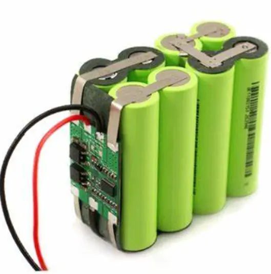
The Battery Management System (BMS) is connected to the cells modules and battery which is used to identify the critical situations like the voltage, temperature, battery capacity values at the running of the battery time. It is mainly used for the monitoring purpose and balancing of the cells in the battery pack. By this we can operate with out and damages which leads to explode at critical situations. The outlook of the BMS with the cells look like as shown.
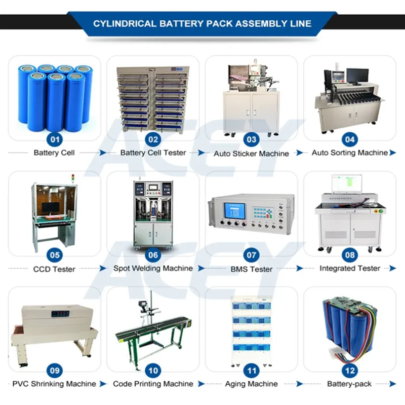
shrinking machine is used to shrink the battery pack with certain heated temperature in the form of air in the closed loop. The code printing and the aging machine are used to print he code value of the battery cell like ANR26650M1-B and life time of the battery be calculated respectively.
The testers are used to confirm the cell total parameters like voltage, capacity, temperature, pressure, BMS, chemicals etc.

Venting for EV Battery Packs
Batteries for electric vehicles (EVs) need protection from harsh external conditions. Generally located on the underside of the vehicle, EV battery enclosures protect the cells from exposure to water, dust, debris, and other elements. Like other enclosures, EV battery enclosures also undergo temperature and pressure changes that can lead to problems without proper venting. But EV batteries present unique venting challenges including potentially dangerous thermal runaway conditions. Considering these challenges, integration of design, manufacturing, installation, and testing are crucial to optimal EV battery venting performance.
DUAL-STAGE VENTING MITIGATES THERMAL RUNAWAY
passive venting : pressure equalization , gradual pressure change
active venting : handle rapid pressure buildup in a thermal runway event , prevent enclosure rupture