Project 1 Mechanical design of battery pack
Title : Prepare a detailed battery pack drawing of cell ANR 26650M1-B along with its enclosure with assumptions.
Introduction:-
- An electric battery is defined as a device that makes use of either one or an assembly of electrochemical cells that convert the stored chemical energy within them into electrical energy.
- Each cell has a positive terminal, cathode, and a negative terminal, anode.
- The individual cells are connected in various combinations of series and parallel connection to get a battery of desirable characteristics.
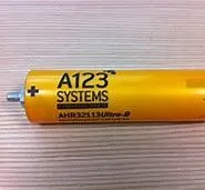
- A123’s high-performance Nanophosphate lithium iron phosphate (LiFePO4) battery technology delivers high power and energy density combined with excellent safety performance and extensive life cycling in a lighter weight, more compact package. Our cells have low capacity loss and impedance growth over time as well as high usable energy over a wide state of charge (SOC) range, allowing our systems to meet end-of-life power and energy requirements with minimal pack oversizing.
Applications:
Commercial Solutions:
Advanced lead acid replacement batteries for:
- Datacenter UPS
- Telecom backup
- IT backup
- Autonomously guided vehicle (AGV's)
- Industrial robotics and material handling equipment
- Medical devices
Government Solutions:
- Military vehicles
- Military power grids
- Soldier power
- Directed energy
Grid Solutions:
- Frequency regulation
- Renewables integration
- Reserve capacity
- Transmission and Distribution
Transportaion Solutions:
- Commercial vehicles
- Off-highway vehicles
- Passenger vehicles
ANR26650M1-B Technical data:
|
Cell Dimensions
|
26 x 65 mm
|
|
Cell Weight
|
76 g |
|
Cell Capacity (nominal/minimum) (0.5C Rate)
|
2.5/2.4 Ah
|
|
Voltage (nominal)
|
3.3 V |
|
Internal Impedance (1kHz AC typical)
|
6mΩ
|
| Power |
2600 W/kg
|
|
Recommended Standard Charge Method
|
2.5A to 3.6V CCCV, 60 min
|
|
Recommended Fast Charge Method to 80% SOC
|
10A to 3.6V CC, 12 min
|
|
Maximum Continuous Discharge
|
50 A |
|
Maximum Pulse Discharge (10 seconds)
|
120 A |
|
Cycle Life at 20A Discharge, 100% DOD
|
>1,000 cycles
|
|
Operating Temperature
|
-30°C to 55°C
|
| Storage Temperature |
-40°C to 60°C
|
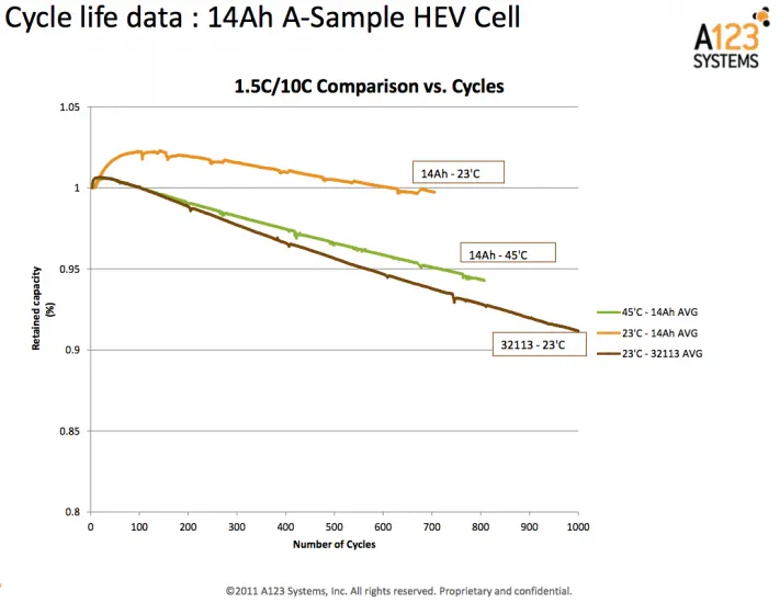
- High-performance Nanophosphate® lithium iron phosphate (LiFePO4) battery technology delivers high power and energy density combined with excellent safety performance and extensive life cycling in a lighter weight, more compact package.
- Cells have low-capacity loss and impedance growth over time as well as high usable energy over a wide state of charge (SOC) range, allowing systems to meet end-of-life power and energy requirements with minimal pack oversizing.
Calculations :
1. Volume of each cell, Vc [m3]
`V c = π ⋅ ( D c ) ^2 /4⋅ L c`
Lc - battery cell length [m]
Dc - battery cell diameter [m]
Vc = (π * 0.0262 /4)* 0.065 = 0.034510 m3
2. Battery cell energy, Ebc [Wh]
Ec=Cc⋅Uc
Cc - battery cell capacity [Ah]
Uc - battery cell voltage [v]
Ec = 2.5*3.3 = 8.25 Wh
3. Battery cell energy density
Volumetric energy density, uV [Wh/m3]
uV=Ec/Vc
uV = 8.25/0.034510 = 108.55 Wh/m3
Gravimetric energy density, uG [Wh/kg]
uG=Ec/mc
mc - battery cell mass [kg]
uG = 8.25/0.076 = 239.06 Wh/kg
- With the above cell parameters and the core requirements for the battery (nominal voltage, average energy consumption and vehicle range), we calculate the main parameters of the high voltage battery.
High voltage battery
1. The Battery pack total energy Eb [Wh]
- The required battery pack total energy Eb [Wh] is calculated as the product between the average energy consumption Eavg [Wh/km] and vehicle range Dv [km].
- Here we’ll design the high voltage battery pack of 18Kwh for a vehicle range of 250 km.
Therefore,
Eb = 18Kwh Dv = 200km
Eavg = Eb / Dv = 18000/200 =90Wh/km
2. The Battery pack Voltage, Ub [V]
- The battery pack voltage is considered to be 300V high voltage.
Ub = 300V
we are going to consider that the battery pack is made up only from several strings connected in parallel.
3. The number of battery cells connected in series Ns
- Ns in a string is calculated by dividing the nominal battery pack voltage Ub [V] to the voltage of each battery cell Uc [V]. The number of strings must be an integer.
Ns=Ub/Uc
Ns = 300/3.3 = 90.90 = 91 S
4. The energy content of a string Es [Wh]
- Eb is equal with the product between the number of battery cells connected in series Ns [-] and the energy of a battery cell Ec [Wh].
Es=Ns⋅Ec
Es = 91 * 8.25 = 750.75 Wh
5. The number of battery cells connected in Parallel, Np
- The total number of strings of the battery pack Np [-] is calculated by dividing the battery pack total energy Eb [Wh] to the energy content of a string Es [Wh]. The number of strings must be an integer. Therefore, the result of the calculation is rounded to the higher integer.
Np=Eb/Es
NP = 18000/750.75 = 23.9 = 24 P
We can now recalculate the battery pack total energy Eb [Wh] as the product between number of strings Np [-] and the energy content of each string Es [Wh].
Eb = 24*750.75 = 18.02 KWh
6. The battery pack capacity Cb [Ah]
-
Cb is calculated as the product between the number of strings Np [-] and the capacity of the battery cell Cc [Ah].
Cb=Ns⋅Cc
Cb = 24*2.5 = 60Ah
7. The total number of cells of the battery pack Nb
- The total number of cells of the battery pack is calculated as the product between the number of strings Np [-] and the number of cells in a string Ns [-].
Nb=Np⋅Ns
Nb = 91*24 = 2184 no of cells
- The size and mass of the high voltage battery are very important parameter to consider when designing a battery electric vehicle (BEV).
- In this example we are going to calculate the volume of the battery pack considering only the battery cells. In reality there are other factors to consider, like: electronic circuits, cooling circuit, battery casing, wiring, etc.
8. The battery pack mass (cells only) mb [kg]
- The battery pack mass (cells only) is the product between the total number of cells Nb [-] and the mass of each battery cell mc [kg].
mb=Nb⋅mc
mb = 2184 * 0.076 = 165.98 kg
9. The volume of the battery pack (cells only) Vb [m3]
- The volume of the battery pack (cells only) is the product between the total number of cells Nb [-] and the mass of each battery cell Vc [m3].
- This volume is only used to estimate the final volume of the battery pack, since it does not take into account the auxiliary components/systems of the battery.
Vb=Nb⋅Vc
Vb = 2184 * 0.034510 = 75.37 m3
- The volume can be also calculated function of number of strings and number of cells in a string. This calculation method is more appropriate for cylindrical cell, since the volume occupied by a cylindrical cell must take into account the air gap between cells.
10. The string peak current Ispc [A]
- The string peak current is the product between the peak C-rate of the battery cell C-ratecp [h-1] and the battery cell capacity Cb [Ah].
Isp=Cratecp⋅Cb
Isp = 24*2.5 = 60A
11. The battery pack peak current Ibp [A]
- The battery pack peak current is the product between the string peak current Ispc [A] and the number of strings of the battery pack Np [-].
Ibp=Isp⋅Np
Ibp = 60 * 24 = 1440 A
12. The battery pack peak power Pbp [W]
- The battery pack peak power Pbp [W] is the product between battery pack peak current Ibp [A] and the battery pack voltage Ub [V]
Pbp=Ibp⋅Ub
Pbp = 1400 * 300 = 432 KW
13. The string continuous current Isc [A]
- The string continuous current is the product between the continuous C-rate of the battery cell C-ratebc [h-1] and the battery cell capacity Cb [Ah].
Isc=Cratebc⋅Cb
Isc = 10 * 2.5 = 25 A
14. The battery pack continuous current Ibc [A]
- The battery pack continuous current is the product between the string continuous current Isc [A] and the number of strings of the battery pack Np.
Ibp=Isc⋅Np
Ibc = 25 * 24 = 600A
15. The battery pack continuous power Pbc [W]
- The battery pack continuous power is the product between battery pack continuous current Ibc [A] and the battery pack voltage Ub [V].
Pbc=Ibc⋅Ub
Pbc = 600 * 300 = 180KW
The mass and volume are calculated only at cell level, taking into account the cell dimensions and mass. The battery pack which will be in the vehicle will have additional components (wires, electronic components, soldering, case, etc.), which will increase both the final volume and mass.
The results
| Manufacturer | A123-Systems |
| No of cells in string [-] | 91 |
| String energy [Wh] | 750.75 |
| No of strings [-] | 24 |
| BP energy [kWh] | 180.2 |
| BP capacity [Ah] | 60 |
| No total cells [-] | 2184 |
| BP mass [kg]* | 165.98 |
| BP volume [l]* | 75.37 |
| BP peak current [A] | 1440 |
| BP peak power [kW] | 432 |
| BP continuous current [A] | 900 |
| BP continuous power [kW] | 180 |
Assembly of the battery pack
Component of the battery pack
- 2200 cells
- Nickel strip
- PVC heat sink film
- spot welder
- Connected
- Cell holder
- Solder
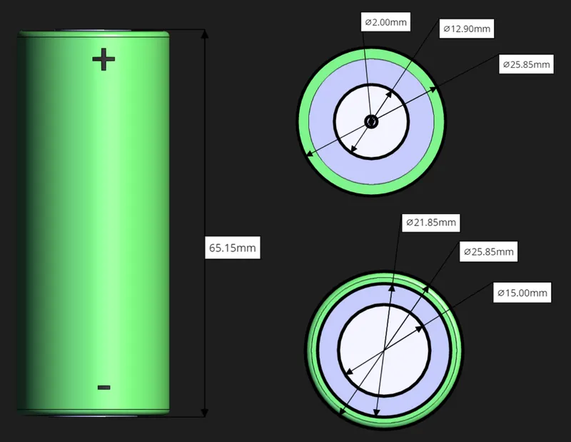
- A battery consists of one or more electrochemical cells (battery cells) which are converting chemical energy into electrical energy (during discharging) and electrical energy into chemical energy (during charging).
- The type of elements contained within a battery and the chemical reactions during discharging-charging events define the chemistry of a battery.A battery cell consists of five major components: electrodes – anode and cathode, separators, terminals, electrolyte and a case or enclosure
- Individual battery cells are grouped together into a single mechanical and electrical unit called a battery module.
- The modules are electrically connected to form a battery pack.
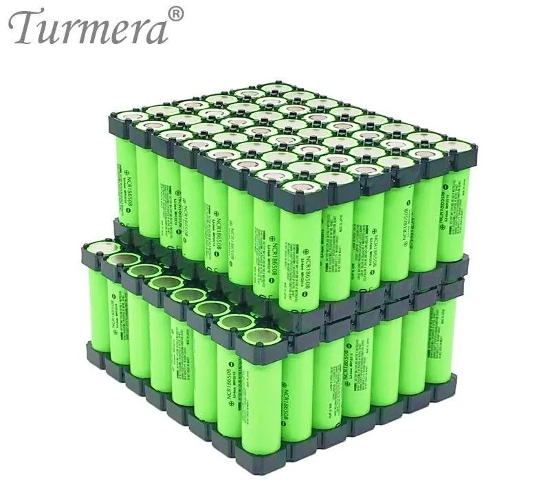
CELL HOLDER
- Each Cell holder can hold up to 4 battery cells, and can hold the battery pack with more holders connecting together, holder improves the stability of the battery back and reduces vibrations.
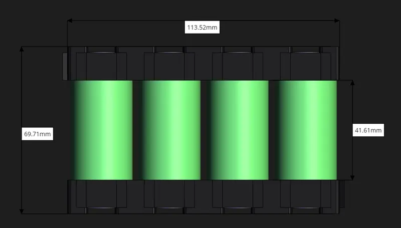
- Each of the cells are now need to be connected so that it could form a big battery module.
- So this holdes are very importatnt to provide the gapping between the battery and holding the battries in the correct manner.
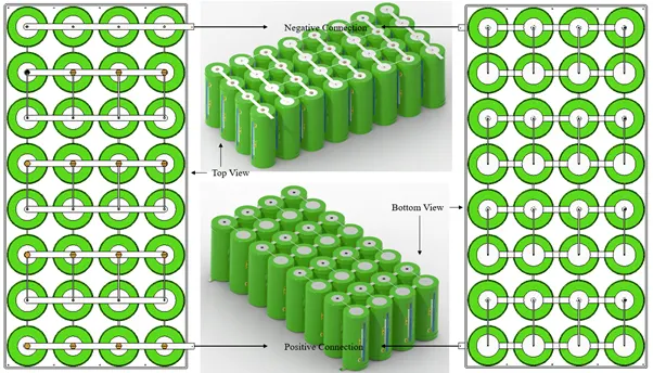
2) Connecting the cells:
- Now we will be connecting the cells with nickel strips using the spot welding process.
- The series connection will be made by connecting the positive terminal of the cells to the negative terminal.
- The parallel connection will be made by connecting the same terminal.
- When the cells are plalced in the holders ,then the cells need to be connect in the proper manner in series or parallel to get the desired results.
- Ususally a nickle strip is used between the cells to make the conatct.
ELECTRIC CONNECTIONS:
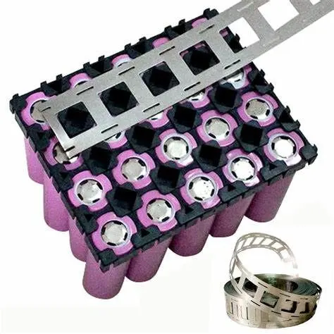
Nickel Strips/Tabs:
- Conductive metal strips are spot welded between all the cells of an electric bicycle battery pack. Nickel is the material of choice due to its low relative resistance and ease of spot welding.
- Pure nickel strip is ideal for use in the building of batteries. As the alloy has high corrosion resistance, can be efficiently spot welded and soldered and offers good conductivity with low electrical sensitivity, it allows battery sources to perform well, even in highly corrosive environments.
- Resistance spot welding, micro TIG welding, and laser welding processes all enable high quality volume production. The selection of one technology over another is usually made based on the application’s specific requirements and the alignment of the technology to these needs.

BMS:
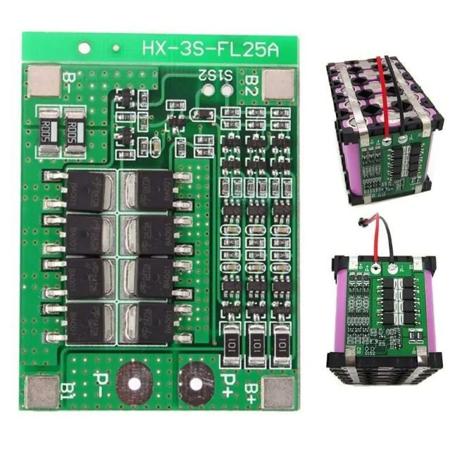
A battery management system (BMS) is an electronic system that manages a lithium battery pack and the main functionalities are
1. Monitors all of the parallel groups in the battery pack and disconnect it from the input power source when fully charged
2. Balance all the cells voltage equally
3. Doesn't allow the pack from over-discharged
BTMS (Battery Thermal Management System)
- For battery thermal modelling, a reliable thermal model of the battery is required. Starting from the heat generated from the battery, the thermal management system can be modelled by applying the correct boundary conditions. Battery thermal models are realized by considering the electrical/electrochemical characteristics and the thermal behaviour of the battery. Heat generation inside the batteries is governed by complex electrochemical reactions depending on temperature and state of the battery. Coupled, uncoupled or partially coupled models of the battery can be realized.
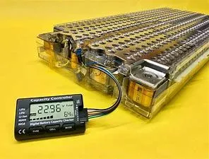
- There enough gap between the cells in our design to implement thermal strips or fins.

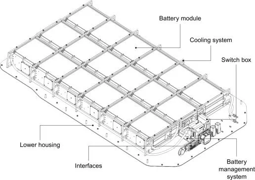
Design Benefits
• Up to 50 percent lighter than an equivalent steel design
• Best-in-class mass energy density at more than 160
watt-hours per kilogram, an extremely efficient design
for OEMs and Tier 1 battery pack manufacturers.
• Accommodates all battery cell types and is designed
particularly for battery electric vehicles with larger
power packs such as pick-up trucks, sport utility
vehicles and crossovers.
• Most cost-effective aluminum solution for mass
production electric vehicles when compared to
aluminum extrusion and casting-intense designs.
• Low price premium on $/kg saved compared
to equivalent steel designs at substantially
lower weight.
CONCLUSION
The design calculation for the battery pack was carried out and calculated and a table has been made for the same. The steps involved in the making of the battery pack have been listed out.
References :
https://www.hbmprenscia.com/products/vehicle-electrification/mechanical-durability
https://mpoweruk.com/pack_construction.htm