Project 1 Mechanical design of battery pack
Aim:
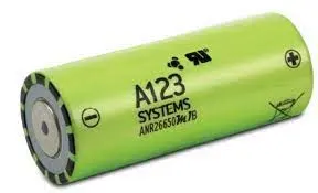
Prepare a detailed battery pack drawing along with its enclosure. State your assumptions and Battery pack capacity: 18 kWh Cell: ANR26650M1-B
Abstract:-
In this project, calculate the all parameters which are required for the build EV battery pack. use the Cell: ANR26650M1-B for our battery pack. In parameters, temperature, Depth of discharge, Operation current, Energy density, Work cycles, Battery capacity, State of Charge (SOC), State of Health (SOH), Ampere-hour (Ah) Capacity and calculate size, weight, volume, area, etc.
Methods:-
To build the Battery pack for any Electric Vehicle, have to calculate the first percentage of power then motor power. 18kWh battery Pack have to calculate how many cells are parallel and how many cells are in series. After calculation of series and parallel combination.
Battery pack architecture:
All high voltage battery packs are made up from battery cells arranged in strings and modules. A battery cell can be regarded as the smallest division of the voltage.Individual battery cells may be grouped in parallel and/or series as modules. Further, battery modules can be connected in parallel and/or series to create a battery pack. The total battery pack voltage is determined by the number of cells in series. For example, the total voltage of 6 cells connected in series will be the sum of their individual voltage.In order to increase the current capability the battery capacity, more strings have to be connected in parallel. For example, 3 strings connected in parallel will triple the capacity and current capability of the battery pack.
Battery Calculations:-

Battery Pack Calculation:-
Battery pack capacity: 18 kWh-Find the Voltage(V) and Capacity(AH)
Total Voltage(V) is 420V assumption value
Total Capacity(AH) = Total Energy/total Battery Voltage = 18000/420 = 43AH
Numbers of Series cell (NS) = Total voltage of battery pack/Individual cell voltage = 420/3.3 = 127NS
Numbers of Parallel cell (NP) = Total Capacity of battery pack/Individual cell Capacity = 42.85/2.5 = 17NP
Number of cells(N) = Numbers of Series cell (NS)*Numbers of Parallel cell (NP) = 127*17 = 2159N
Cell architecture = 127series and 17 parallel = 127S17P
Cell Weight = 76g
Number of cells = 2159
Battery pack Weight (W) = Cell Weight (W) * Number of cells + Weight of accessories = 76 * 2159 + 4.5 = 164Kg
Cell Technical Data
Cell Dimensions 26 x 65 mm
Cell Weight 76g
Cell Capacity (nominal/minimum) (0.5C Rate) 2.5/2.4 Ah
Voltage (nominal) 3.3V
Internal Impedance (1kHz AC typical) 6mΩ
Power* 2600 W/kg
Recommended Standard Charge Method 2.5A to 3.6V CCCV, 60 min
Recommended Fast Charge Method to 80% SOC 10A to 3.6V CC, 12 min
Maximum Continuous Discharge 50A
Maximum Pulse Discharge (10 seconds) 120A
Cycle Life at 20A Discharge, 100% DOD >1,000cycles
Operating Temperature -30°C to 55°C
Storage Temperature -40°C to 60°C
Discharging
Max Continuous Discharage: 50 A
Max Pulse Discharge Current >50% SOC (10s): 120 A
Minimum Voltage: 2 Volts
Temperature: -30ºC to 55ºC
Charging
Recommended Standard Charge: 2.5 Amps
Max Charge Rate: 10 Amps
Max Pulse Charge Current <50% SOC (10s): 25 A
Float Voltage: 3.45 Volts
Recommended charge V & Cut-off Current: 3.6 Volts, taper to 125mA
Temperature
(reduce charging current to 250mA when under 0ºC): 0ºC to 55ºC
Cell Calculations:-
1) Volume of the cell:
From Datasheet of Cell, we have 'r' and 'h' values r=0.013m and h=0.065m
Volume of the cell: pie*r^2*h = 3.14*0.013^2*0.065 =0.0000344929m^3
The volume of the cell is 0.0000344929m^3
2)Cell Energy Calculation:-
Cell Energy= Cell Capacity (Ah) × Cell Voltage (V) = 2.5 * 3.3= 8.25 Wh
Cell Energy is 8.25 Wh
Single Cell Energy Density:-
Volumetric energy (Wh/m^3) = Single Cell Energy / Volume of each cell
= 8.25 Wh / 0.0000344929m^3 =2,39,179.6572 Wh/m^3
Cell Formats:-
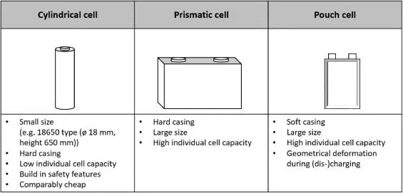
There are three basic types of battery cells used in electric vehicles: cylindrical cells, prismatic cells, and pouch cells. There are also coin cells, which are used in research and development for testing purposes, but never actually used in electric vehicles. On average, EVs with cylindrical cells have between 5,000 and 9,000 cells. This is in stark contrast with pouch cells, which only have a few hundred cells, and an even lower number in prismatic cells.
Cylindrical Cells
A Cylindrical cells are the least expensive format to manufacture because they are already self-contained in a casing that offers good mechanical resistance. The technology is not only cost-efficient, but it is also mature, making it a format easy to manufacture.
Because of their shape, cylindrical cells have limitations in terms of power. Cylindrical cells need to be manufactured in a smaller format than other types of cells to make sure they dissipate heat well, helping prolong the battery life.
Prismatic Cells
A prismatic cells can be 20 to 100 times larger than cylindrical cells. They can typically deliver more power and store more energy for the same volume because less material is used for the casing. The casing’s shape and thickness also allow better heat management than cylindrical cells.
Prismatic cells are popular among Chinese manufacturers because their preferred cell chemistry (the lithium iron phosphate battery) currently mostly exists in the prismatic format. Lately, prismatic cells have been gaining in popularity elsewhere in the world. While cylindrical cells used to be the most popular format, prismatic cells might take over a large share of the market in the upcoming years.
Pouch Cells
A Pouch cells are made to deliver more power than other cell types. They are also very efficient when it comes to space usage. Their soft plastic casing, however, means they have the lowest mechanical resistance of all cell types. For this reason, an additional structure needs to be added during pouch cell assembly to protect them from mechanical damage.
Welding
welding strips and tabs onto batteries in order to make battery interconnects and larger battery pack assemblies is a common production technique. Typically, battery interconnects are made from nickel strips, ideally designed with bifurcations and projections which are then resistance welded using parallel gap or step welding methods. For best and repeatable results, such methods rely on the quality of the weld heads, electrodes and power source.

With a constant drive to increase power handling and reduce losses, high-end battery pack manufacturers are looking for methods to attach more conductive interconnects, such as aluminium and copper, while additionally trying to reduce costs through simplifying the interconnect design. Such requirements often negate the possibility of using resistance welding methods because the interconnect is simply too conductive.
Laser Welding
Laser welding is a high-speed process that uses a highly focused beam of light to join surfaces. The laser beam is directed and moved using ultrafast moving X-Y mirrors. This provides a lot of flexibility, making it possible to weld any joint geometry as well as custom weld patterns. Pulsed fiber lasers are the lasers of choice for battery welding because they lead to smaller heat affected zones, lower porosity, and less spatter. They can weld thin or thick tabs, and process copper, aluminum, steel, and nickel as well as dissimilar materials.

Resistance Welding
Resistance welding, also called spot welding, is a method that uses copper or tungsten electrodes charged with electrical current to perform the welding. As pressure is applied on the area to be welded, an electrical current is passed through the electrodes. This generates heat at the contact area and bonds the two metals together.

Resistance welding can be used for foil-to-tab and tab-to-busbar welds. It is a cost-effective welding process that is ideal for DIY battery enthusiasts, but it can be automated as well.
Battery Management System
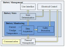
A Battery Management System (BMS), which manages the electronics of a rechargeable battery, whether a cell or a battery pack, thus becomes a crucial factor in ensuring electric vehicle safety. It safeguards both the user and the battery by ensuring that the cell operates within its safe operating parameters. BMS monitors the State Of Health (SOH) of the battery, collects data, controls environmental factors that affect the cell, and balances them to ensure the same voltage across cells.
Functions of the BMS
Fitting an EV with a BMS can improve safety. The battery management system performs the following four functions:
Monitoring battery parameters
This is the primary function of a BMS. It monitors the state of a cell as represented by parameters such as:
Voltage—indicates a cell’s total voltage, the battery’s combined voltage, maximum and minimum cell voltages, and so on.
Temperature—displays the average cell temperature, coolant intake and output temperatures, and the overall battery temperature.
The state of charge of the cell to show the battery’s charge level.
The cell’s state of health—shows the remaining battery capacity as a percentage of the original capacity.
The cell’s state of power——shows the amount of power available for a certain duration given the current usage, temperature, and other factors.
The cell’s state of safety——determined by keeping a collective eye on all the parameters and determining if using the cell poses any danger.
The flow of coolant and its speed.
The flow of current into and out of the cell.