Project 1 Mechanical design of battery pack
Abstract
This project is about mechanical design of Lithium-ion battery pack consisting of 18KWh. The cell name used in preparation is ANR26650M1-B, necessary assumptions were considered during building the cell then a module and finally a battery pack was developed. The battery model in MATLAB is configured, simulation run carried out in Simulink and results analysed. The results obtained matches the manufacturer specifications provided in the A123 Systems product datasheet.
Introduction
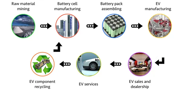
The flow diagram above summarise Lithium-ion battery development from extracting Lithium-ion from mine as raw material and right through to end of life during recycling phase. Lithium ion battery (LIB) manufacturing was established in the 1990s by Sony; however, advancements in the processes and the scientific understanding of those processes upon the final cell performances are still being understood. Lithium-ion (Li-ion) batteries have become the predominant energy storage means for off-grid solar products due to their high efficiency, low cost, high capacity, lack of memory effect, and long cycle life.
Cell Production
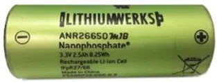
Lithium-ion cylindrical cells are made by rolling long strips of cathode foil, separator, and anode foil together and inserting into a rigid stainless steel or aluminium cell housing shown above. The housing is filled with liquid electrolyte, safety disks are inserted into the top, and the electrodes are welded to the outer battery terminals (in this case, the top and bottom of the cell). The cell is hermetically sealed by crimping the top disk assembly closed.
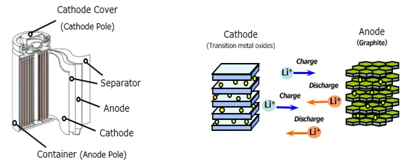
Lithium ions move from the positive (Cathode) to the negative electrode (Anode) during charging and from the negative to the positive electrode as the battery is discharged. Electrons move through an external circuit in the same direction as the lithium ions.
Battery Chemistry
Li-ion batteries are often named according to the composition of their positive electrodes. In this case an ANR26650M1-B cell is a Lithium Iron Phosphate it’s chemical name LiFePO4 short form LFP
Positive electrode (cathode) materials
Summary Table
|
Lithium Iron Phosphate: LiFePO4 cathode, graphite anode |
|
|
Voltages |
3.20, 3.30V nominal; typical operating range 2.5–3.65V/cell |
|
Specific energy (capacity) |
90–120Wh/kg |
|
Charge (C-rate) |
1C typical, charges to 3.65V; 3h charge time typical |
|
Discharge (C-rate) |
1C, 25C on some cells; 40A pulse (2s); 2.50V cut-off (lower that 2V causes damage) |
|
Cycle life |
2000 and higher (related to depth of discharge, temperature) |
|
Thermal runaway |
270°C (518°F) Very safe battery even if fully charged |
|
Cost |
~$580 per kWh (Source: RWTH, Aachen) |
|
Applications |
Portable and stationary needing high load currents and endurance |
|
Comments |
Very flat voltage discharge curve but low capacity. One of safest |
Table 1 Characteristics of lithium iron phosphate.
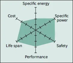
LiFePO4 batteries exhibit qualities that make them ideally suited for off-grid products where cost, safety, stability, and cycle life are primary requirements. They have lower energy density than competing Li-ion chemistries and a lower output voltage of 3.2V, but this is acceptable for most off-grid applications. Many successful off-grid products use LiFePO4 batteries.
Negatives Electrode (Anodes) Materials
Graphite and Carbon are used for the negative electrode. Lithium ions become intercalated in the carbon sheet structures when the cell is charged and released during discharge. When the cell is first charged, a solid electrolyte interphase (SEI) layer forms on the graphite surface. The SEI layer stabilizes the anode by preventing reactions between the graphite and the electrolyte. SEI layer integrity plays an important role in cell performance.
Cell: ANR26650M1-B
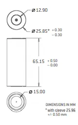
The name ANR26650 is given from the formation and dimension of the cell, It is it’s identification; thus a cylindrical with a diameter of 26mm and a height of 65mm
Battery Configuration and Charge and Discharge Characteristics
The circuit parameters can be modified to represent a specific battery type and its discharge characteristics.
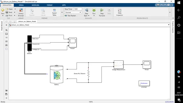
The screenshot above is a circuit in MATLAB of Lithium-ion battery model configuration in Simulink, consisting of battery model, resistor, voltage measurement, scopes, bus selector and powergui. Battery model Parameters are selected to match manufacturer’s specifications, in this case Datasheet is attached to compare the simulated results to product specifications
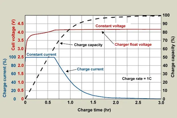
Proper charge control and protection circuitry is critical for Li-ion batteries. Overcharging a Li-ion battery can lead to a fire or explosion, and over discharging can permanently damage the battery. Li-ion batteries are charged in a constant-current charge at 0.5-1C until the battery reaches its maximum voltage, usually 3.3 V. After the ending voltage is reached, the battery is charged at constant voltage until the current drops below a threshold, between 0.02C and 0.1C, or for a fixed amount of time. If the battery is severely depleted, a slow charge (0.1C) is necessary to bring the voltage up to 2.5 cell. Accurate voltage regulation is critical for safely charging Li-ion batteries; the tolerance for overcharging can be 50 mV or less.
Battery pack capacity: 18 kWh
This model of battery pack consists of cells in series and parallel aimed for a capacity of 19.8KWh factoring in some tolerance on voltage regulation, safety, environment and other factors into mind. Series wiring is double voltage and same capacity, Parallel wiring is same voltage and double capacity.
Volts (V) x Amps hours (Ah) = Watt hour (Wh)
To get a total power energy of 19.8KWh, the Lithium battery pack voltage used is 125.4V and capacity of 157.5Ah.
125.4V x 157.5Ah = 19.8KWh
125.4V/3.3V = 38 cells in series
157.5Ah/2.5Ah = 63 cells in parallel.
Configured battery pack cells of 38S63P
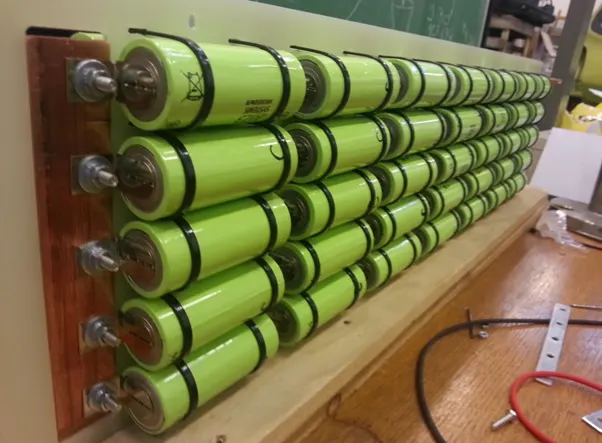
A complete Lithium-ion battery pack incorporated with Battery Management System
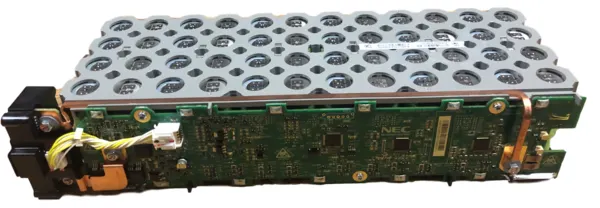
The functions of the BMS consist of monitoring the status of the battery cells (voltage, current, and temperature), monitoring state of charge (SOC) and state of health (SOH) to estimate the states of the battery cells, performing diagnostics, and communicating with diagnostic tools. Cell balancing is another important task carried out by the BMS, as we know multiple cells will be combined in series or parallel to form a battery pack. The cell voltage of all the cells should always be equal.
A circuit of Battery pack in MATLAB
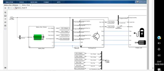
This example project can be used as a reference design to get started with designing Lithium Ion Battery Management System (BMS) with MATLAB and Simulink.
Project includes Simulink models for BMS Algorithms such as:
- State of Charge estimation using Extended Kalman Filter, Unscented Kalman Filter
2. Passive Battery Cell Balancing
3. State Machine for Pre-charging and Contactor Management
4. Fault Management - Over/Under Voltage, Over Current, Over Temperature etc.
5. Charge and Discharge Current Limit Calculations
To design and test these algorithms, project also includes files for
1. Li-ion Battery Cell Parameter Estimation
2. Battery Pack with 6 cells in series and 96 cells in series
3. Simulink Test files with test cases to test State Machine Logic
4. Linking requirements to Models
Safety
- Li-ion cells should always be charged according to the battery manufacturer’s specifications. Under no circumstances should cells be subject to overcharge, overdischarge, or short circuit.
Cells should not be subject to high temperature charging (>45°C) or low temperature charging (<0°C).
Cells should never be subject to mechanical abuse or stress
Cells should only be stored in a partially discharged state, typically between 20-40%.
Cells used in battery packs should be individually monitored and controlled by a battery management system (BMS) to prevent electrical abuse.
Battery packs should be designed to allow passive cooling of individual cells, and cell spacing should be designed to prevent thermal runaway from spreading cell-to-cell.