Project 1 Mechanical design of battery pack
Mechanical Design of Battery Pack:
Aim of the Project:
Battery pack capacity: 18 kWh
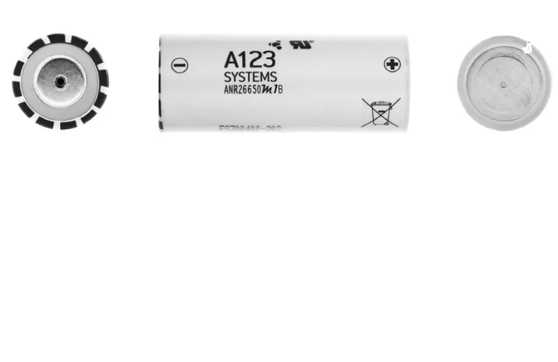
Cell: ANR26650M1-B
Prepare a detailed battery pack drawing along with its enclosure. State your assumptions.
ABSTRACT:
A battery pack thermal management system is provided that is comprised of at least one enclosure failure port integrated into at least one wall of a battery pack enclosure, where the enclosure failure port(s) remains closed during normal operation of the battery pack, and opens during a battery pack thermal runaway event, thereby providing a flow path for hot gas generated during the thermal runaway event to be exhausted out of the battery pack enclosure in a controlled fashion.
OBJECTIVE:
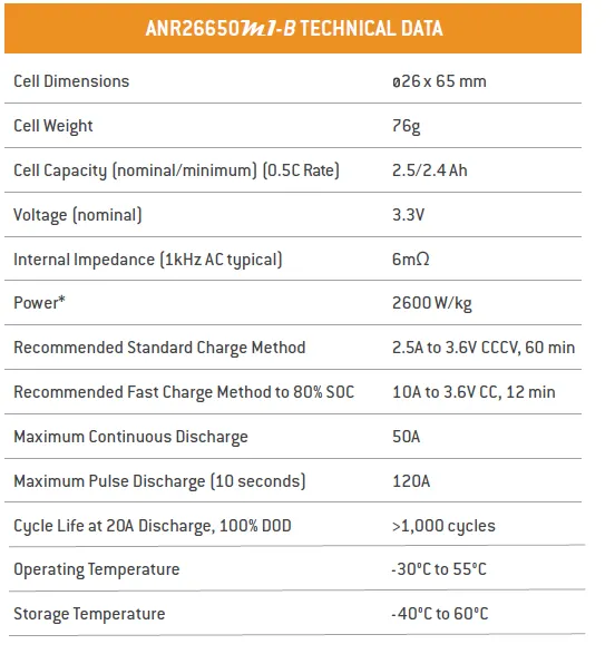
- Collecting the data of cell: ANR26650M1-B from Nanophosphate high power lithium-ion cell pdf.
- Calculating all electrical parameters for 18kWh battery pack.
- Calculating all physical dimensions for battery pack.
- Consider perfect enclosure for dimensions that we calculated for the battery pack.
Cell Design Methodology using ANR26650m1-B:
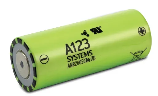
A123’s high-performance Nanophosphate® lithium iron phosphate (LiFePO4) battery technology delivers high power and energy density combined with excellent safety performance and extensive life cycling in a lighter weight, more compact package. Our cells have low capacity loss and impedance growth over time as well as high usable energy over a wide state of charge (SOC) range, allowing our systems to meet end-of-life power and energy requirements with minimal pack oversizing.
Nanophosphate Technology
A123 Systems’ low impedance Nanophosphate electrode technology provides significant competitive advantages over alternative battery technologies, including:
- Power: Our high-power, Nanophosphate products can pulse at high discharge rates to deliver unmatched power by weight or volume.
- Safety: A123 Systems’ Nanophosphate technology is designed to be highly abuse-tolerant, while meeting the most demanding customer requirements of power, energy, operating temperature range, cycle life, and calendar life.
- Life: A123 Systems’ Nanophosphate technology delivers exceptional calendar and cycle life. At low rates, our cells can deliver thousands of cycles at 100% Depth-of-Discharge, a feat unmatched by other commercial lithium ion cells.
Power
A123 Systems cells are designed to deliver high power in pulse and continuous applications. Figure 1 displays typical discharge curves showing that the voltage remains virtually flat during the discharges and the delivered AH capacity doesn’t change significantly, no matter what the rate of discharge.
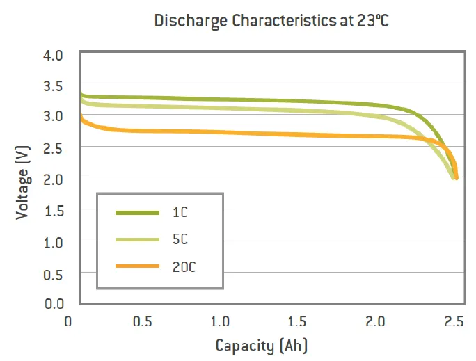
Figure1: 26650 Discharge Curve
Cell resistance changes with cell temperature. The warmer the ambient and/or cell temperature, the lower the resistance. Note that in Figure 5, the cells hold up voltages at cold temperatures less effectively than at ambient room temperatures. Voltages reach parity when the cells heat up to or beyond ambient room temperatures.
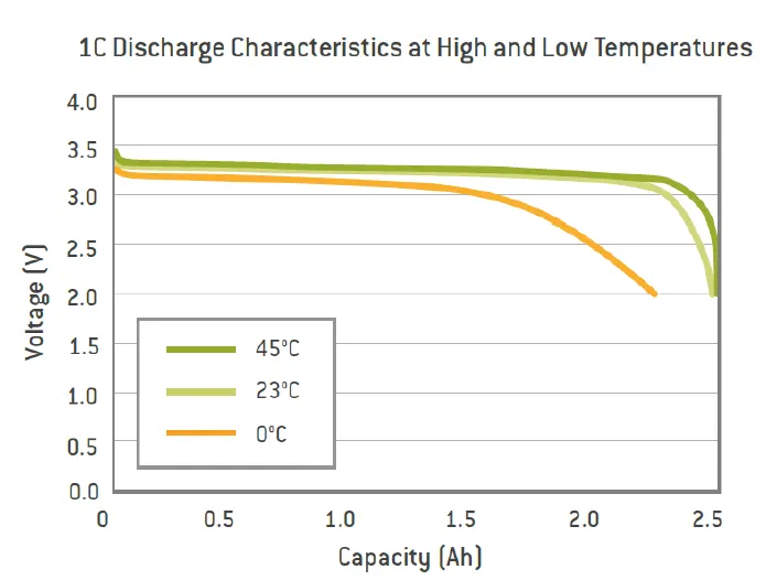
Figure2: 26650 Discharge Curves at Various Temperature
Safety
Proper handling and battery pack design must be followed to make sure the A123 Systems Nanophosphate cells operate safely. These cells can store significant amounts of energy, and (unlike most other types of cells) deliver this energy very quickly. Appropriate pack design must provide sufficient mechanical and environmental protection to ensure the cells operate within the proper voltage, current, and temperature limits.
The following minimum safety precautions must be followed at all times.Failure to follow the following safety instructions may result in personal injuries or damage to the equipment.
- Cells must not be subjected to ambient conditions or self-heating that result in a temperature in excess of 60°C during operation or while in continuous storage because they will either lose life or be rendered inoperable. Do not incinerate cells, or store or use them near open flames. Cells must not be punctured, ruptured, dented, or crushed. The pack design must likewise ensure this under normal operations or in a crash.
- Cell packaging must not be altered in any way.
- Cells must not be immersed or exposed to water or liquids.
- Never use pressure at the top and bottom of the cell to hold cells together in a way that leads to blocked cell vents. If the vents are blocked, the gas cannot exit the cell in case of cell failure. Cells shall be mounted in the application, in a way that will not interfere with the vent function on the cell.
- If the cell or battery emits smoke or flares, ventilate the area immediately and avoid breathing the fumes. See MSDS for additional precautions.
- Cells must not be subject to reverse polarity or short circuited. Individual cell fusing is required in pack designs with cells in parallel to be compliant with UN 38.3, US-DOT and other international shipping regulations. Cells must not be charged or discharged outside the operating temperature range in the datasheet, and reduced charging limits must be followed for lower operating temperatures.
Life
A123 Systems cells offer long cycle and calendar life, with minimal impedance growth over the life of the cells. The ambient temperature cycle life graphs in Figure 3 demonstrates that these cells also offer extended calendar life, even at elevated temperatures.
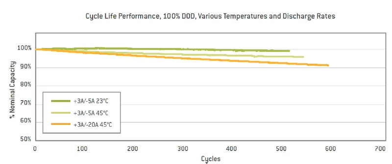
Figure 3: 26650 Cycle Life
Application:
A123 Systems’ cells can be used in many different applications, ranging from Hybrid Electric Vehicles (HEVs) to embedded systems to backup storage devices. This guide cannot cover all possible uses, pack designs and conditions for these cells; therefore, you must make sure the pack design is suitable for your application, and then design and test accordingly. Cells can be combined together either in series or in parallel to achieve higher operating voltages and capacities, respectively.
Series Strings:
Cells combined in series strings can achieve higher operating voltages by connecting the positive terminal of one cell to the negative terminal of the next cell. Connect strings of series cells using their current collection tabs in a manner similar to that illustrated in
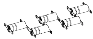
Figure 4: Cells Connected in Series
Two cells in series: 2 x 3.3V = 6.6V (nominal)
Three cells in series: 3 x 3.3V = 9.9V (nominal)
Parallel Strings
Cells combined in parallel strings can achieve higher operating capacities by connecting like-polarity terminals of adjacent cells to each other. Connect strings of parallel cells using their current collection tabs in a manner similar to that illustrated.
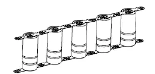
Figure 5: Cells Connected in Parallel
Two cells in parallel: 2 x 2.5Ah = 5Ah (nominal for 26650 cells)
Three cells in parallel: 3 x 2.5Ah = 7.5Ah (nominal for 26650 cells)
Charging or Recharging Cells or Strings:
- When charging or recharging Nanophosphate cells, the charger should apply a constant current (CC) charge followed by a constant voltage (CV) charge.
- To achieve maximum life, reliability, and safety, A123 Systems recommends using cell balancing circuitry during cell charging to prevent an increasing spread between highest and lowest battery voltages.
- If the cell string has 10 cells in parallel (10P), and the recommended charge current per cell is 3A, then the charge current for this string is 30A: (10 cells, parallel) x (3A) = 30A
- If the cell string has 10 cells in series (10S), and the recommended charge voltage per cell is 3.6V, then the end of charge voltage for the string is 36V: (10 cells, series) x (3.6V) = 36V .
- If the cell string has 10 cells in series and 3 cell strings in parallel (10S-3P), the recommended charge voltage per cell is 3.6V, and the recommended charge current per cell is 3A, then the charge current and charge voltage for the string is 9A and 36V: (10 cells, series) x (3.6V) = 36V (3 cells, parallel) x (3A) = 9A .
- Once the end of charge voltage has been reached, apply a constant voltage hold at this voltage until the current decays to near-zero. This process charges the cells to 100% state of charge (SOC). Refer to Figure 6 for an illustration.
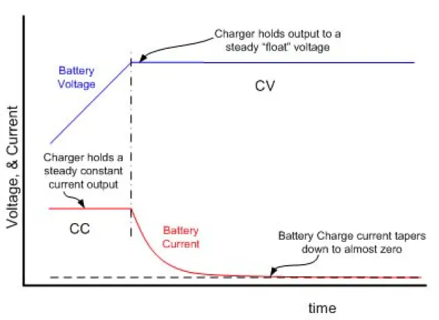
Figure 6: Battery Voltage and Current During Recharge
Battery Packs (also known as Energy Storage Systems (ESS) and battery modules) should be designed to protect and replicate the individual cell performance of multiple cells in the pack. This means providing mechanical protection and integrity, thermal stability, and electrical protection and performance.
Mechanical Connection and Protection:
Design mechanical interconnects to prevent accidental short circuits. Size these mechanical interconnects to carry the expected maximum rated current for both the maximum time and ambient temperature in which the pack is expected to operate.
Cell Interconnects:
Size cell interconnects for the expected maximum current carrying capability. Improperly sized tabs could heat up excessively, resulting in even higher resistivity. For reliable welded connections at the terminals, A123 Systems recommends either pure nickel tabs or nickel-clad copper tabs. In addition, other alloys afford both the weldability, strength and low resistance, which are all desirable features of a good interconnection. Cell interconnects (tabs) should be neither soldered on the end caps nor attached using extreme heat. A123 Systems recommends tabs be resistance or laser-welded to both ends of the cells. Resistance welding provides a constant current for a specified period of time through a salient feature in the weld tab. These parameters can be specified and regulated for a consistent high-quality weld every time.
Allowing the Cell to Vent in a Fault Condition:
The cell vents, located on the end cap(s) of the cells (on the POSITIVE side of the cell), should not be blocked by any mechanical means. Blocking the cell vent and then sufficiently abusing the cell so as to build up pressure in the cell prevents the cell from properly venting. An ESS designed to install cells end-to-end needs at least 1 mm of space between the cells to allow the vent to open under fault conditions. Refer to Figure 7 as an example.
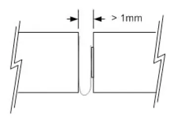
Figure 7: End-to-End Cell Spacing
Cell Insulation:
The outside case of the 26650 and 32113 is electrically connected to the positive end (cathode) of the cell. Take care to keep this surface electrically-isolated from any electrical bus bar or mechanical support that may be of different voltage potential. Insulation, such as tapes, shrink wraps, or sleeves, must have at least a 150 °C melting point. This helps ensure that the cells do not short circuit to each other in a high temperature fault condition, which could cause even more widespread damage.
Cell Support:
Secure the cells in place by supporting their outside cases, not their terminal ends. The vibration induced between the terminal ends and the rest of the case has been shown to be detrimental to the life of the cell, causing internal and external cell damage. The intercell terminations must be light enough not to cause vibration-induced damage to the cell.
Cell Protection:
In addition to being supported, protect cells from exposure to corrosive substances and oxidizing catalysts, such as dust and moisture. The necessary level of protection for cells in a battery pack varies depending on the intended application. For example, a battery pack designed for use in an HEV must have an enclosure that isolates cells from shock and vibration, protects them from dirt and debris, as well as shielding them from other environmental dangers, such as salt spray. Unless it is hermetically sealed, even a sealed enclosure is subject to pressure differentials between its insides and the ambient, causing minute amounts of air exchange. Therefore, over time, some moisture may accumulate and condense on inside surfaces. An ESS designed to be sealed from the environment (from dust, moisture, and VOCs) must have a way to benignly drain off whatever condensate does manage to leak into it. In addition, enclosures protecting cells must work with the thermal management system to achieve optimum durability and safety of the battery pack. For example, a poor choice of materials for the enclosure, combined with insufficient cooling and controls, may cause the battery pack to overheat.
Thermal Management:
A123 Systems’ cells operate throughout a wide temperature range; however, they are most effective between 10°C and 50°C. The temperature differential between the coolest cells and the hottest cells should be no more than 10°C. Careful attention to thermal management is necessary to keep the cells operating at peak efficiency and avoiding fault conditions. In most cases, this implies a cooling system. There are certain applications - such as HEV vehicles operating in cold climates - where a heater is beneficial to keeping the cells operating in their optimal range.
Electrical:
When joining cells together, A123 recommends using a Battery Management System responsible for carefully monitoring cell voltage, current, and impedance. The BMS may be implemented as discrete circuitry or through a microcontroller.
Cell Monitoring:
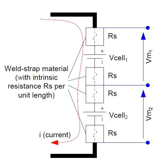
To ensure optimal performance, safety, and durability of the pack, the Battery Management System must monitor the voltage of each individual series cell in a battery string.Take care to place the voltage monitoring connections in such a place that they are not affected by high currents going through the interconnection elements.
The diagram below depicts an optimal positioning of the voltage monitoring contact points in an idealized setting:
In this case, Vm1 = Vcell1 – 2 x i x Rs and Vm2 = Vcell2 – 2 x i x Rs. The result of Vm1 – Vm2 would be exactly what is desired, and that being Vcell1 – Vcell2.
Battery Pack Calculation:
Battery pack is the motive source in electric vehicle. Designing of battery pack is one the important section in EV designing and battery pack calculation depends on several factors. Normally here we calculate and design battery pack according to 18KWh Capacity.
- Volume of the cell: for the calculation of the volume of the cell we use the formula of volume of cylinder.
so the formula is:
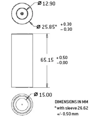
From datasheet of cell, we have ‘r’ and ‘h’ values,
R=0.013m and h=0.065m
Volume of the cell= 3.14*(0.013)^2*0.065
= 0.0000344929
The volume of the cell is 0.0000344929
Basically, the value of the volume of the cell is used to find out the total volume of the battery pack.
Cell energy= Cell capacity(Ah) * Cell voltage(V)
= 2.5 * 3.3
= 8.25 Wh.
Cell energy is 8.25Wh
The value of a single cell is used to calculate the total energy of the battery pack
Single cell energy density = single cell energy/volume of each cell
= 8.25 / 0.0000344929
Single cell energy density = 2,39,179.6572 Wh/
Battery pack assumptions:
There are 50 cells are in series and 44 cells are in parallel, and we used ANR26650M1-B cells for battery pack.
Battery pack calculation:
Now we calculate how parallel, series cells required for battery pack.
Total no. of cells = no. of cells in parallel * no. of cells in series
= 50*44
=2200
Total no. of cells = 2200
Voltage= no of cells in series * nominal voltage
= 50*3.3
=165V
The total value of voltage is 165V.
Current= No of parallel cells* cell capacity
= 44*2.5
= 110Ah
The total value of current is 110Ah.
So now we can calculate total energy of battery pack, and also understand our required satisfied or not.
Energy = Voltage*Ah
= 165*110
=18150WAh
The total value of energy is 18150WAh.
So our requirement is satisfied.
Now we have calculate total no of cells and volume of single cell so we can calculate the total volume required for battery pack.
Total volume = no. of cells * volume of single cell
= 2200*0.0000344929
= 0.07588438
Total volume required for battery pack is 0.07588438
We have single cell weight from that we can calculate total weight of battery pack.
Weight= no. of cells* weight of single cell
= 2200*0.076
= 167.2kg
Weight of battery pack is 167.2kg.
Energy density = volume*battery pack energy
= 0.076*18150
= 1,377.3 kWh/m^3
Energy density is 1,377.3 kWh/m^3.
Now we can make the physical battery pack. All the required data for construct the battery pack available here.
Battery pack assembling Part:
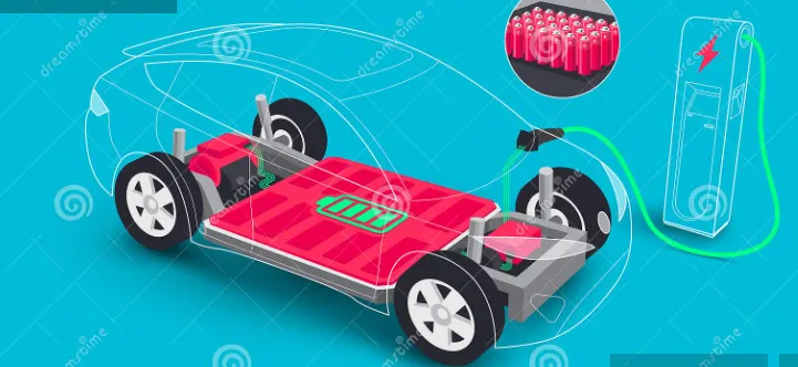
Lithium-ion battery pack composed of battery modules provide power for the electric vehicles. To ensure that lithium-ion batteries in battery modules are protected carefully, a battery holder was designed to provide support and protection for each lithium-ion battery. When the vehicles are at working, the battery pack will be affected by harsh environments, such as shocks due to road bumps and changes due to the road surface conditions
Battery Cell holder:
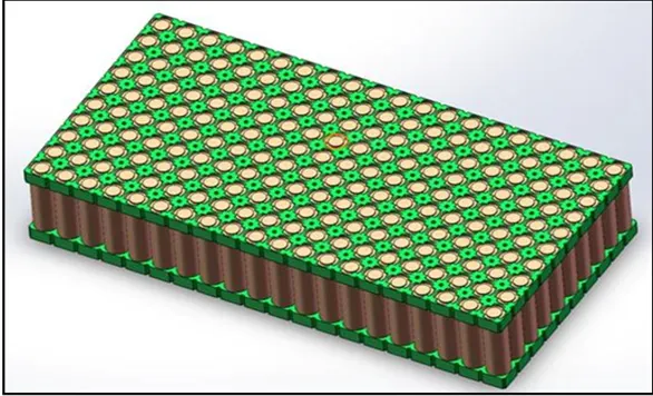
The safety of vehicle largely lies on the stabilization of the battery pack, and the stabilization of the battery pack rests on the mechanical performance of the battery holder, for instance the capability to resist deformation and defy vibration. Furthermore, the lightweight of electric vehicles is still the primary method for saving energy, because lightweight can increase the service life of the battery pack while it can also increase the mileage of the vehicle. In this study, a composite design optimization method was proposed to optimize the mechanical properties of the battery holder (minimization of mass, minimization of the maximum deformation, and maximization of minimum natural frequency). The proposed method includes four steps. In the first step, the finite element model under load was obtained based on the static analysis. The natural frequency and the geometric volume of the battery holder were obtained Based on the modal analysis.
Battery Pack Components for EV:
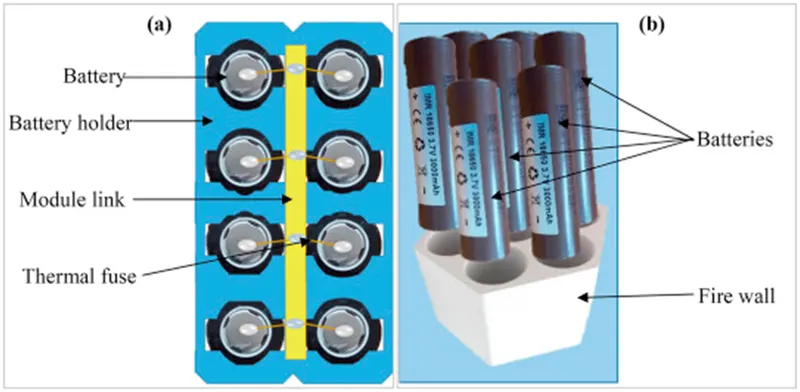
The lithium-ion batteries in electric vehicles (EVs) present very different material demands at the cell- and pack-level compared with the internal-combustion engine (ICE) vehicles they replace. Whilst ICE drivetrains heavily rely on aluminium and steel alloys, Li-ion batteries utilise a great deal of materials such as nickel, cobalt, lithium, copper, insulation, thermal interface materials and much more at a cell- and pack-level. The markets for these materials will see a rapid increase in demand that would not have been present without the take-off of electric vehicle markets.
- Interconnects
- Housings
- Thermal management
- Thermal interface materials
- Inter-cell pads and insulation
- Fire-retardant papers/blankets/coatings
BATTERY PACK PLASTIC ENCLOSURES:
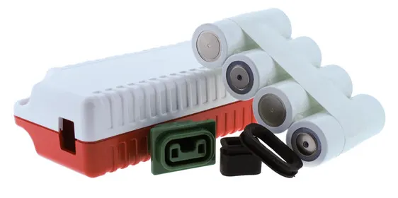
- Customers are often unfamiliar with battery regulatory requirementswhich can lead to complications during the design of plastic enclosures. Understanding some of the design and management elements will help avoid production process complications. With any enclosure, the most important aspect is that the enclosure must be able to support the battery itself. It must also pass rigorous tests - especially when associated with transportation safety certifications.
- One of the first steps once a customer has approached a manufacturer is to determine the level of design the customer intends and if it is a full design or partial. A full design would allow the manufacturer to be in full working knowledge of the project from the start. The creation of CAD files, progressive meeting schedules, approval stages, and the production volume will be established based on the need and depth of a full or partial design. The production volume will determine the level of tooling required. Tooling can raise costs and/or extend the time of a project's completion. The intention is to always get the design completed first time through because of time involved, cost, and tooling. Most importantly is meeting the transportation certification requirements and the customer's look and feel of the design.
Sealing the Plastic Enclosure:
- After the internal components have been secured, the enclosure has to be sealed. Take note that sealing the enclosure is part of the final assembly. Ultrasonic wielding is a method that uses high-frequency acoustic vibrations to generate heat. The heat melts the material voiding any need for screws or bolts.
- Ultrasonic wielding is a robust and economically sound solution. Using screws or bolts are still a viable option. However, having access to surface screws or bolts may be good for repair but also easy access for end users to alter the application. Lastly, glue is another adequate sealing solution, typically used in lower quantities.
Securing Internal Components:
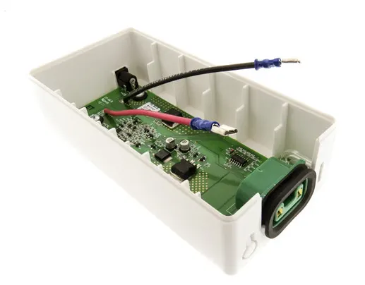
Concerns with internal components shifting during use have options to ensure parts stay in place. The actual product and how it will be used, handled, and stored determines how the enclosure will be created. Once there is an understanding on the actual product details, the enclosure would be designed internally. Procedures for securing internal parts include RTVs, designing ribs, combination of glues, and in most cases foam spacing - all of which help hold parts in place and minimize any shifting.
Conclusion:
In this project i have learn about all the mechanical component required for the battery pack. i have calculate battery parameters according to given power requirement. learn about battery safty and packing precaution.