Project 1 Mechanical design of battery pack
EV - 21 PROJECT 1
A123’s high-performance Nanophosphatelithium iron phosphate (LiFePO4) batterytechnology delivers high power and energydensity combined with excellent safety performance and extensive life cycling in alighter weight, more compact package. Our cellshave low capacity loss and impedance growthover time as well as high usable energy over a wide state of charge (SOC) range, allowing our systems to meet end-of-life power and energy requirements with minimal pack oversizing
COMMERCIAL SOLUTIONS
Advanced lead acid replacement batteries for:
Datacenter UPS
Telecom backup
IT backup
Autonomously guided vehicles (AGVs)
Industrial robotics and material handling equipment
GOVERNMENT SOLUTIONS
Military vehicles
Military power grids
Soldier power
Directed energy
GRID SOLUTIONS
Frequency regulation
Renewables integration
Reserve capacity
Transmission and distribution
TRANSPORTATION SOLUTIONS
Hybrid, plug-in hybrid and electric vehicle battery systems for:
Commercial vehicles
Off-highway vehicles
Passenger vehicles
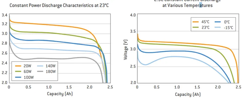
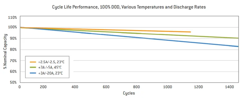
ANR26650M1-B Specifications
Nominal Ratings
Voltage: 3.3 Volts
Capacity: 2.5 Ah
Energy: 8.25 Wh
Specific Power: 2600 W/kg
Impedance (1KHz AC Typical) 6 mΩ
Cycle Life at 1C/1C, 100% DOD: > 4000 cycles
Cell Type: 26650 Lithium Ion Power Cylindrical Cell
Discharging
Max Continuous Discharage: 50 A
Max Pulse Discharge Current >50% SOC (10s): 120 A
Minimum Voltage: 2 Volts
Temperature: -30ºC to 55ºC
Charging
Recommended Standard Charge: 2.5 Amps
Max Charge Rate: 10 Amps
Max Pulse Charge Current <50% SOC (10s): 25 A
Float Voltage: 3.45 Volts
Recommended charge V & Cut-off Current: 3.6 Volts, taper to 125mA
Temperature
(reduce charging current to 250mA when under 0ºC): 0ºC to 55ºC
Mechanical
Diameter: Ø25.96 +/- 0.5 mm (1.0")
Length: 65.15 +/- 0.5 mm (2.6")
Mass: 76 g
ABOUT CELL :
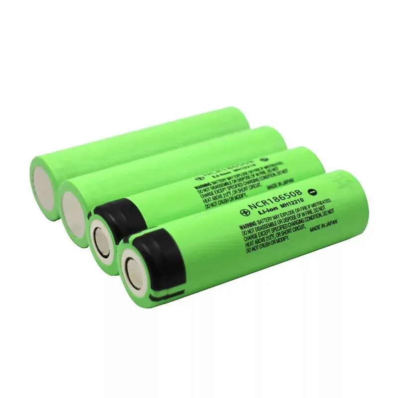
The ANR26650M1-B is the next generation of A123 system pioneering 26650 cylindrical cell now with greater power and energy density and lower impedance. This versatile lithium ion cell is suitable for a wide variety of applications and system designs
ABOUT MODULE :-
Battery management system (BMS) is any electronic system that manages a rechargeable battery (cell or battery pack) such as by protecting the battery from operating outside its safe operating area monitoring its state and calculating secondary data reporting that data controlling its environment
ABOUT BATTERY PACK :-
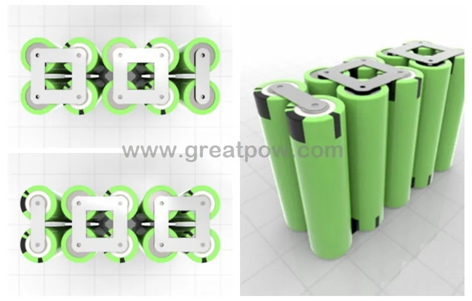
A Battery pack is a set of any number of identical batteries or individual cells they ay configured in series parallel or mixture of both to deliver the desired voltage ,capacity or power density
Mechanical design of battery pack :-
Mechanical pack design addresses key requirements - from durability and crashworthiness to requirements for volume production like manufacturability, serviceability and recyclability - in an early stage of the development process. AVL is your ideal partner for the development of battery packs
the high voltage battery it is one of the most important component of a battery electric vehicle the battery parameters have significant influence on other components and attributes of the vehicle
maximum traction motor torque
maximum regeneration torque
vehicle range
vehicle total weight
vehicle price
pretty much all major aspects of a pure electric vehicle depend on the parameters of the high voltage battery for our electric vehicle battery design we are oing to start from 4 core input parametres
chemistry , voltage
average energy consumption of the vehicle on a drive cycle
vehicle range
Electrical Components
- Cell connections
- BMS
- Shunt
- Harness
- Relay, Contactors, MOSFETs
- Temperature Sensors
Mechanical Components
- Enclosure
- Cooling System
- Seals, Glands, Packages
-
Desired Characteristics of a Battery Pack/Module:
Light Weight
Long Lasting
Optimum cost
Waterproof
Considerations in Battery Pack Design
Electrical /Chemical
- Connections
- Connector Selection
- Harness Design
- Wire Gauge Selection
- EMI/MC
- Variation in characteristics due to temperature
Thermal
- Safety
Steps involved in Battery Pack Design:
- Understand requirements
- Select cell chemistry, type, capacity etc.
- Select other components to meet requirements.
- Select wire AWG ratings as per the current.
- Assemble in CAD to see fitment possibility.
- Run structural, thermal and CFD analysis.
- Decide heat management requirements.
- Change design if needed to accommodate the Heat Management System.
- Make CAD and run CAE Analysis.
- Get prototype manufactured
THERMAL
- Integrity of Components
- Vibration
- Sealing
- Ingress Protection
battery consists of one or more electrochemical cells which are converting chemical energy into electrical energy during discharging and electrical energy into chemical energy during charging the type of elements contained within a battery and chemical reactions during the discharging and charging events dfine the chemistry of the battery
battery cell consists of five major components : electrodes - anode and cathode , separators ,terminals electrolyte and case or enclosure for automotive applications there are different types of cells used
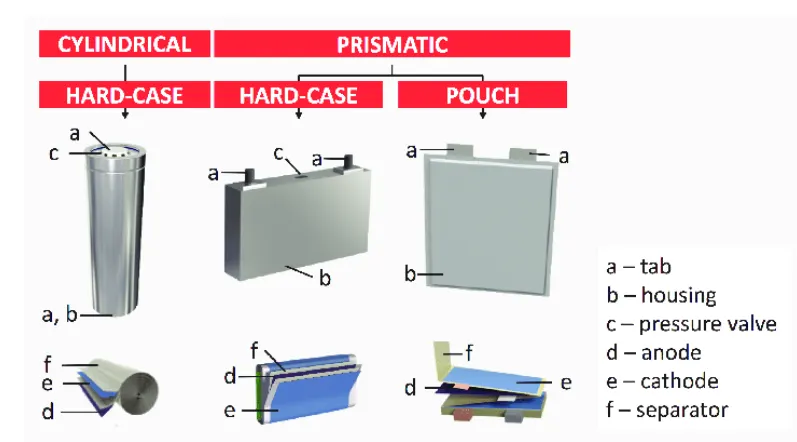
individual battery cells are grouped together a single mechanical and electrical unit called battery module the module are electrically connected to form a battery pack
there are several types of batteries used in hybrid and electric vehicle propulsion systems but we are going to consider only lithium ion cells the main reason is that the lithium ion batteries have higher specific energy and specific power compared with other types
EV - DESIGN BATTERY CALCULATION
Assumptions :-
Battery energy = 18kwh
voltage to run the vehicle = 400V
Number of cells (N) = energy / nominal voltage * capacity
N = 18000 / (3.3*2.5)
N= 2182
we need a minimum of 2182 cells to get the 18kwh energy now based on that we need to decide configuration - series and parallel
in series configuration capacity remains same and voltage will be the sum of individual cell voltage
in a parallel configuration the voltage remains same and capacity accumulates and we assumed 400V need to run the vehicle
the nominal voltage of one cell = 3.3V
number of series cells required to produce 400V
Ns = voltage required / nominal voltage of one cell
Ns = 400 / 3.3 = 121.22 = 122
122 cells are connected in series will generates the 400 volts and the capacity of the whole module will be 2.5Ah
now we need to find the number cells which will be connected in parallel configuration
Np = cell in parallel = total cell / Ns
Np = 2182 / 122 = 17.8 = 18
hence we take 18 cells for each parallel row although it exceeding the required capacity
cell architecture = 122series and 18 parallel = 122S18P
Battery capacity :-
we know parallel configured cell multiplies individual cell capacity
capacity = parallel cell row * individual cell capacity
capacity = 18 * 2.5 = 45Ah
Current supplied by the battery :
we have already calculated battery capacity which is 45ah means it going to supply 45Ah which can be considered as c-rate
Range : -
lets powertrain energy consumption = 100 wh/km at70 % powertrain efficiency
Range = capacity / energy consumed per km
Range = 18000 / 100 = 180km
so our vehicle will be able to cover around 180km with current parameters
Internal Resistance of the battery : -
the entire resistance encountered by current as it flows through a battery from the negative terminal to positive terminal is known as internal resistance of the battery
Battery dimensions :-
ANR26650 cell has diameter 26mm and height 65mm on the basis of that we need to decide battery size of battery casing
Length of casing (L) = number of cells at series * cell diameter + margin at both side of cell(4) + clearance at side (diameter of edged cell + margin)
L=122*30+60
L=3720mm
breath of casing (B) = number of cells at parallel * (cell diameter (26) + margin at both sides of cell(4) + clearance at side (diameter of edged cell +margin)
B= 18*30+60
B=600mm
height of casing (H) = 65+35 (height of cell + margin for wiring cell holders and metal strips )
H=100mm
Weight of the battery pack :-
cell weight = 76g
number of cells = 2182
battery pack weight (W) = cell weight * number of cells + weight of accessories
W = 76 * 2182 +4.5
170.3 Kg
ASSEMBLY OF THE BATTERY PACK
component of the battery pack
1.2182 cells
2. nickle strip
3. PVC heat sink film
4. spot welder
5. connected
6. cell holder
7. solder
Step 1 :
the first step is to start snapping the square cell holder together one can use the cell terminal block but they will take more space than a hexagonal block
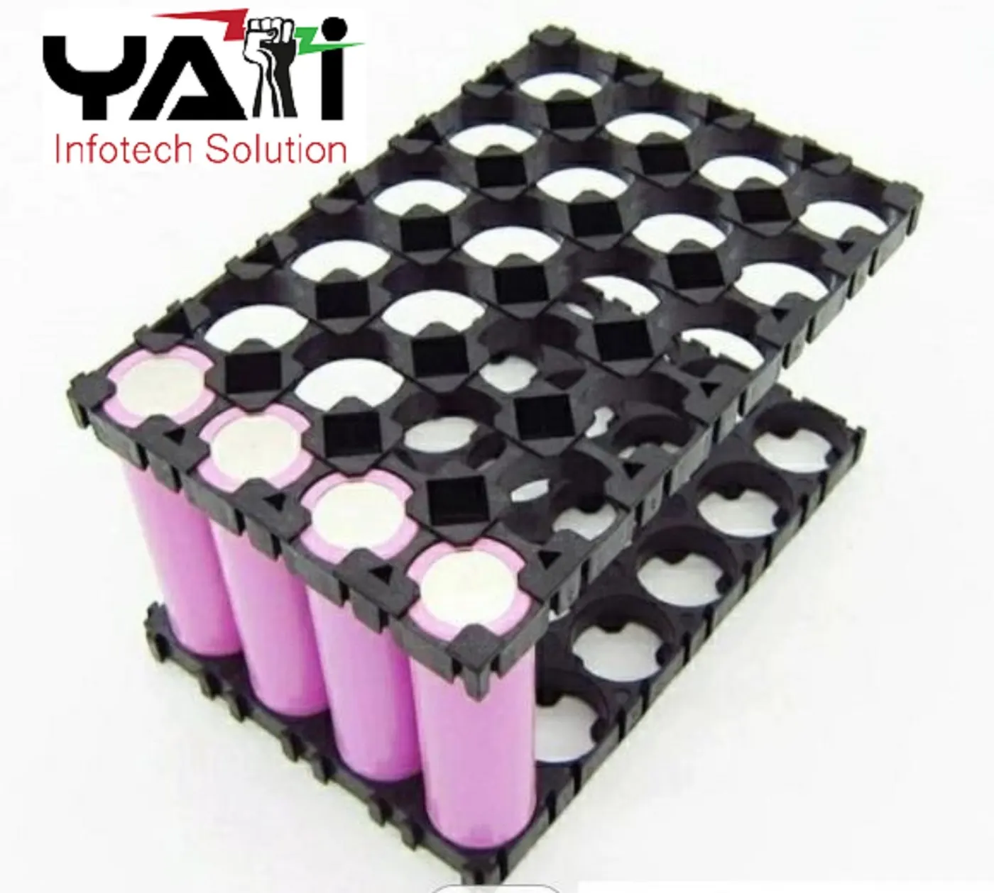
Step :2
placing the cells in the holder matrix place all the cells in the holder and put the second holder in the place
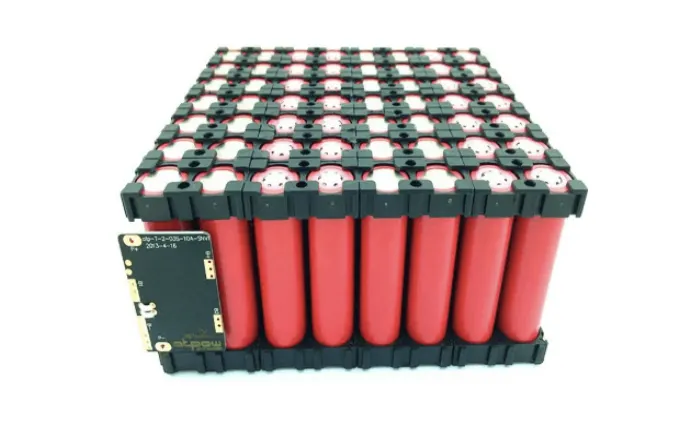
Step 3:-
now we will be connecting the cells with nickel strips using the spot welding process the series connection will be made by connecting the positive terminal of the cells to the negative terminal of the cells to be negative terminal the prallel connection will be made by connecting the same terminal connecting the complete matrix of the cell together

Step 4 :-
connecting the heat sink to the battery pack now we will soldering the battery wire now the internal structure of battery pack is assembled and all the terminals connected as per the connections
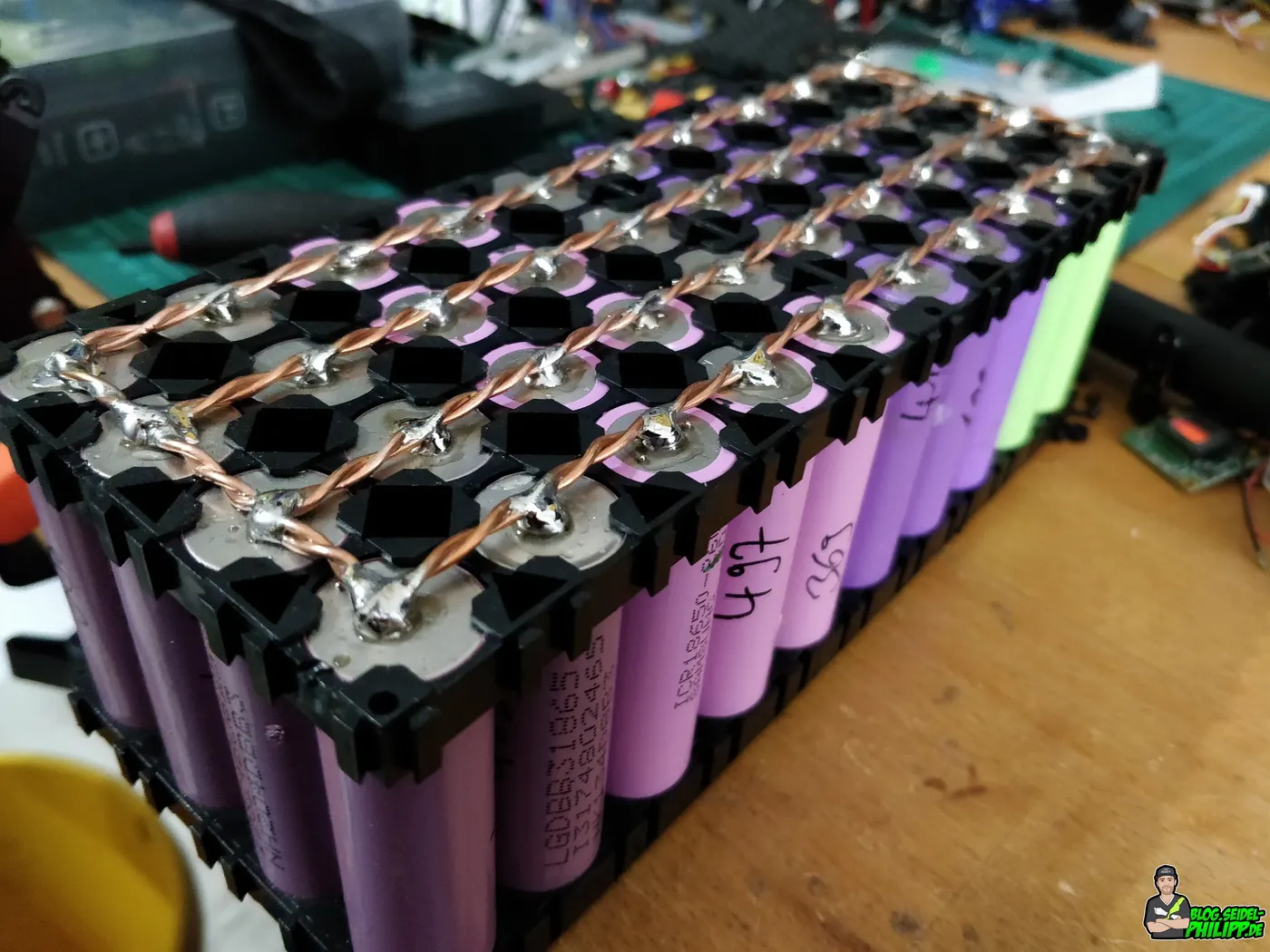
Step 5 :-
connect the balancing pin wire to the battery management system
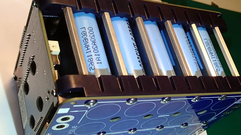
Step 6:-
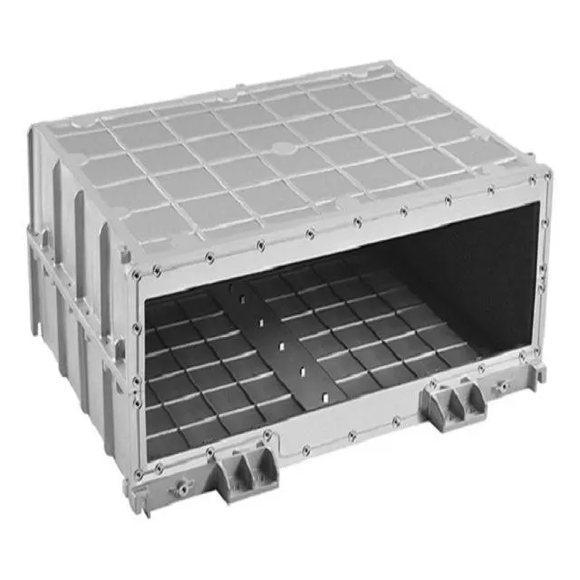
after the battery management system the next and final step is to place the enclosure for the battery pack this is the final battery model created
CONCLUSION :-
the design calculation for the battery pack was carried out and calculated and a table has made for the same the steps involved in the making of the have been listed out