Project 1 Mechanical design of battery pack
Aim:- To prepare a detailed battery pack of Cell : ANR 26650M1-B The battery capacity is 18kwh
Answer:
About the batteries used in Ev:
- Here the electric vehicles are increasing in the market is g increasing day to day there is considerable growth in the production of lithium-ion batteries.
- As it is the electrical source for the EV.
- The ithium-ion battery or Li-ion battery is a type of rechargeable battery in which the lithium ions move from the negative electrodes through an electrolyte to the positive electrode during discharge
- Then they back when charging.
- The Li-ion batteries use an intercalated lithium compound as the material at the positive electrode is graphite at the negative electrode
- This Lithium-ion batteries are made use of various different electrodes.
- And The most common material use is lithium cobalt oxide and graphite which are most commonly found in portable electronic devices such as cellphones and laptops.
- So the Lithium manganese oxide and lithium iron phosphate are also used as cathode materials.
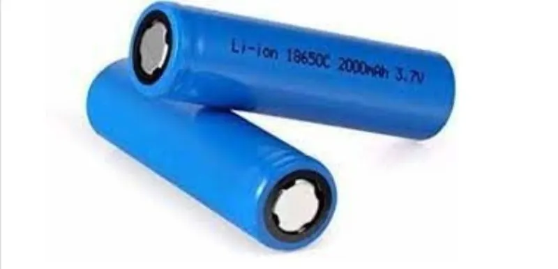
Internal structure:
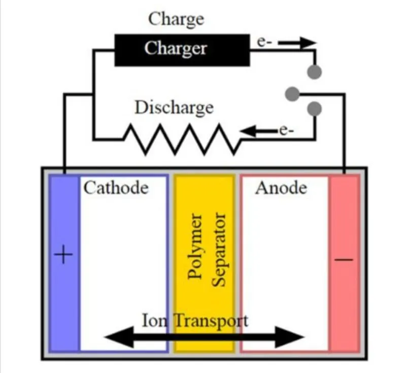
- Here the battery is made up of an anode, cathode, separator, electrolyte, and two current collectors (positive and negative).
- Here mainly The anode and cathode store the lithium.
- Which the electrolyte carries positively charged lithium ions from the anode to the cathode through the separator.
- So the movement of the lithium ions creates free electrons in the anode which creates a charge at the positive current collector.
- So here The electrical current then flows from the current collector through a device being powered to the negative current collector.
- So The separator blocks the flow of electrons inside the battery.
Charge and discharge:-
- When the battery is discharging and giving an electric current
- the anode releases lithium ions to the cathode gives the generating a flow of electrons from one side to the other.
- But When plugging in the device the reverse process is happens
- where the Lithium ions are released by the cathode and received by the anode.
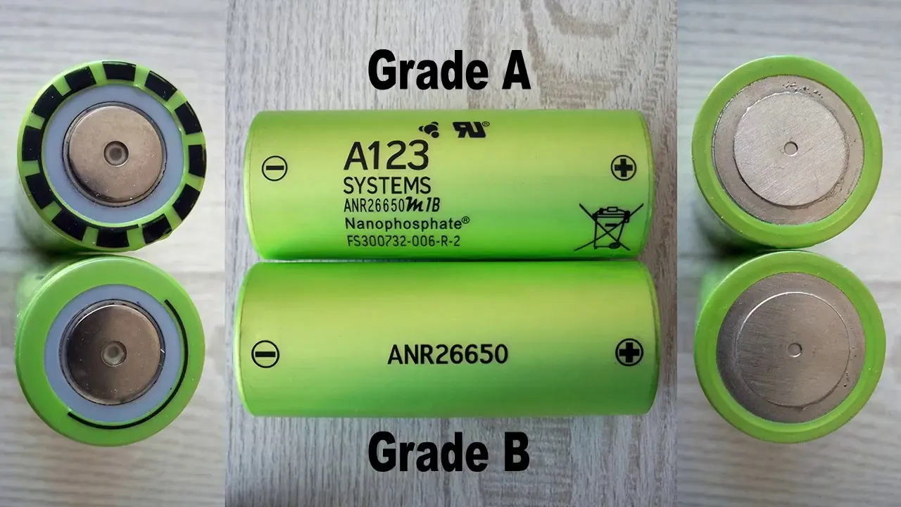
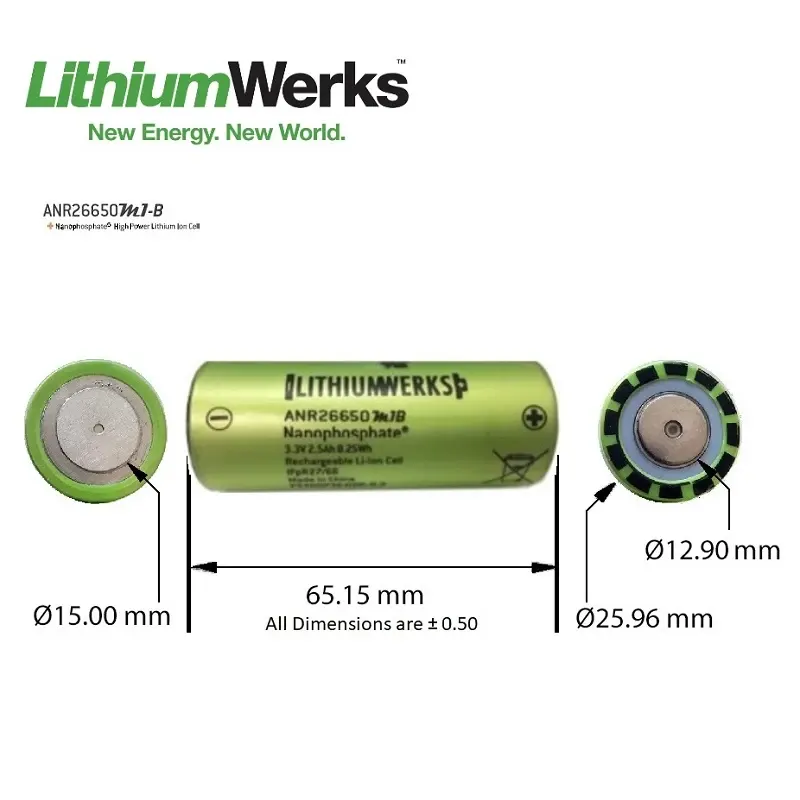
ANR26650M1-B (Nanaophosphate High Power Lithiumlon Cell):
- Here the high-performance Nanophosphate lithium iron phosphate (LiFePO4) battery technology delivers high power and energy density combined with excellent safety performance and extensive life cycling in a lighter weight more compact package.
- So Our cells have a low capacity loss and impedance growth over time as well as high usable energy over a wide SOC range allowing our systems to meet end-of-life power and energy requirements with minimal pack oversizing.
Applications of this battery:
There are different applications of Lithium-ion cells some of them are:
a) Commerical solutions:
- This is the large-scale application for the battery where high power is required.
- Used in Datacenter UPS
- Used in Telecom backup
- Used in the Industrial robotic and material handlin gequipment
b) Government solutions
- Used in Military vehicles
- Aslo for military power grids
C)Grid solutions:
- Used as Frequency regulation
- used in Renewable integration
- It is aslo used as REverse capacity
- used for Transmission and distribution
d) Transportation solutions:
- Used in Plug-in hybrid vehicles hybrid carsl electric vehicles
- used in Commercial vehicles
- For passenger vehicles.
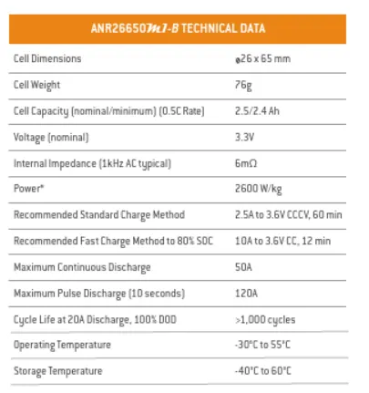
So here The performance of the cell is given in the datasheet that is referred to for this project.
The images show the power discharge current discharge and the life cycle of the cells used for the battery pack.
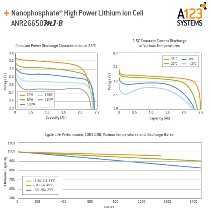
Here we can see that voltage capacity of the battery for different power ratings:
Design and calculation of the cell:
All the required parameters are taken from the data sheet
Process for calculation:
- Here The capacity of the battery pack is taken as 18kWh.
- So by making a high voltage battery pack many cells are arranged in a particular pattern and sequence to improve the voltage and the power rating of the cell
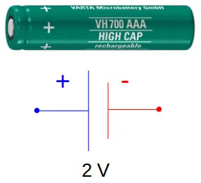
- The Individual battery cells may be grouped in parallel or series as modules.
- So by Further battery modules can be connected in parallel or series to create a battery pack.
- This is mainly Depending on the battery parameters where there may be several levels of changes
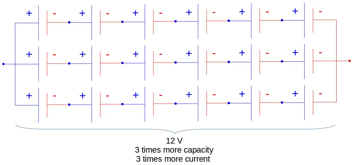
- So The total battery pack voltage is determined by the number of cells in series. So For example let us take the total string voltage of 6 cells connected in series will be the sum of their individual voltage.

- So Now in order to increase the current capability of the battery capacity
- The more strings have to be connected in parallel.
- Now For example 3 strings connected in parallel will triple the capacity and current capability of the battery pack.
- Now here for calculating the required battery pack based on the cell manufacture data provided.
- The below calculations are done:
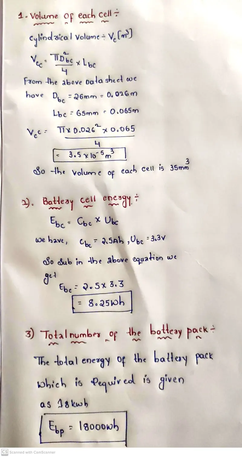
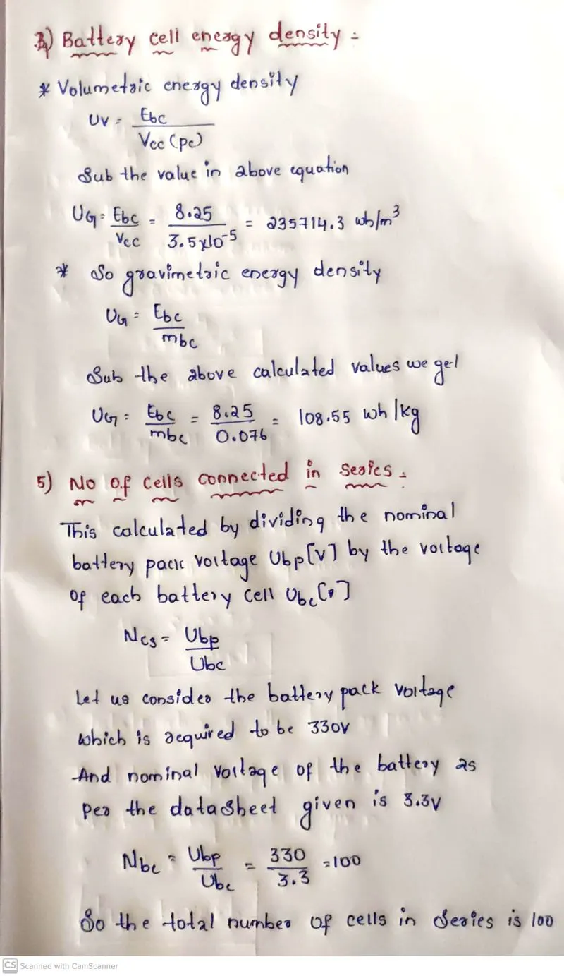
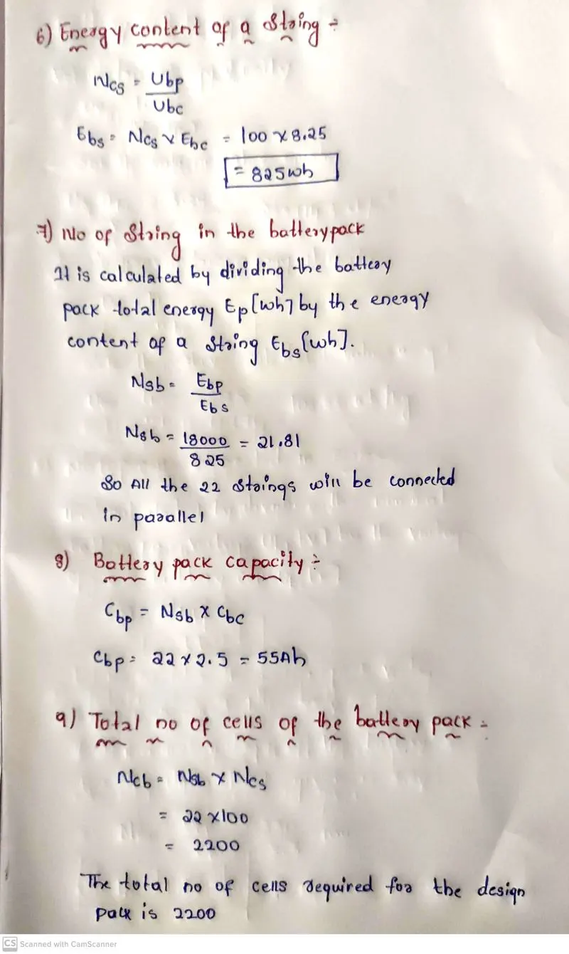
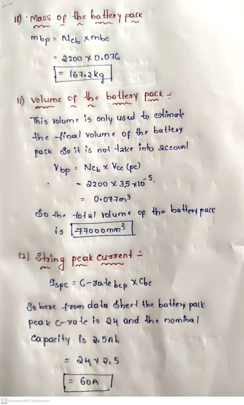
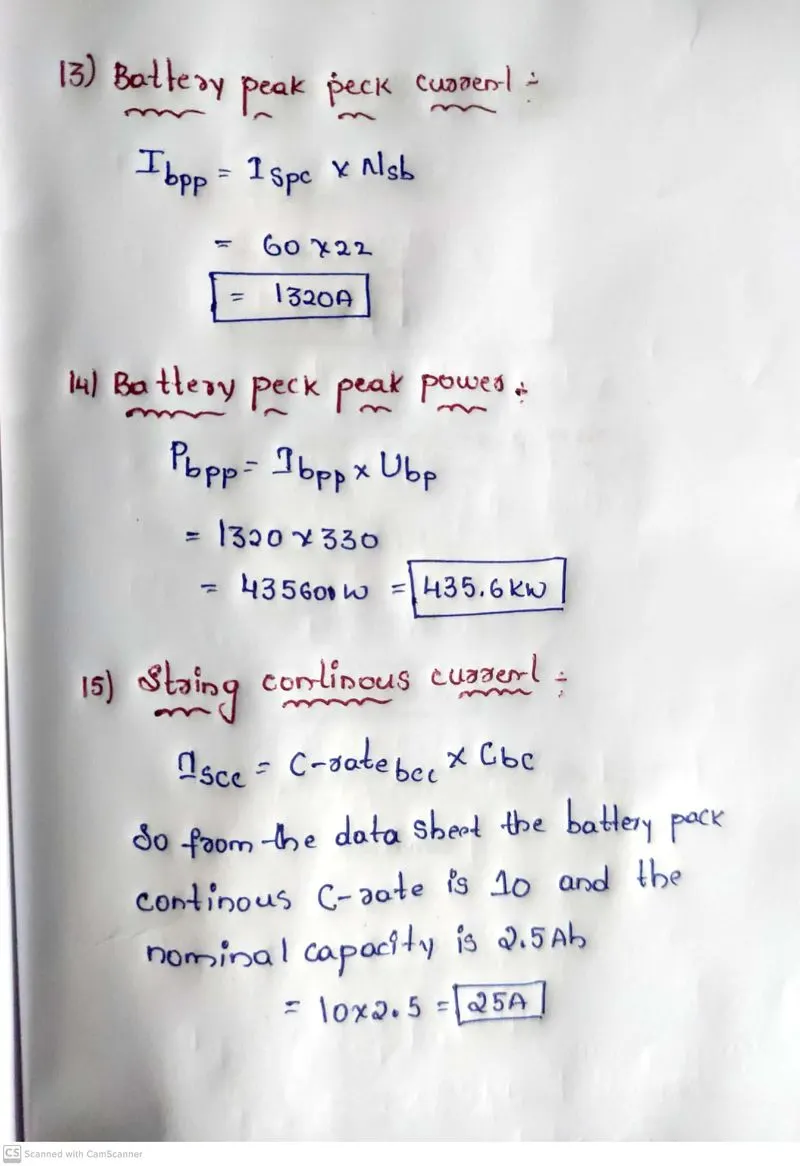
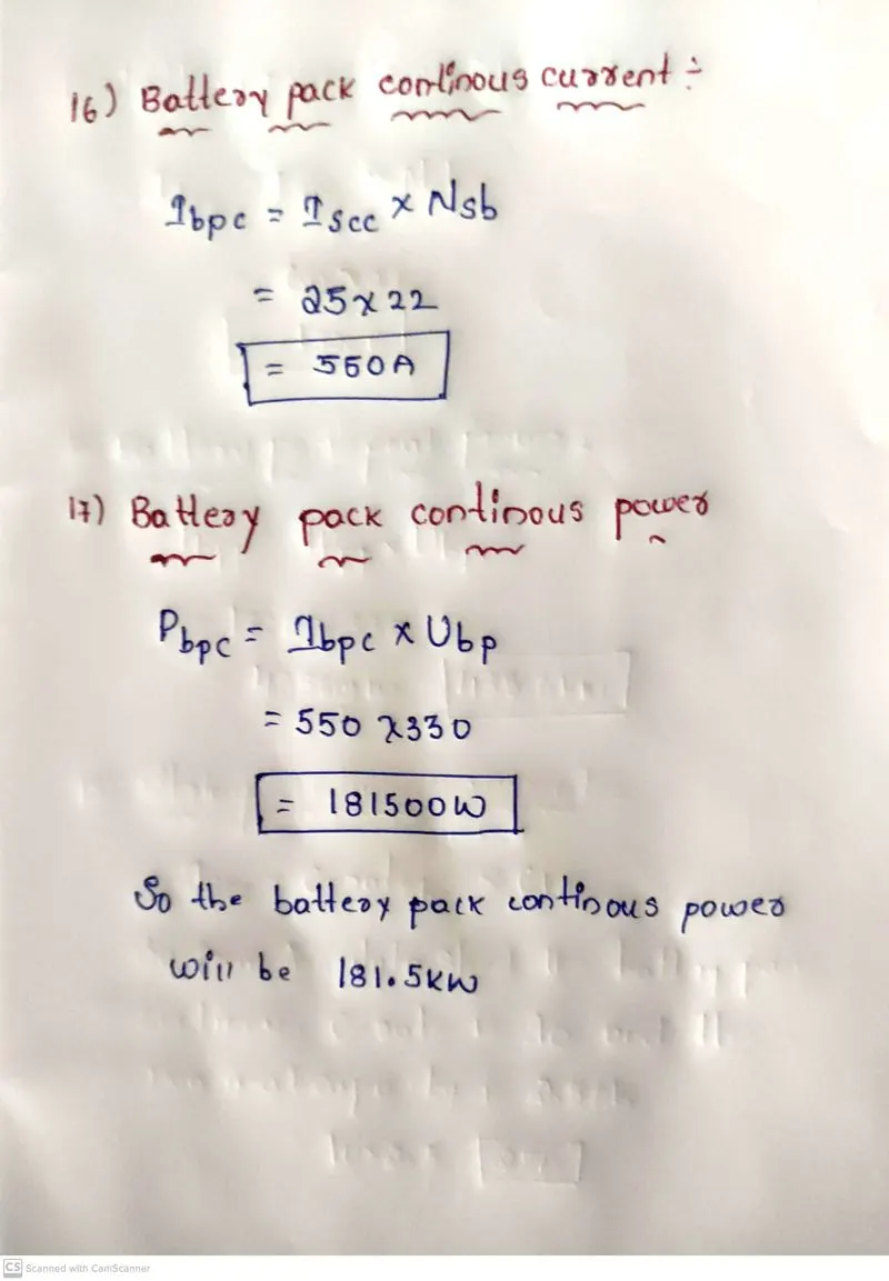
The above paramters which are calculated are shown below:
1) Manufacture: A123-systems
2)No of cells in the string: 100
3) String energy :825wh
4)No of string: 22
5) Battery pack energy: 55Ah
6) Total no of cells: 2200
7) Battery pack mass : 167.2kg
8) Battery pack volume : 0.077m^3
9) Battery pack peak current : 1320A
10) Battery pack peak power :435.6Kw
11) Battery continuous current : 550A
12) Battery pack continuous power : 181.5kw
Battery dimensions:
a)Length of the casing:
length = number of cells x (cell diameter + margin at both side of cells) + clearance at side
L = 100 x (26 + 4) + 60 = 3060 mm
b) Breadth of the casing
Breadth = number of cells x (cell diameter + margin at both side of cell) + clearance at side
B = 22 x (26 +4) + 60 = 720 mm
c)Height of the casing
Height Height of cell + margin for wiring
H = 65+35 100 mm
Now let us see the Assembly of the battery pack:
Component used for the battery pack
1. 2200 cells 2. Nickel strip
3. PVC heat sink film. 4 spot welder
5. Connected.6 Cell holder.7 Solder
Now the below steps are followed:
Step 1:
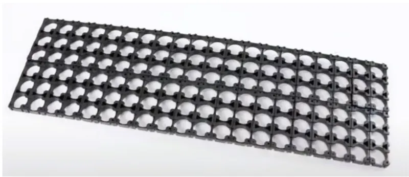
- In The first step it is to start snapping the square cell holder together.
- Which One can use the cell terminal block but they will take more space than a hexagonal block.
- This is the cell holder block
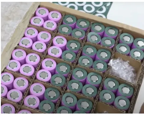
the below image shows insulate gasket

Step 2:
- The Placing the cells in the holder matrix.
- Now Place all the cells in the holder and put the second holder in the place.
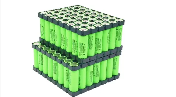
Step 3:
- Now here we will be connecting the cells with nickel strips using the spot welding process.
- Here The series connection will be made by connecting the positive terminal of the cells to the negative terminal. The parallel connection will be made by connecting the same terminal.
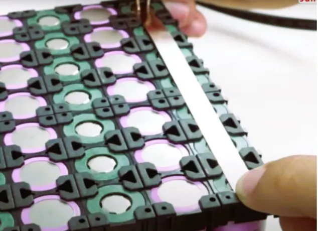
here connecting the complete matrix of the cell combined
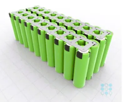
Step 4:
- Connect the heat sink to the battery pack
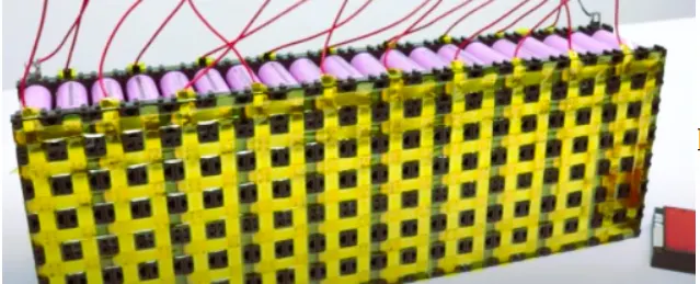
Now here we soldering the battery wire:
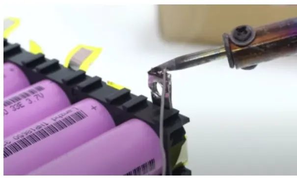
Now the internal structure of the battery pack is assembled and all the terminals are connected as per the connections:
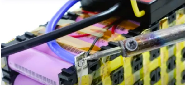
Step 5 :
Now in this step connect the balancing wire pin to the battery management system:
Step 6:
- Here After the battery management system
- So the next and final step is to place the enclosure for the battery pack.
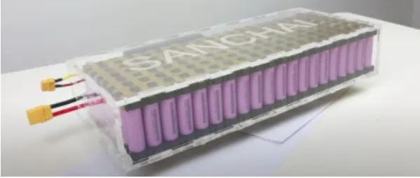
This the entire and final battery pack model created:
Conclusion:
We have desigined the battery pack and also designed the calculations and prepared a table for the same values
And aslo explained the steps involved in the making of the battery pack have been mentioned.
References:
https://datasheetspdf.com/pdf/1424845/A123Systems/ANR26650M1-B/1
https://x-engineer.org/ev-design-battery-calculation/
https://www.energy.gov/eere/articles/how-does-lithium-ion-battery-work