Project 1 Mechanical design of battery pack
Battery pack capacity: 18 kWh
Cell: ANR26650M1-B
Prepare a detailed battery pack drawing along with its enclosure. State your assumptions.
EV design – battery calculation
The high voltage battery it is one of the most important component of a battery electric vehicle (BEV). The battery parameters have a significant influence on other components and attributes of the vehicle, like:
- maximum traction motor torque
- maximum regeneration brake torque
- vehicle range
- vehicle total weight
- vehicle price
Pretty much all major aspects of a pure electric vehicle (EV) depend on the parameters of the high voltage battery.
For our electric vehicle battery design we are going to start from 4 core input parameters:
- chemistry
- voltage
- average energy consumption of the vehicle on a driving cycle
- vehicle range
A battery consists of one or more electrochemical cells (battery cells) which are converting chemical energy into electrical energy (during discharging) and electrical energy into chemical energy (during charging). The type of elements contained within a battery and the chemical reactions during discharging-charging events define the chemistry of a battery.
A battery cell consists of five major components: electrodes – anode and cathode, separators, terminals, electrolyte and a case or enclosure. For automotive applications there are different types of cells used [1]:
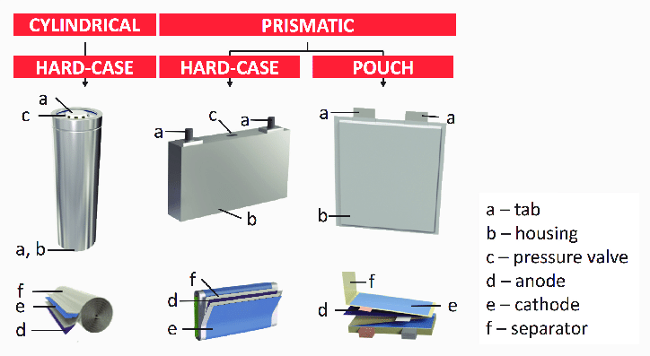
Image: Different shapes of Lithium-ion battery cells
Credit: [1]
There are several types of batteries (chemistry) used in hybrid and electric vehicle propulsion systems but we are going to consider only Lithium-ion cells. The main reason is that Li-ion batteries have higher specific energy [Wh/kg] and specific power [W/kg] compared with other types [2].

Image: Ragone diagram cell level adapted from Van Den Bossche 2009
Credit: [2]
The higher the current, the bigger the diameter of the high voltage wires and the higher the thermal losses. For this reason, the current should be limited to a maximum and the nominal power obtained by having a higher voltage. For our application we are going to consider a nominal voltage of 400 V.
In the article EV design – energy consumption we have calculated the average energy consumption for propulsion Ep as being 137.8 Wh/km on WLTC drive cycle. On top of the energy needed for propulsion, the high voltage battery must supply the energy for the vehicle’s auxiliary devices Eaux [Wh/km], like: 12 V electrical system, heating, cooling, etc. Also, we have to consider the efficiency of the powertrain ηp [-] during the conversion from electrical energy to mechanical energy.
For the auxiliary devices energy consumption we are going to use data from [3], which contains the typical power requirements of some common vehicle electrical components (auxiliary loads). The prolonged electrical loads (headlights, multimedia, etc.) and intermittent loads (heater, brake lights, wipers, etc.) use on average 430 W of electrical power. The duration of the WLTC cycle is 1800 s (0.5 h), which gives an energy of 215 Wh for the auxiliary loads. If we divide it to the length of the WLTC driving cycle (23.266 km), we get an average energy consumption for the auxiliary loads Eaux of 9.241 Wh/km.
Even if Wh/km is not really energy but factorised energy, since it’s dived per unit of distance (km), for simplicity, we are going to refer to it as average energy.
The direct current (DC) supplied by the battery is converted into alternated current (AC) by the inverter. This conversion is taking place with an associated loss. Also, the electric motor and driveline have some losses which we need to consider. For this exercise we are going to use an average efficiency ηp of 0.9 from the battery to the wheel.
Replacing the values in (2) gives the average energy consumption:
The battery pack will be designed for an average energy consumption of 161.7451 Wh/km.
Battery pack architectures
All high voltage battery packs are made up from battery cells arranged in strings and modules. A battery cell can be regarded as the smallest division of the voltage.

Image: Battery cell
Individual battery cells may be grouped in parallel and / or series as modules. Further, battery modules can be connected in parallel and / or series to create a battery pack. Depending on the battery parameters, there may be several levels of modularity.
The total battery pack voltage is determined by the number of cells in series. For example, the total (string) voltage of 6 cells connected in series will be the sum of their individual voltage.

Image: Battery cells string
In order to increase the current capability the battery capacity, more strings have to be connected in parallel. For example, 3 strings connected in parallel will triple the capacity and current capability of the battery pack.
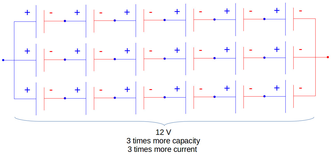
Image: Battery cell strings in parallel
The high voltage battery pack of Mitsubishi i-MiEV consists of 22 modules made up from 88 cells connected in series. Each module contains 4 prismatic cells. The voltage of each cell is 3.7 V and the total voltage of the battery pack 330 V.

Image: Battery pack (modules and cells)
Credit: Mitsubishi
Another example is the high voltage battery pack of Tesla Model S, which has:
- 74 cells in a parallel group
- 6 groups in series for a module
- 16 modules in series
- 7104 cells in total

Image: Tesla Model S battery pack
Credit: Tesla
Battery pack calculation
In order to chose what battery cells our pack will have, we’ll analyse several battery cells models available on the market. For this example we are going to focus only on Lithium-ion cells. The input parameters of the battery cells are summarised in table below.
Note: Since battery cells manufacturers come up with newer models continuously, it might be the case that the data used in this example is obsolete. This is less important since the aim or the article is to explain how the calculation is done. The same method can be applied for any other battery cells.
| Manufacturer | Panasonic | A123-Systems | Molicel | A123-Systems | Toshiba | Kokam |
| Type | cylindrical | cylindrical | cylindrical | pouch | pouch | pouch |
| Model | NCR18650B | ANR26650m1-B | ICR-18650K | 20Ah | 20Ah | SLPB7570270 |
| Source | [4] | [5] | [6] | [7] | [8] | [9] |
| Length [m] | 0.0653 | 0.065 | 0.0652 | 0 | 0 | 0 |
| Diameter [m] | 0.0185 | 0.026 | 0.0186 | 0 | 0 | 0 |
| Height [m] | 0 | 0 | 0 | 0.227 | 0.103 | 0.272 |
| Width [m] | 0 | 0 | 0 | 0.16 | 0.115 | 0.082 |
| Thickness [m] | 0 | 0 | 0 | 0.00725 | 0.022 | 0.0077 |
| Mass [kg] | 0.0485 | 0.076 | 0.05 | 0.496 | 0.51 | 0.317 |
| Capacity [Ah] | 3.2 | 2.5 | 2.6 | 19.5 | 20 | 15.6 |
| Voltage [V] | 3.6 | 3.3 | 3.7 | 3.3 | 2.3 | 3.6 |
| C-rate (cont.) | 1 | 10 | 1 | 1 | 1 | 2 |
| C-rate (peak) | 1 | 24 | 2 | 10 | 1 | 3 |
Based on the cell parameters provided by the manufacturers, we can calculate the energy content, volume, gravimetric density and volumetric density for each cell.
The volume of each cell is calculated as:
- cylindrical cells, Vcc [m3]
where:
Dbc [m] – battery cell diameter
Lbc [m] – battery cell length
- pouch cells, Vpc [m3]
where:
Hbc [m] – battery cell height
Wbc [m] – battery cell width
Tbc [m] – battery cell thickness
The battery cell energy Ebc [Wh] is calculated as:
where:
Cbc [Ah] – battery cell capacity
Ubc [V] – battery cell voltage
The battery cell energy density is calculated as:
- volumetric energy density, uV [Wh/m3]
- gravimetric energy density, uG [Wh/kg]
where:
mbc [kg] – battery cell mass
The energy density for each cells are summarised in the table below.
| Manufacturer | Panasonic | A123-Systems | Molicel | A123-Systems | Toshiba | Kokam |
| Type | cylindrical | cylindrical | cylindrical | pouch | pouch | pouch |
| Model | NCR18650B | ANR26650m1-B | ICR-18650K | 20Ah | 20Ah | SLPB7570270 |
| Energy [Wh] | 11.52 | 8.25 | 9.62 | 64.35 | 46 | 56.16 |
| Volume [l] | 0.017553 | 0.034510 | 0.017716 | 0.263320 | 0.260590 | 0.171741 |
| Energy density gravimetric [Wh/kg] |
237.53 | 108.55 | 192.40 | 129.74 | 90.20 | 177.16 |
| Energy density volumetric [Wh/l] |
656.31 | 239.06 | 543.01 | 244.38 | 176.52 | 327 |
In order to have a better overview of the cells parameters and to compare them easier, the main parameters are displayed as bar graphs in the images below.
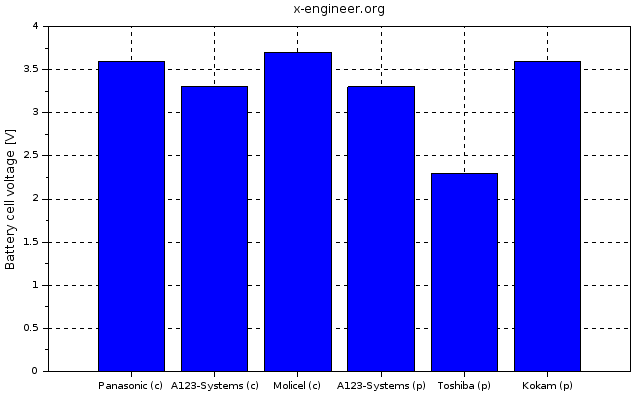
Image: Battery cell voltage |

Image: Battery cell capacity |

Image: Battery cell volumetric energy density |

Image: Battery cell gravimetric energy density |
With the above cell parameters and the core requirements for the battery (nominal voltage, average energy consumption and vehicle range), we calculate the main parameters of the high voltage battery.
The required battery pack total energy Ebp [Wh] is calculated as the product between the average energy consumption Eavg [Wh/km] and vehicle range Dv [km]. For this example we’ll design the high voltage battery pack for a vehicle range of 250 km.
The following calculations are going to be performed for each cell type. For this example we are going to consider that the battery pack is made up only from several strings connected in parallel.
The number of battery cells connected in series Ncs [-] in a string is calculated by dividing the nominal battery pack voltage Ubp [V] to the voltage of each battery cell Ubc [V]. The number of strings must be an integer. Therefore, the result of the calculation is rounded to the higher integer.
The energy content of a string Ebs [Wh] is equal with the product between the number of battery cells connected in series Ncs [-] and the energy of a battery cell Ebc [Wh].
The total number of strings of the battery pack Nsb [-] is calculated by dividing the battery pack total energy Ebp [Wh] to the energy content of a string Ebs [Wh]. The number of strings must be an integer. Therefore, the result of the calculation is rounded to the higher integer.
We can now recalculate the battery pack total energy Ebp [Wh] as the product between number of strings Nsb [-] and the energy content of each string Ebs [Wh].
The battery pack capacity Cbp [Ah] is calculated as the product between the number of strings Nsb [-] and the capacity of the battery cell Cbc [Ah].
The total number of cells of the battery pack Ncb [-] is calculated as the product between the number of strings Nsb [-] and the number of cells in a string Ncs [-].
The size and mass of the high voltage battery are very important parameter to consider when designing a battery electric vehicle (BEV). In this example we are going to caclulate the volume of the battery pack considering only the battery cells. In reality there are other factors to consider, like: electronic circuits, cooling circuit, battery casing, wiring, etc.
The battery pack mass (cells only) mbp [kg] is the product between the total number of cells Ncb [-] and the mass of each battery cell mbc [kg].
The volume of the battery pack (cells only) Vbp [m3] is the product between the total number of cells Ncb [-] and the mass of each battery cell Vcc(pc) [m3]. This volume is only used to estimate the final volume of the battery pack, since it does not take into account the auxiliary components/systems of the battery.
The volume can be also calculated function of number of strings and number of cells in a string. This calculation method is more appropriate for cylindrical cell, since the volume occupied by a cylindrical cell must take into account the air gap between cells.
The string peak current Ispc [A] is the product between the peak C-rate of the battery cell C-ratebcp [h-1] and the battery cell capacity Cbc [Ah].
The battery pack peak current Ibpp [A] is the product between the string peak current Ispc [A] and the number of strings of the battery pack Nsb [-].
The battery pack peak power Pbpp [W] is the product between battery pack peak current Ibpp [A] and the battery pack voltage Ubp [V].
The string continuous current Iscc [A] is the product between the continuous C-rate of the battery cell C-ratebcc [h-1] and the battery cell capacity Cbc [Ah].
The battery pack continuous current Ibpc [A] is the product between the string continuous current Iscc [A] and the number of strings of the battery pack Nsb [-].
The battery pack continuous power Pbpc [W] is the product between battery pack continuous current Ibpc [A] and the battery pack voltage Ubp [V].
The results of the equations (7) to (20) are summarised in the table below.
| Manufacturer | Panasonic | A123-Systems | Molicel | A123-Systems | Toshiba | Kokam |
| # of cells in string [-] | 112 | 122 | 109 | 122 | 174 | 112 |
| String energy [Wh] | 1290 | 1007 | 1049 | 7851 | 8004 | 6290 |
| # of strings [-] | 32 | 41 | 39 | 6 | 6 | 7 |
| BP energy [kWh] | 41.29 | 41.27 | 40.89 | 47.10 | 48.02 | 44.03 |
| BP capacity [Ah] | 102.4 | 102.5 | 101.4 | 117 | 120 | 109.2 |
| # total cells [-] | 3584 | 5002 | 4251 | 732 | 1044 | 784 |
| BP mass [kg]* | 173.8 | 380.2 | 212.6 | 363.1 | 532.4 | 248.5 |
| BP volume [l]* | 63 | 173 | 75 | 193 | 272 | 135 |
| BP peak current [A] | 102.4 | 2460 | 202.8 | 1170 | 120 | 327.6 |
| BP peak power [kW] | 40.96 | 984 | 81.12 | 468 | 48 | 131.04 |
| BP continuous current [A] | 102.4 | 1025 | 101.4 | 117 | 120 | 218.4 |
| BP continuous power [kW] | 40.96 | 410 | 40.56 | 46.8 | 48 | 87.36 |
BP – battery pack
* – taking into account only battery cells
From the table data we can see that the pouch type cell have better energy content and higher capacity compared with the cylindrical cells.
The same results can be plotted in bar graphs for an easier comparison between the different types of battery cells.

Image: Battery pack energy |

Image: Battery pack capacity |

Image: Battery pack total number of cells |
|

Image: Battery pack mass (cells only) |

Image: Battery pack volume (cells only) |
Because of the low capacity for the cylindrical cells, compared to the pouch cells, the number of cells required for the battery pack is significant higher. A high number of cells might cause additional problems in areas of wiring, voltage monitoring, battery reliability.
The mass and volume are calculated only at cell level, taking into account the cell dimensions and mass. The battery pack which will be in the vehicle will have additional components (wires, electronic components, soldering, case, etc.), which will increase both the final volume and mass. Nevertheless by looking only at cell based volume and mass, we can estimate which model will be better compared to the other. In terms of mass and volume there is no clear distinction between cylindrical and pouch cells. However it seems that a battery pack with pouch cells is slightly heavier and bigger.
The battery cells manufactured by A123-Systems have very high maximum continuous discharge current and maximum pulse (peak) discharge current. As for energy and capacity, the pouch type cells have higher peak (continuous) current and power than cylindrical cells.
Based on the calculated data and conclusions, we can choose which battery cells are suitable for our electric vehicle battery pack. From our examples it looks like Kokam cells have the best compromise between mass, volume and energy/power density.
Cell: ANR26650M1-B Data Sheet:
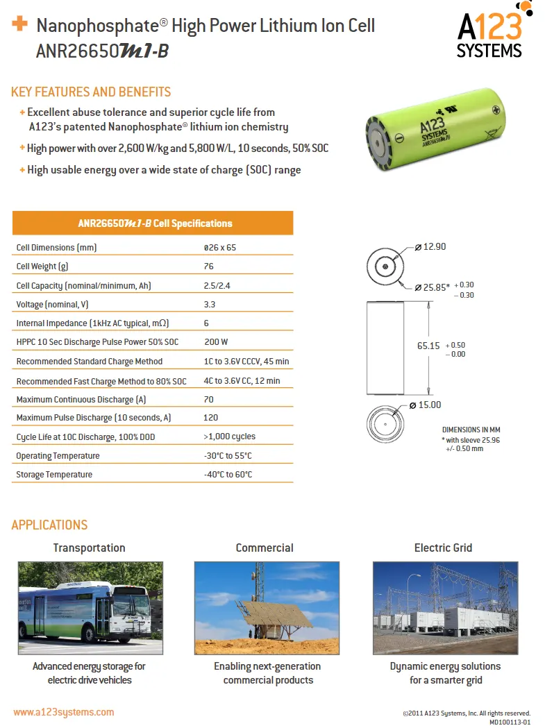
Cell calculations:
Battery pack calculation
we calculation of battery we connect battery are connected in series and parallel combination cells are connected for the to required the output of 18kw there for the we assumed the 52 cells in series and 42 cells in parallel.
1. total number of cells required
total number of cells= No of celles in series * No of celles in parallel
=52*42
=2100 no's
2. voltage and current calculation of required the output of 18kw for that
a. voltage = no of celles in series * battery nominal voltage
= 52*3.3
=171.6V
total voltage of celles=171.6v
b. current = no of celles in parallel * battery nominal current (capacity)
= 42*2.4
=105.0Ah
total current of celles=105Ah
c. total output of the connection form series parallel combination of celles afret connection how much we get output
power =voltage* current
=171.6*105
=18018w
=18.018kAh
3. volume of cells: the volume of the cells are the calculation by using for of cylender the ANR26650M1-B cylendical in nature that why using.
a. each celles volume of celles=`πr^2h`
=3.14*12.925^2*65.15
=34192.07MM
b. the calculation of total volume of the battery pack.
total volume of the battery pack= volume of each cells* No of celles connections.
=34192.07*2100
=71803347MM
Total volume of battery pack is 71803347MM or 0.0718033m^3
c. the total weight of the barrery pack
total weight of battery pack= No of cells* each cells standerd weight
=2100*76
=159600g
=159.600kg
total weigth of battery pack= 159.6kg
d. energy dencity= volume * battery pack output
=0.0718033*18018
= 1293.75186 kwh/m^3
Prepare a detailed battery pack drawing along with its enclosure. State your assumptions.
Battery Pack Assembly . The design of the outer package or housing of the battery depends to a great extent on the components it has to accommodate and the physical protection it has to provide for them . These components are not just the cells , but also protection devices , electronic circuits , interconnections and connectors which must all be specified before the final battery case can be designed . For high power , high energy batteries robust packaging is required for safety reasons .
Cell holder dimensions
Height - 12mm
length = 30mm
width = 30mm
weight = 5gm
Arrangement of cells in 52542P together is not the best arrangement as it will take
30mm 52 cells -1560mm For 52 cells in series
30mm 42 cells - 1260mm For 36 cells in parallel so , a total of ( 1560-1260 ) space required and all the cells in a single matrix will lead to poor thermal management as we are employing the air cooled technique in the battry pack the ventilators will not be able to cool the inner cells as the air will not reach till the inner cells Also , according to the 18KWh capacity , the application might be in a small 2 seater Electric car the area taken by the battery pack assembly is 1.56 *1.26 meters The solution for both the space required and the thermal management of battery pack is to create a module of . Arranging such 8S5P and 1S1P modules in 6S7P manner will create a 52S42P array giving 171.1V 105Ah .
While most people know what components comprise a traditional gasoline-powered automobile engine, they likely know little about the components or parts of an Electric Vehicle (EV) battery pack. This is understandable because EVs are still relatively new in the automotive marketplace, and the conception of how exactly a battery works is more difficult to understand when compared with the myriad of moving components that comprise internal combustion engines.
In reality, EV battery packs possess many traditional machine components. EV battery pack manufacturing processes, in particular, rely heavily on a variety of machine components including MISUMI components which are present at every step in the fabrication process.
To grasp this process, it’s helpful to unpack some basic terminology first. The Battery Cell is a small, rectangular component roughly the geometry of a paperback book. These battery cells are assembled together in frames to form Battery Modules. These modules are then linked together via a myriad of electrical connections and enclosed in the Battery Pack which is assembled directly to the automobile frame. The following arrow diagram below is a compass to understand the process terminology.
Battery Cells -> Battery Modules -> Battery Pack

Battery Cells

Battery Modules

Battery Pack
The process outlined in this article will begin with taking the battery cells out of packaging. This article will discuss the fabrication process using the battery cells as the “raw material” in the battery pack fabrication process. These small individual cells are typically manufactured at other, specialized facilities and arrive at the automobile fabrication plant as completed products. This workflow is the vision for the vaulted Tesla Gigafactory in Nevada which will produce all the battery cells required for the Tesla’s automotive assembly facilities.
The individual battery cells are simply metallic cartridges that contain an anode, cathode, and separator immersed in an electrolyte fluid.

Lithium-Ion Battery Schematic
Before the cells can be assembled into modules, each cell undergoes checks within a specialized fixture. This process is essentially a “leak check” process to ensure that the electrolyte isn’t leaking from the cell and to ensure that no moisture intrusion occurs over the entire operational life of the battery. This step is vitally important to ensure that the cells are properly functioning, and future battery capacity won’t be compromised.

EV Battery Assembly Fixture
The machine components that unpack the battery cells from packaging are comprised of many components such as power cables, roller conveyors, rotary shafts, and linear ball bushings.
The fixtures that check the battery cells are also comprised of dozens of components such as aluminum extrusions, configurable mounting plates, timing belt/pulley systems, circular cordsets, and circular co
The next step in the process involves assembling the battery cells into battery modules. Typically, there are about 12 battery cells per battery module, but this varies across automotive make and model. The modules stack within a metallic frame. This frame comprises the module housing and protects the cells from physical shock loads.
This assembly process is highly automated and involves many MISUMI configurable machine components. The most visible of these components are the timing and conveyor belts which run the workpieces through the process.

The last step in battery pack fabrication is assembling the modules into the battery pack housing. This step involves a significant number of electrical hookups and fine-tuning. For example, the Nissan Leaf EV contains 48 battery modules which are all connected together via electrical monitoring equipment. These modules are typically picked and placed by an automated robotic assembly arm into the battery pack housing. After all the modules are placed into the housing they are manually connected together by an automotive technician. After all connections have been made, the battery pack housing cover is placed manually; finally, an automated robot arm is typically used to drill all screws thus completing the battery pack fabrication process.


the above fig show the cell holder for holding the number of celles
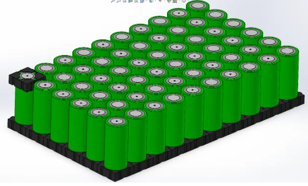
the arragement of celles in cell holder
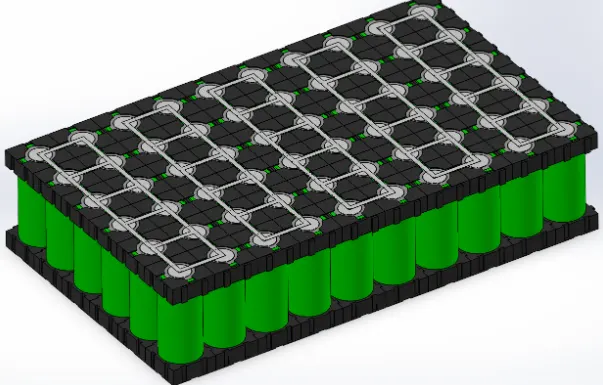
Step Add cell holders on the upper side of cells and also odd nickel stripe for series and paralel connections Now one module is complete 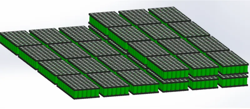
The above fig shows the image shows the arrangement of such modules this completes the battery pack by with the required combination of cells .
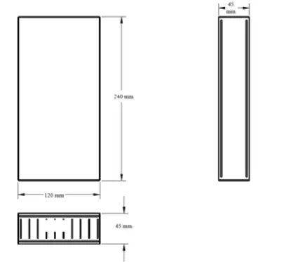
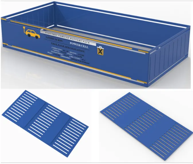
The above fig shows the battery pack encloser shown
Remarks:
for this calculation i was consider celles connection and also having other method also that can be battery voltage can assumed.