Project 1 Mechanical design of battery pack
Mechanical design of battery pack
The prospect of rapid global temperature increase has created the need for a reduction in the use of fossil fuels and the associated emissions. India has committed to cutting its GHG emissions intensity by 33% to 35% percent below 2005 levels by 2030. India needs a minimum of 10 GWh of cells by 2022, which would need to be expanded to about 50 GWh by 2025. Therefore, manufacturing these cells in India would be encouraged.
Design or selection of battery pack for particular vehicle application must have the following consideration
- Optimization of power and torque.
- Vehicle range
- Battery pack life.
- Safety
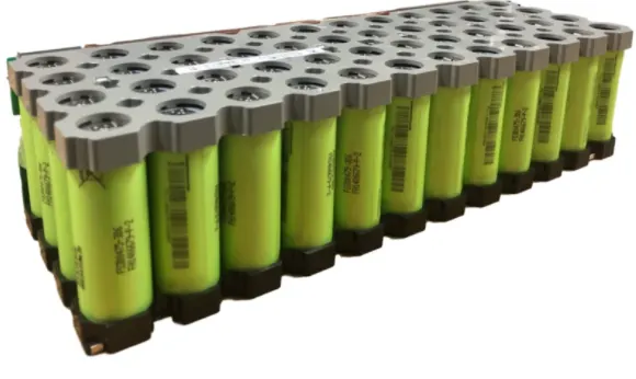
Cells are connected in series or parallel in battery pack. While, series connection compound the voltage and this determine the power of the vehicle, on the other hand parallel connection determine the capacity and thus range of the vehicle. Thus, design of battery pack starts with cell chemical composition, number of cell connected in series and in parallel.
Mechanical design of battery pack essentially has thermal and structural boundary, thus, Structural rigidity, impact resistance, vibration control, thermal stability etc are the primary considerations. During design following parameter should be taken into consideration. Customer usage, vibration, ambient temperature, cell to cell variation, auxiliary load. Also, following optimization to be done during design. Lightweight, compact packing, structural rigidity, swappable / serviceability, ease of manufacturing, cost optimization etc.
The total number cell to be connected in series and in parallel can be determined from the tractive effort of the vehicle. The total tractive effort is the summation of rolling resistance, aerodynamic drag, hill climbing force, force required for linear acceleration, force required to give angular acceleration to the rotating motor.
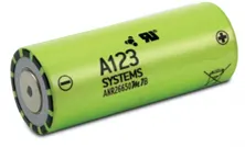
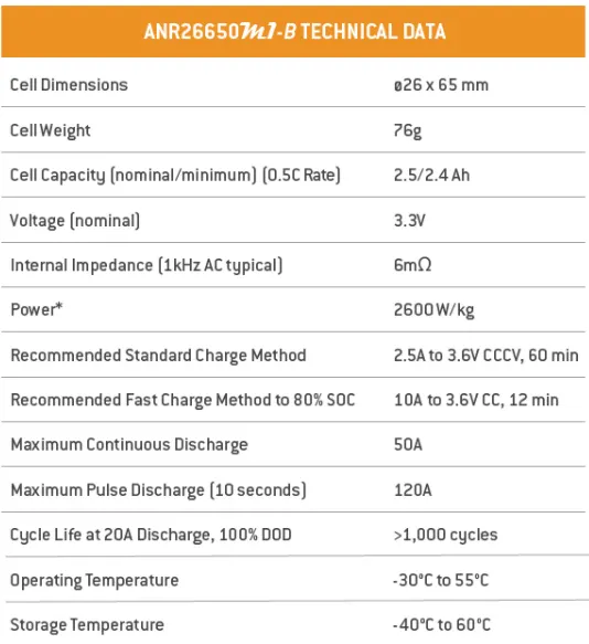
Calculation is shown below to provide basic idea for certain speed and range of vehicle. Only rolling resistance and drag force is considered in this calculation. This is to determine the number of cells in series and in parallel. ANR26650M1-B cell is used to design the battery pack.
|
Parameter |
unit |
|
|
Max Vehicle speed |
kmph |
100 |
|
Vehicle range |
km |
150 |
|
Vehicle mass |
kg |
1000 |
|
Passenger average mass |
kg |
70 |
|
No of passenger |
4 |
|
|
Co-efficient of rolling resistance |
0.015 |
|
|
Rolling Force |
N |
188.352 |
|
Drag coefficient |
0.25 |
|
|
Fluid density |
kg/m3 |
1.2 |
|
Frontal area |
m2 |
2.2 |
|
Cell parameter |
||
|
Cell voltage |
V |
3.3 |
|
Cell Capacity |
amp hr |
2.4 |
|
Cell diameter |
mm |
26 |
|
cell height |
mm |
65 |
|
Cell weight |
gm |
76 |
|
Motor Voltage required |
V |
151.8 |
|
Max Vehicle speed |
m/s |
27.78 |
|
Vehicle total mass |
kg |
1280 |
|
Drag force |
N |
254.63 |
|
Net force |
N |
442.98 |
|
Power usage |
kW |
12.31 |
|
Energy usage |
kWh |
18.46 |
|
Battery Pack Capacity |
amp hr |
121.59 |
|
No of cell in series |
46.00 |
|
|
No of cell in series |
46 |
|
|
No of cell in parallel |
50.66 |
|
|
No of cell in parallel |
51 |
|
|
Total no of cell required |
2346 |
|
|
Battery pack corrected energy |
kWh |
18.58 |
|
Cell volume |
m3 |
3.45104E-05 |
|
Volume of battery pack (Cell only) |
m3 |
0.080961387 |
|
Weight of bettery pack (Cell Only) |
kg |
178.296 |
From the above calculation, number of cells in series and in parallel connection is determined. From this, the cell only weight & volume of the battery pack can be determined. Total volume of the battery pack can be determined after electrical connection and colling/heating requirement.
Battery Interconnect System:
Battery interconnect system are the metal strip or connectors to interconnect the cell. Spot weld / laser weld / wire bond are used to interconnect the cells. The challenges of interconnection are as below:
- Electrical and Thermal challenges: Interconnection should be such that it a) will produce joints with low electrical resistance, b) will produce joints with low thermal input and c) should have high thermal fatigue resistance.
- Metallurgical challenges: a) Comparability of dissimilar material joint b) Variability of material and surface
- Mechanical Challenges: a) Durability b) Mechanical and vibration damage of joint.
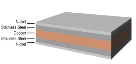
Usually copper strip / Nickel strip is generally used to interconnect the cells. The disadvantage of nickel strip is the heat generation issue. SIGMAclad is the solution to the heat generation. This consist of layer of Nickel , Stainless steel and coper. This provides, superior conductivity, High power capacity, light weight and robust weld. Nickel on the surface provides the high contact corrosion protection, stainless steel provides robust weld. Below is the image of SIGMAclad.
Below is the system diagram of parallel buck regulated battery modules. In each module, the battery is represented by a series connection of battery cells to create the desired OCV.
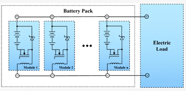
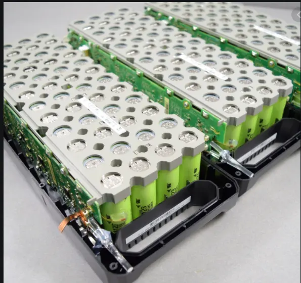
Sample model of battery module and pack is shown below.