Project 1 Mechanical design of battery pack
Battery pack capacity: 18 kWh
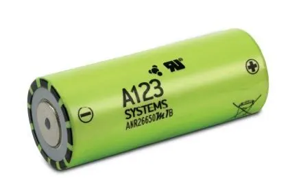
Cell: ANR26650M1-B
detailed battery pack drawing along with its enclosure:
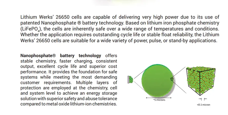
ANR26650M1-B Specifications
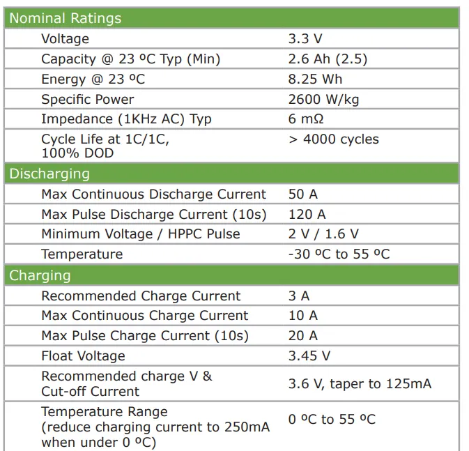
Nominal Ratings
Voltage: 3.3 Volts
Capacity: 2.5 Ah
Energy: 8.25 Wh
Specific Power: 2600 W/kg
Impedance (1KHz AC Typical) 6 mΩ
Cycle Life at 1C/1C, 100% DOD: > 4000 cycles
Cell Type: 26650 Lithium Ion Power Cylindrical Cell
Discharging
Max Continuous Discharage: 50 A
Max Pulse Discharge Current >50% SOC (10s): 120 A
Minimum Voltage: 2 Volts
Temperature: -30ºC to 55ºC
Charging
Recommended Standard Charge: 2.5 Amps
Max Charge Rate: 10 Amps
Max Pulse Charge Current <50% SOC (10s): 25 A
Float Voltage: 3.45 Volts
Recommended charge V & Cut-off Current: 3.6 Volts, taper to 125mA
Temperature
(reduce charging current to 250mA when under 0ºC): 0ºC to 55ºC
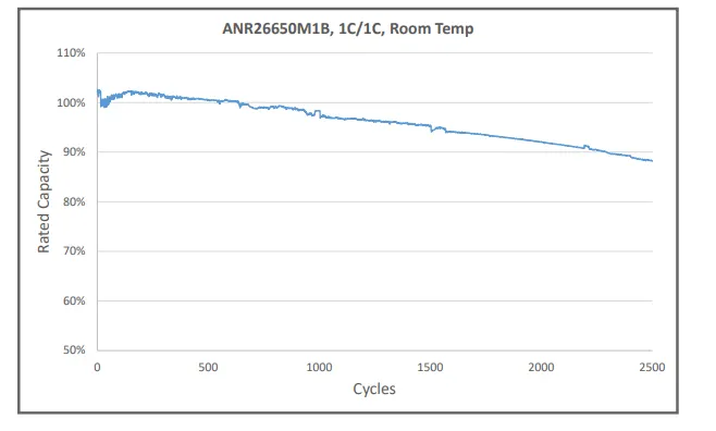
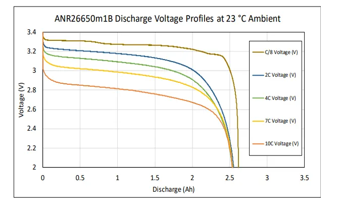
we assume total volatge 500V and nominal voltage of one cell is3.3V then
no. of cells required in series=total voltage/nominal voltage
===>500v/3.3v=151.51
===>=152-no.of cells required in series
no. of cells in parallel=total current/nominal capacity
===>10amp/2.5ah=4
cell architecture==152S 4P
total no.of cells = no.of cells in series*no.of cells in parallel
===>152*4=608
battery capacity=parallel cell in row*individual cell capacity
===>4*2.5
==>10
Range=capacity/energy consumption
we assume powertrain energy consumption is 100wh/km at 70% then
===>18000/100
===>180km
Battery dimensions:
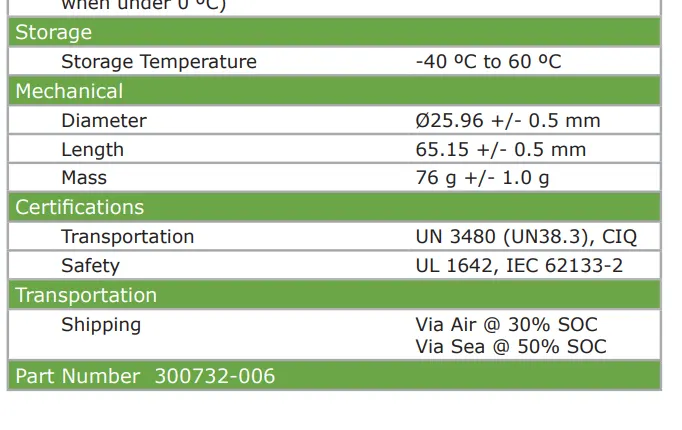
Diameter: Ø25.96 +/- 0.5 mm (1.0")
Length: 65.15 +/- 0.5 mm (2.6")
Mass: 76g
Battery cell:
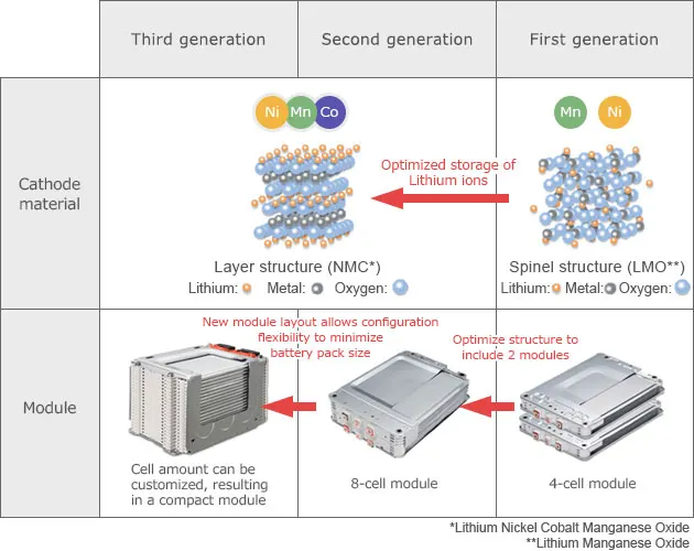
We have already provided some basics about Li-ion cells in our previous blog posts, including different form factors and chemistry types. At the base of every Li-ion battery pack is the battery cell or cells. A pack can contain one cell or many cells configured to achieve higher capacity or output voltage. This is achieved by connecting cells in parallel or series, and we'll explore this much further in our next blog. The cell is considered the “fuel tank” of the battery pack system, holding the energy that will be released during discharge or replaced during a charge cycle . However, there are other components needed to utilize the energy stored in the cell.
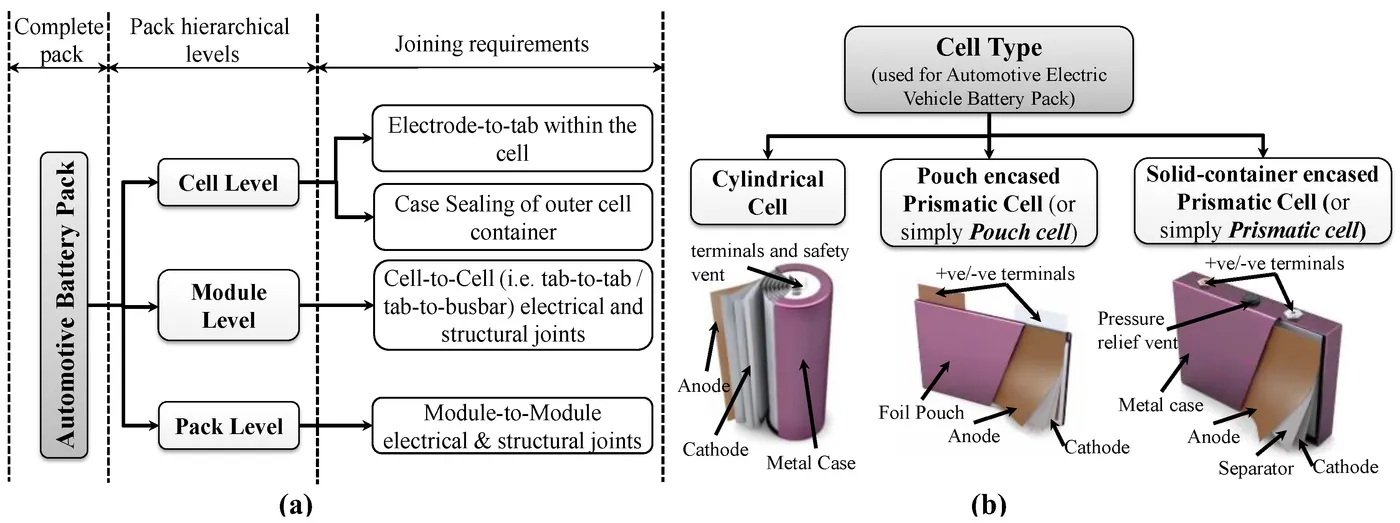
cell module and array:A cell is defined as the semiconductor device that converts sunlight into electricity. A PV module refers to a number of cells connected in series and in a PV array, modules are connected in series and in parallel. The modification presented in this paper accounts for both parallel and series connections in an array.
BMS
To safely use the energy stored in cells, the Li-ion battery pack needs a Battery Management System (BMS) .The BMS is the control system of the pack and can be simple or complex, depending on the need of the battery pack and host application. Returning to the car analogy, think of a battery pack's BMS like a car's control system. In a car, the control system shuttles fuel from the fuel tank to the engine to be utilized in a controlled and safe manner and notifies the user of any issues . The BMS performs a similar role by safely regulating the energy carried through the cells inside a battery pack. It can also communicate information back to the end user
Connection System
While we may understand the basic concept of a cell and the BMS, how do these components interact with one another? The connection system is what transforms a cell into a battery pack. There must be a connection between the cell and the BMS in order to interface with each other. Nickel strips are the preferred method of connecting a battery cell to the control system. A thin strip of nickel is capable of carrying high amounts of current, is flexible, durable, and can be attached to the cell without the use of excessive heat. These strips provide a safe means of getting the "fuel" out of the "fuel tank" to use it in a safe manner.
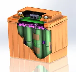
Resistance spot, ultrasonic or laser beam welding are mostly used for connecting battery cells in the production of large battery assemblies. Each of these welding techniques has its own characteristicsdepending on the material properties and contact geometry. Cell casing and terminal dimensions may constrain possible contact geometries. For example, pouch cells provide detached tabs, whereas cells with hard casing provide a certain area of the casing for electrical connection. Consequently, it is a challenging task to find the most suitable welding technique and welding parameters for each individual battery assembly.
Ultrasonic metal welding or UMW, is a solid-state welding technique which forms a bond by applying moderate static pressure and an ultrasonic oscillation of about 20 kHz between twoparts of metal. The solid-state weld is formed through the high frequency motion between the parts causing continuous shearing and plastic deformation while alsoremoving any oxide layers or contaminants. The complete bonding mechanism is not fully understood, but some combination of metal interlocking,micro melting as well as metallic andchemical bonding is believed to aid in the creation of the bond. Most metals can be ultrasonicallywelded and the method is excellent for welding together thin foils, as well as thicker sheets with spot or seam welds and also wires
Battery holder:
A battery holder or a battery mount is an integrated or separate cavity to hold cells. If it is a separate compartment, it can be attached to a cell-powered device. It is used to hold the cells securely and power the device it is attached to The primary function of a battery holder is to keep cells fixed in place safely and securely while conveying power from the batteries to the device in question. External connections on battery holders are most often made by contacts either with pins, surface mount feet, soldered lugs or via a set of wire leads External connections on battery holders are usually made by contacts with pins, surface mount feet, solder lugs, or wire leads. Where the battery is expected to last over the life of the product, no holder is necessary, and a tab welded to the battery terminals can be directly soldered to a printed circuit board.