Project 1 Mechanical design of battery pack
Objective:
The main objective of this challenge is to understand the mechanical design of a battery pack, and the mathemtical calculations required to design a battery pack mechanically.
The market of electric vehicle domain increasing day by day, with respect to the ev domain the lithium-ion cell growth is also increased. The lithium-ion cells many advantages compared to lead-acid batteries some of them are listed below,
- Inherently safe chemistry. BMS provides extra protection.
- No damage from partial state of charge operation or storage.
- Full power available throughout discharge. Voltage does not drop like lead-acid batteries.
- Low self discharge so the battery m,aintains state of charg.
- 50-60% less weight than lead-acid batteries
- 2.5X more efficient at low temperatures. Safely operational upto `149^oF (65^oC)`.
- Plug, play and charge. No watering.
- upto 10X longer cycle life than lead-acid equivalent.
- Hightly efficient charging. Can fully charge in 1-3 hours, built-in overcharging protection.
Lithium-ion cells are used in aerospace, automotive electric vehicle, mobile devices, medical devices and other electronic devices which is based on these cells. The battery pack is installed in lower-floor of the electric vehicle so that weight may distribute equally and also the centre of gravity also maintain properly.
The high voltage battery pack is one of the most important components of any electric vehicle. The traction battery of an electric vehicle must achieve the following,
- Provide maximum traction motor torque.
- Vehicle range in sense of kilometre.
- To achieve the proper life cycle of battery.
Battery:
A battery is the generic name for a unit that creates electrical energy from stored chemical energy. Strictly it consists of two or more cells connected in an appropriate series / parallel arrangement to provide the required operating voltage and capacity to meet its operating requirements. The term battery is also frequently used to refer to a unit consisting of a single cell, especially when it contains battery management circuitry.
Battery pack:
A battery pack is a set of any number of (preferably) identical batteries or individual battery cells. They may be configured in a series, parallel or a mixture of both to deliver the desired voltage, capacity, or power density. The term battery pack is often used in reference to cordless tools, radio-controlled hobby toys, and battery electric vehicles. Components of battery packs include the individual batteries or cells, and the interconnects which provide electrical conductivity between them. Rechargeable battery packs often contain a temperature sensor, which the battery charger uses to detect the end of charging. Interconnects are also found in batteries as they are the part which connects each cell, though batteries are most often only arranged in series strings.
When a pack contains groups of cells in parallel there are differing wiring configurations which take into consideration the electrical balance of the circuit. battery regulators are sometimes used to keep the voltage of each individual cell below its maximum value during charging so as to allow the weaker batteries to become fully charged, bringing the whole pack back into balance. Active balancing can also be performed by battery balancer devices which can shuttle energy from strong cells to weaker ones in real time for better balance. A well-balanced pack lasts longer and delivers better performance. For an inline package, cells are selected and stacked with solder in between them. The cells are pressed together and a current pulse generates heat to solder them together and to weld all connections internal to the cell.
Stages of battery pack is,
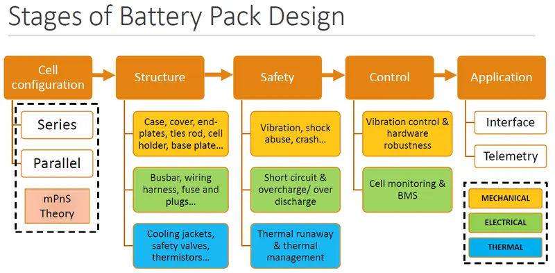
The steps to make a battery pack is,
Considerations to design a battery pack:
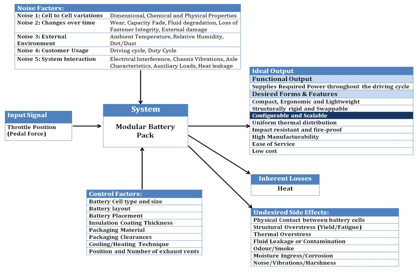
Mechanical Design of A Battery Pack:
Safety and reliability are the major concerns for the large battery packs. While we designing the battery pack mechanically we should the technical criteria to overshoot from the battery failures,
- Mechanical vibration should decrease
- Controlling on high impact force
- Better thermal runway for cooling
- Serviceability and recyclability
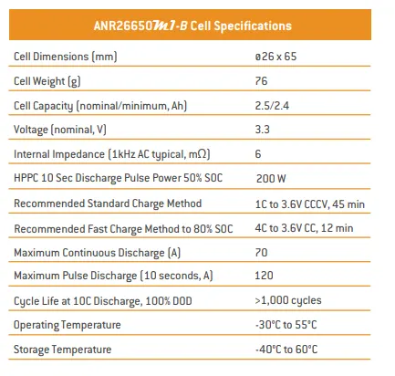
To design 18kW battery pack the below given cells are used. The cell specification and chemistery are given below,
- The battery pack capacity: 18 kWh
- cell: ANR 26650M1-B
Datasheet: https://www.batteryspace.com/prod-specs/6610.pdf
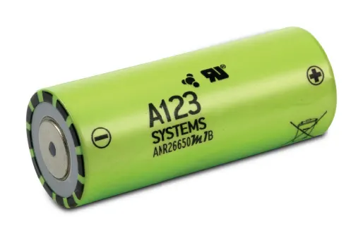
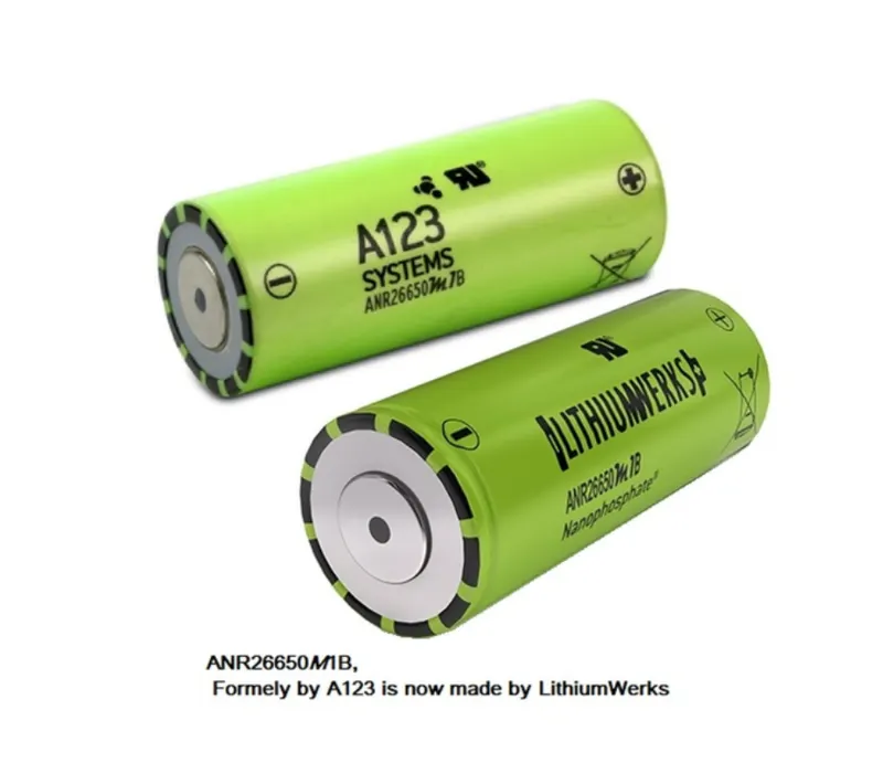
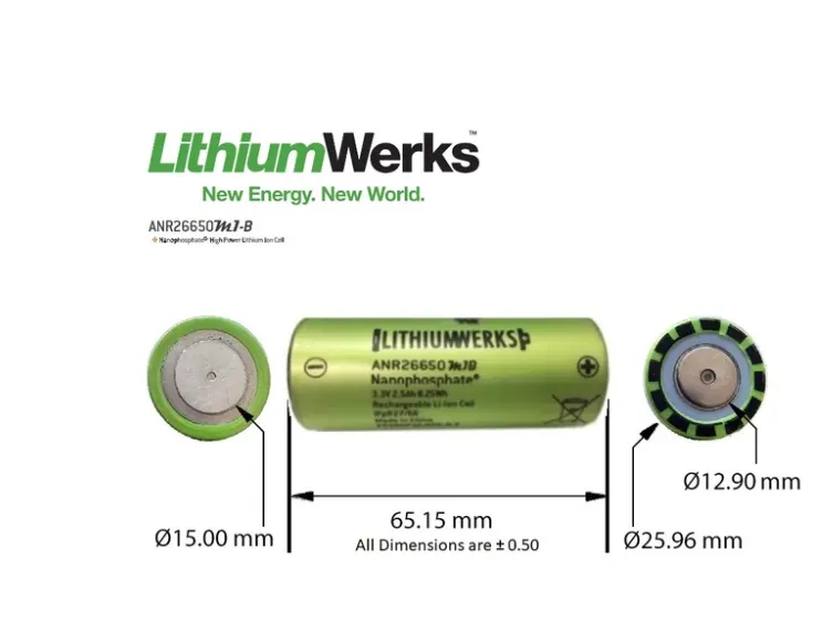
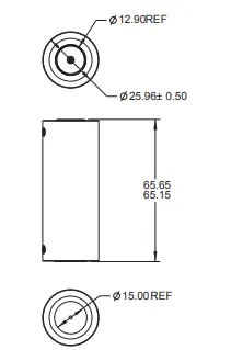
A123 Systems’ high-performance Nanophosphate lithium-ion technology delivers high power and energy density combined with excellent safety performance and extensive life cycling.
A123 Systems’ Nanophosphate lithium-ion products have low capacity loss and impedance growth over time, allowing systems to meet end-of-life power and energy requirements with minimal pack oversizing. Mid-Continent Instruments and Avionics is proud to be the exclusive worldwide distributor of A123’s Nanophosphate lithium-ion cells for the aviation industry. The technology provides significant weight savings and cost of ownership advantages over legacy lead-acid designs.
Safety begins with chemistry. A123 Systems’ Nanophosphate® is stable chemically, which provides the foundation for safe systems while meeting the most demanding customer requirements. Multiple layers of protection are employed at the chemistry, cell and system level to achieve an energy storage solution with superior safety and abuse tolerance.
A123’s high-performance Nanophosphate lithium iron phosphate (LiFePO4) battery technology delivers high power and energy density combined with excellent safety performance and extensive life cycling in a lighter weight, more compact package. Our cells have low capacity loss and impedance growth over time as well as high usable energy over a wide state of charge (SOC) range, allowing our systems to meet end-of-life power and energy requirements with minimal pack oversizing.The cell may achive following features,
- Stable chemistry.
- Faster charging.
- Consistent output.
- Excellent cycle life.
- Superior cost performance.
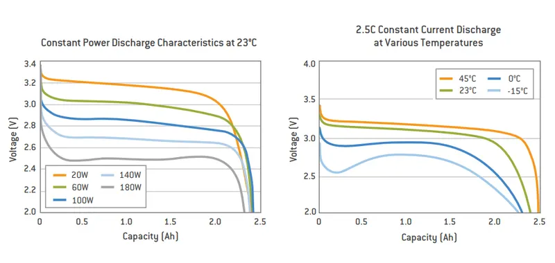
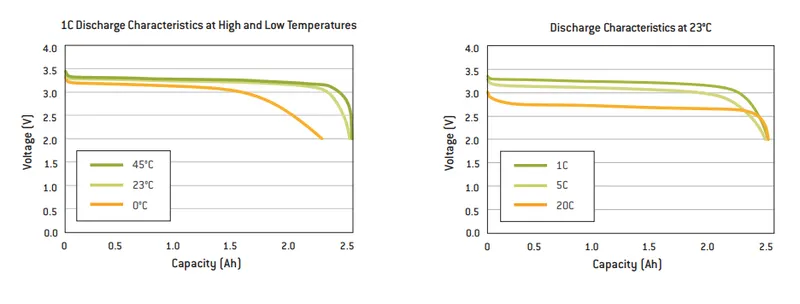
The below given plot is for constant power discharge characteristics at `23^oC` and another one is also a constant current discharge at various temperatures at `2.5C`,
The below given plot is for '1C discharge characteristics at high and low temperatures and another one is discharge characteristics at`23^oC`',
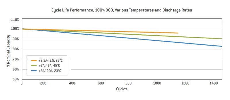
The below given plot visualizes the cucle performance, 100% DOD (depth of discharge) and various temperatures & discharge rates,
Battery Terminology:
- Capacity: The capacity of a battery or cell is defined as the amount of energy that it can deliver in a single discharge. Battery capacity is normally specified in amp-hours for larger batteries and mill-amp-hours for smaller batteries. The capacity may be quoted on the battery itself and also in the specification. Many rechargeable cells and batteries have the charge capacity stated on the outer casing, whereas it is normally necessary to look int he manufacturers specifications for non-rechargeables.
- Charge Capacity: The capacity of a battery is often referred to as the charge capacity as this is the amount of charge the battery can hold. See "Capacity."
- Charge Rate (C-rate): The definition of the charge rate or C-rate of a battery or cell is the charge or discharge current in Amperes as a proportion of the rated capacity in Ah. For example, in the case of a 500 mAh battery, a C/2 rate is 250 mA and a 2C rate would be 1 A.
- Constant-Current Charge: This refers to a charging process where the level of current is maintained at a constant level regardless of the voltage of the battery or cell.
- Constant-Voltage Charge: This definition refers to a charging process in which the voltage applied to a battery is held at a constant value over the charge cycle regardless of the current drawn.
- Cycle Life: The capacity of a rechargeable cell or battery changes over its life. The definition of the battery life or cycle life of a battery is number of cycles that a cell or battery can be charged and discharged under specific conditions, before the available capacity falls to a specific performance criteria - normally 80% of the rated capacity. The cycle life of batteries is gaining even more in importance. Mobile phones are often replaced when their batteries come to the end of their life, and for electric cars the battery life time is of great importance as replacement of the batteries is a very expensive operation.
- Cut-off Voltage: As a battery or cell is discharged it has a voltage curve that it follows - the voltage generally falling over the discharge cycle. The definition for a cell or battery of the cut-off voltage cell or battery is the voltage at which the discharge is terminated by any battery management system. This point may also be referred to as the End-of-Discharge voltage.
- Deep cycle: A charge discharge cycle in which the discharge is continued until the battery is fully discharged. This is normally take to be the point at which it reaches its cut-off voltage, typically 80% of discharge.
- Energy Density: The volumetric energy storage density of a battery, expressed in Watt-hours per litre (Wh/l).
- Power Density: The volumetric power density of a battery, expressed in Watts per litre (W/l).
- Self-Discharge: It is found that batteries and cells will lose their charge over a period of time, and need re-charging. This self-discharge is normal, but various according to a number of variables including the technology used and the conditions. Self-discharge is defined as the recoverable loss of capacity of a cell or battery. The figure is normally expressed in a percentage of the rated capacity lost per month and at a given temperature. The self-discharge rate of a battery or cell is very dependent upon the temperature.
- Specific Energy: The gravimetric energy storage density of a battery, expressed in Watt-hours per kilogram (Wh/kg).
- Specific Power: The specific power for a battery is the gravimetric power density expressed in Watts per kilogram (W/kg).
- State of Charge (SOC): State of charge (SoC) is the level of charge of an electric battery relative to its capacity. The units of SoC are percentage points (0% = empty; 100% = full).
- State of Health (SOH): State of health (SoH) is a figure of merit of the condition of a battery (or a cell, or a battery pack), compared to its ideal conditions. The units of SoH are percent points (100% = the battery's conditions match the battery's specifications). Typically, a battery's SoH will be 100% at the time of manufacture and will decrease over time and use. However, a battery's performance at the time of manufacture may not meet its specifications, in which case its initial SoH will be less than 100%. The biggest factors that contribute to battery degradation are driver patterns, driver aggression, climate, cabin thermal dynamics, and infrastructure, with driver patterns and climate being the biggest.
- State of Power (SOP): A battery’s state-of-power (SOP) is defined as the ratio of peak power to nominal power. The peak power, based on present battery-pack conditions, is the maximum power that may be maintained constant for T seconds without violating preset operational design limits on battery voltage, SOC, power, or current.
- Depth of Discharge (DOD): Depth of discharge (DoD) is an important parameter appearing in the context of rechargeable battery operation. Two non-identical definitions can be found in commercial and scientific sources. The depth of discharge is defined as:
- the maximum fraction or percentage of a battery's capacity (given in Ah) which is removed from the charged battery on a regular basis."Charged" does not necessarily refer to fully or 100 % charged, but rather to the state of charge(SoC), where the battery chargern stops charging, which is achieved by different techniques.
- the fraction or percentage of the battery's capacity which is currently removed from the battery with regard to its (fully) charged state. For fully charged batteries, the depth of discharge is connected to the state of charge by the simple formula `DoD = 100% - SoC`. The depth of discharge then is the complement of state of charge: as one increases, the other decreases. This definition is mostly found in scientific sources.
- Daily Depth of Discharge: In addition to specifying the overall depth of discharge, a battery manufacturer will also typically specify a daily depth of discharge. The daily depth of discharge determined the maximum amount of energy that can be extracted from the battery in a 24 hour period. Typically in a larger scale PV system (such as that for a remote house), the battery bank is inherently sized such that the daily depth of discharge is not an additional constraint. However, in smaller systems that have a relatively few days storage, the daily depth of discharge may need to be calculated.
- Charging and Discharging Rates: A common way of specifying battery capacity is to provide the battery capacity as a function of the time in which it takes to fully discharge the battery (note that in practice the battery often cannot be fully discharged). The notation to specify battery capacity in this way is written as Cx, where x is the time in hours that it takes to discharge the battery. C10 = Z (also written as C10 = xxx) means that the battery capacity is Z when the battery is discharged in 10 hours. When the discharging rate is halved (and the time it takes to discharge the battery is doubled to 20 hours), the battery capacity rises to Y. The discharge rate when discharging the battery in 10 hours is found by dividing the capacity by the time. Therefore, C/10 is the charge rate. This may also be written as 0.1C. Consequently, a specification of C20/10 (also written as 0.1C20) is the charge rate obtained when the battery capacity (measured when the battery is discharged in 20 hours) is discharged in 10 hours. Such relatively complicated notations may result when higher or lower charging rates are used for short periods of time.
The charging rate, in Amps, is given in the amount of charge added the battery per unit time (i.e., Coulombs/sec, which is the unit of Amps). The charging/discharge rate may be specified directly by giving the current - for example, a battery may be charged/discharged at 10 A. However, it is more common to specify the charging/discharging rate by determining the amount of time it takes to fully discharge the battery. In this case, the discharge rate is given by the battery capacity (in Ah) divided by the number of hours it takes to charge/discharge the battery. For example, a battery capacity of 500 Ah that is theoretically discharged to its cut-off voltage in 20 hours will have a discharge rate of 500 Ah/20 h = 25 A. Furthermore, if the battery is a 12V battery, then the power being delivered to the load is 25A x 12 V = 300W. Note that the battery is only "theoretically" discharged to its maximum level as most practical batteries cannot be fully discharged without either damaging the battery or reducing its lifetime.
- Charging and Discharging Regimes: Each battery type has a particular set of restraints and conditions related to its charging and discharging regime, and many types of batteries require specific charging regimes or charge controllers. For example, nickel cadmium batteries should be nearly completely discharged before charging, while lead acid batteries should never be fully discharged. Furthermore, the voltage and current during the charge cycle will be different for each type of battery. Typically, a battery charger or charge controller designed for one type of battery cannot be used with another type.
Calculations:
General required values for a single cell:
Diameter = `phi 25.96`/`26mm = 0.026m`
Length = `15`/`65mm = 0.065m`
Mass = `76g = 0.076kg`
Cell voltege = `3.3V`
Capacity = `2.5Ah`(at 0.5C rating)
Maximum continuous charge current (C-rate) = `10A`
Maximum pulse charge current (C-rate) = `20A`
Mathematical calculations for battery pack design:
single cell calculations:
- Volume of cell:
Volume = `pir^2h`
= `pi`*`(0.013)^2`*`0.065`
= `0.03451m^3`
- Cell energy:
Cell energy = cell capacity * cell voltage
= `2.5`*`3.3`
= `8.25Wh`
- Cell energy density:
Volumetric energy = single cell energy / volume of each cell
= `8.25/0.03451`
= `239.06 (Wh)`/`m^3`
Gravimetric energy = single cell energy / single cell mass
= `8.25/0.076`
= `108.552 Wh`/`kg`
Calculations of High Voltage Battery Pack for an Electric Vehicle:
Here I assumed, a vehicle to achive 300km in 18kWh battery pack.
Design and calculation of the battery pack:
Vehicle range: `300km` (assumed)
Average energy required per `km` = `18000/300`
= `60 Wh`/`km`
Battery pack total energy = average energy / range in km
= `60`*`300`
= `18000Wh` = `18kWh`
Nominal voltage for series connections = `148.5V` (assumed)
| Note: nominal voltage depends on the motor power, we can decide the value according to the motor |
- Number of cells connected in series:
cell in series = nominal volteg of series connections / nominal voltage of single cell
= `148.5/3.3`
= `45` cells
- Number of cells connected in parallel:
cells in parallel = battery pack total energy (Wh) / energy for battery pack (Wh)
= `18000/371.25`
= `49` cells
- Energy for battery pack:
energy for battery pack = number of cells connected in series * single-cell energy
= `45`*`8.25`
= `371.25Wh`
- Battery pack capacity:
batteyr pack capacity = number of cells connected in parallel * single cell capacity
= `49`*`2.5`
= `122.5 Ah`
- Total number of cells in battery pack:
total number of cells = number of cells connected in parallel * number of cells connected in series
= `49`*`45`
= `2205`cells
- Mass of the battery pack:
mass of battery pack = total number of cells in battery pack * mass of single cell
= `2205`*`0.076`
= `167.58kg`
- Total volume of battery pack:
total volume of battery pack = total number of cells in battery pack * volume of single cell
= `2205`*`0.03451`
= `76.09m^3`
- Cell peak current:
cell peak current = `C_(rate)`(maximum pulse charge current) * single cell capacity
= `20`*`2.5`
= `50A`
- Battery pack peak current:
battery pack peak current = cell peak current * number of cells connected in parallel
= `50`*`49`
= `2450A`
- Battery pack peak power:
battery pack peak power = battery pack peak current * voltage of series connection
= `2450`*`148.5`
= `363.8kW`
- Cell continuous current:
cell continuous current = `C_(rate)`(maximum continuous charge current) * single cell capacity
= `10`*`2.5`
= `25A`
- Battery pack continuous current:
battery pack continuous current = cell continuous current * number of cell connected in parallel
= `25`*`49`
= `1225A`
- Battery pack continuous power:
battery pack copntinupous power = battery pack continuous current * voltage of series connection
= `1225`*`148.5`
= `18.19kWh`
| Volume of single cell `[m^3]` | `0.03451m^3` |
| Single-cell energy `[Wh]` | `8.25Wh` |
| Volumetric energy `[Wh`/`m^3]` | `289.77Wh`/`m^3` |
| Gravimetric energy `[Wh`/`kg]` | `108.552Wh`/`kg` |
| Average energy required per kilo meter `[Wh`/`km]` | `60 Wh`/`km` |
| Number of cells in series | `45 cells` |
| Number of cells in parallel | `49 cells` |
| Energy of battery pack `[Wh]` | `371.25Wh` |
| Battery pack capacity `[Ah]` | `122.5Ah` |
| Total number of cells in bttery pack | `2205cells` |
| Mass of battery pack `[kg]` | `167.58kg` |
| Total volume of battery pack `[m^3]` | `76.09m^3` |
| Cell peak current `[A]` | `50A` |
| Battery pack peak current `[A]` | `2450A` |
| Cell continuous current `[A]` | `25A` |
| Battery pack continuous current `[A]` | `1225A` |
| Battery pack peak power `[kW]` | `363.8kW` |
| Battery pack continuous power `[kWh]` | `18.9 kWh` |
The above calculations are for understanding the major technical specifications of a battery pack. To design a battery pack mechanically we should connect the cells mechanically, before connecting the cells mechanically we should need to assemble them. For assembling the we should consider some parameters, those are
- Cell holding architecture.
- Cell connectivity (series and parallel).
- Cooling system installation, and finally
- battery pack enclosures.
The above mentioned aspects should consider while and before assemble the cells into battery pack. The following sections will summarize the process for design and drawing a battery pack mechanically.
- Mechanical connections:
Designing of mechanical interconnections is to prevent accidental short circuits in the battery pack, size these mechanical interconnects is to carry the expected maximum rated current for both maximum time and ambient temperature in which the pack is expected to operate.
- Cell Interconnections:
The cell interconnections plays a vital role in the battery temperature and current carrying capability. The improper size interconnection of tabs may heat up the battery pack excessively, and resulting higher resistivity. The proper sized interconnections can maximizes the current carrying capability of the battery pack. To connect the cells we do mostly prefer to spot weld the cells with Nickle strips or Nickle-clad copper strips. we can use other alloys to connect the cells. we have other ways to interconnect the cells in te battery pack those are soldering the cells with strips and attaching them by using extreme heat with the strips. A123 Systems recommends tabs be resistant or laser-welded to both ends of the cells. Resistance welding provides a constant current for a specified period of time through a salient feature in the weld tab. These parameters can be specified and regulated for a consistent high-quality weld every time.
High performance electronic products, such as motor drives and HEV powertrains, are driving the need for better battery pack interconnection and packaging solutions that can handle higher currents and voltages. For effective battery pack design, long-term reliability in harsh environmental conditions and resistance to damaging vibrations are essential. Rogers offers integrated ceramic substrates and busbar solutions to meet the challenges of evolving battery pack design. Busbars provide battery pack IGBT (insulated gate bipolar transistor) solutions by boosting performance, minimizing power losses and optimizing thermal management. A variety of packaging options are available for mechanical support, electrical interconnection, heat dissipation and protection from the external environment. Selection of the proper packaging materials depends on the electrical, thermal and mechanical properties of the resulting power device. New designs improve efficiency and reliability while reducing size, weight and power consumption.
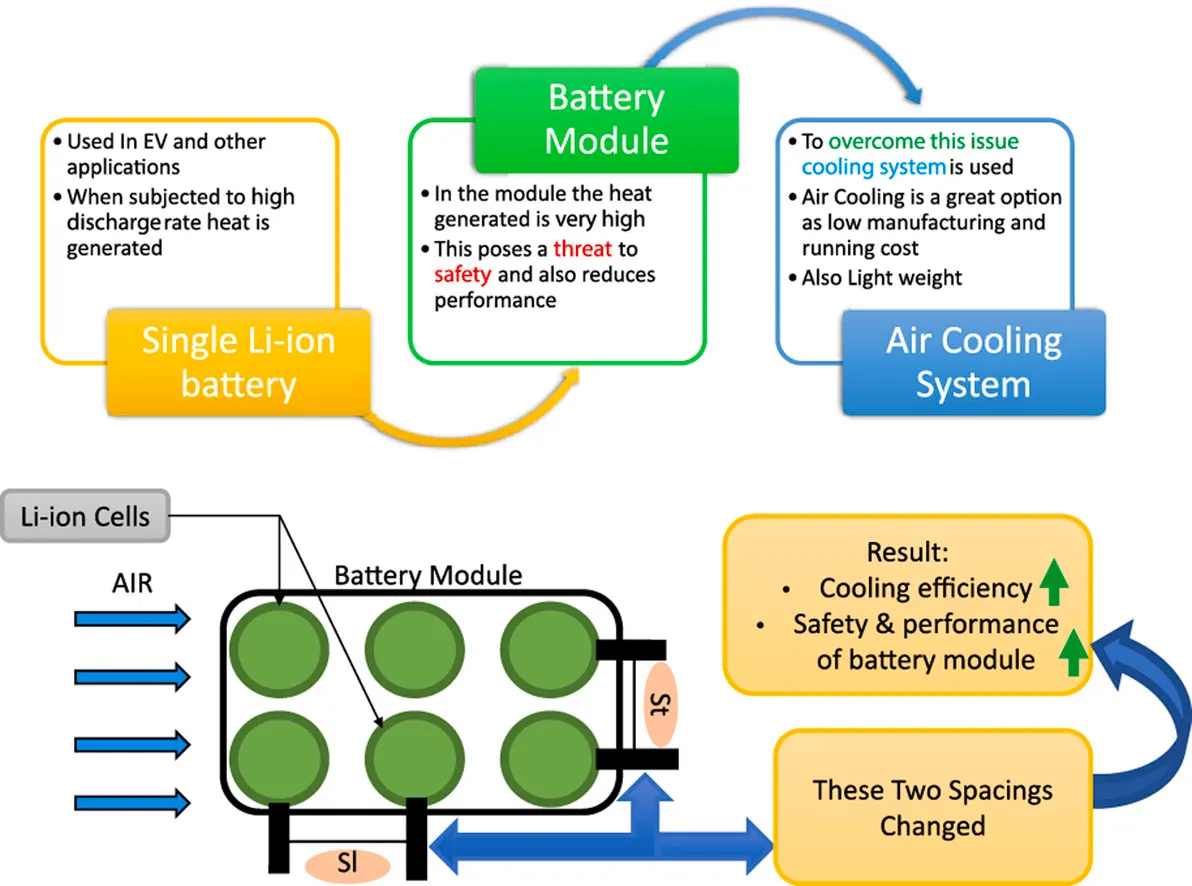
Adiquate gap should be provided to the cells while assembling them, In the electronics applications rechargeable Lithium-ion batteries having a high energy density is a favorable choice. But due to high energy density internal heat generation is a big problem which tends to increase with increasing the discharge rates. This fact makes thermal management an essential part of the Lithium-ion battery management system. The current study focuses on the use of forced air for cooling of a battery module consisting of 30 Lithium-ion batteries. Numerical models for a single Lithium-ion battery and a battery module cooling system are built for analysis of the system and are validated using data from previous studies. The effect of variation in longitudinal and transverse spacing between batteries on various evaluation parameters is studied. Further, for the optimized battery module the effect of flow velocity and discharge rate is studied resulting in a graph of Nusselt number versus Reynolds number. It is observed that the cooling efficiency factor is prominently affected by the transverse spacing and the temperature uniformity by the longitudinal spacing between the batteries. The current study helps in the selection of the battery module spacing for an optimized value of evaluation parameters.
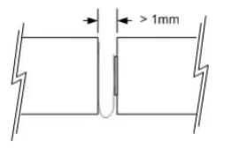
The cell vents, located on the end cap(s) of the cells (on the POSITIVE side of the cell), should not be blocked by any mechanical means. Blocking the cell vent and then sufficiently abusing the cell to build up pressure in the cell prevents the cell from properly venting. An ESS designed to install cells end-to-end needs at least 1 mm of space between the cells to allow the vent to open under fault conditions.
- Cell Assimbling for Battery Pack:
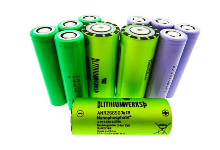
The cell assembling plays a vital role in the battery pack. we consider the cell shape and assembling pattern to assemble them, moslty we prefer cylinderical cells for battery pack. The cylindrical cells are most common type of cells in the market and teh cylindrical cell design enables better automation processes and techiniques and that will increase the consistence and reduce the cost. Cylindrical cell architecher of cells may produce much kWh of power in less time compared to other type cell architecture (like prismatic and etc...). Cylindrical cells can provide a better automation process and techniques that increase consistency and can handle high internal pressures without deforming. They can be produced at a much faster rate and are much cheaper than prismatic cells. They also have better temperature control than prismatic cells. Cylindrical cells are the preferred cell by most manufacturers due to their lower cost, but prismatic cells are great if space is your concern. Luckily, the technology surrounding prismatic cells is improving due to the demand for smaller batteries. The electrodes in a cylindrical cell are wound tightly and encased in a metal casing, This minimizes electrode material from breaking up from the mechanical vibrations, thermal cycling from charging and discharging and mechanical expansion of the current conductors inside from thermal cycling. Many cells are combined in series and in parallel to increase voltage and capacity of the battery pack. If one cell goes bad, the impact on the entire pack is low. With prismatic cells if one cell goes bad it can compromise the whole battery pack. Cylindrical cells radiate heat and control temperature more easily than prismatic cells.
Issues like mechanical vibrations, thermal cycling from charging and discharging, and the mechanical expansion of current conductors are all things that can affect a battery's lifespan. Therefore, the design of these cylindrical units is intended to help mitigate risk from these and other factors as much as possible.On the inside of a cylindrical battery, a series of cells are combined and operate in parallel to one another. This is done to help increase both the voltage and the overall capacity of the battery pack.
For these reasons, cylindrical batteries are usually the kind that are found in the aforementioned medical device systems. Smaller, more specially designed cylindrical cells are also commonly found in portable devices like laptop computers. Notably, Tesla also made headlines recently by selecting cylindrical lithium batteries to power its fleet of popular electric cars.
- Cell connectivity: (Series, Parallel and Series-Parallel)
Series connections:
Series connections involve connecting 2 or more batteries together to increase the voltage of the battery system but keeps the same amp-hour rating. Keep in mind in series connections each battery needs to have the same voltage and capacity rating, or you can end up damaging the battery. To connect batteries in series, you connect the positive terminal of one battery to the negative of another until the desired voltage is achieved. When charging batteries in series, you need to utilize a charger that matches the system voltage. We recommend you charge each battery individually, with a multi-bank charger, to avoid an imbalance between batteries.
In the image below, there are two 12V batteries connected in series which turns this battery bank into a 24V system. You can also see that the bank still has a total capacity rating of 100 Ah.
Parallel connections:
Parallel connections involve connecting 2 or more batteries together to increase the amp-hour capacity of the battery bank, but your voltage stays the same. To connect batteries in parallel, the positive terminals are connected together via a cable and the negative terminals are connected together with another cable until you reach your desired capacity.
A parallel connection is not meant to allow your batteries to power anything above its standard voltage output, but rather increase the duration for which it could power equipment. It’s important to note that when charging batteries that are connected in parallel, the increased amp-hour capacity may require a longer charge time.
In the example below, we have two 12V batteries, but you see the amp-hours increase to 200 Ah.
Series-Parallel Connections:
Series-parallel connection is when you connect a string of batteries to increase both the voltage and capacity of the battery system. For example, you can connect six 6V 100Ah batteries together to give you a 24V 200Ah battery, this is achieved by configuring three strings of two batteries. In this connection you will have two or more sets of batteries which will be configured in both series and parallel to increase the system capacity.
Nickel strips:
Pure nickel strip is the premier material for battery connections in critical applications including: power tools, oil pipelines, hybrid electric vehicles, consumer electronics, pacemakers, aerospace and defense.
Powder metallurgy strip process produces high purity nickel strips which are uniquely suited for battery applications. Very low impurity levels are achievable and dispersed phase alloying approaches can be utilized to advantage. Tight control over low level alloying additions is also an inherent advantage, using wrought powder metallurgy technology process enables us to produce high conductivity materials used in collectors and connector tabs for many battery chemistries. high purity 99.98% nickel strip offers major advantages in rechargeable battery production, those are
- Consistent Chemistry Control.
- Short Lead-times.
- Highest degree of electrical conductivity.
- Lowest electrical resistivity available in pure nickel strip.
- Homogeneity, microcleanliness, and close composition control to enhance weldability.
- Low levels of surface oxides to reduce die wear and provide excellent solderability.
- Excellent formability.

Cell Holders: (Top and Bottom)
A battery holder is one or more compartments or chambers for holding a battery. For dry cells, the holder must also make electrical contact with the battery terminals. For wet cells, cables are often connected to the battery terminals, as is found in automobiles or emergency lighting equipment.
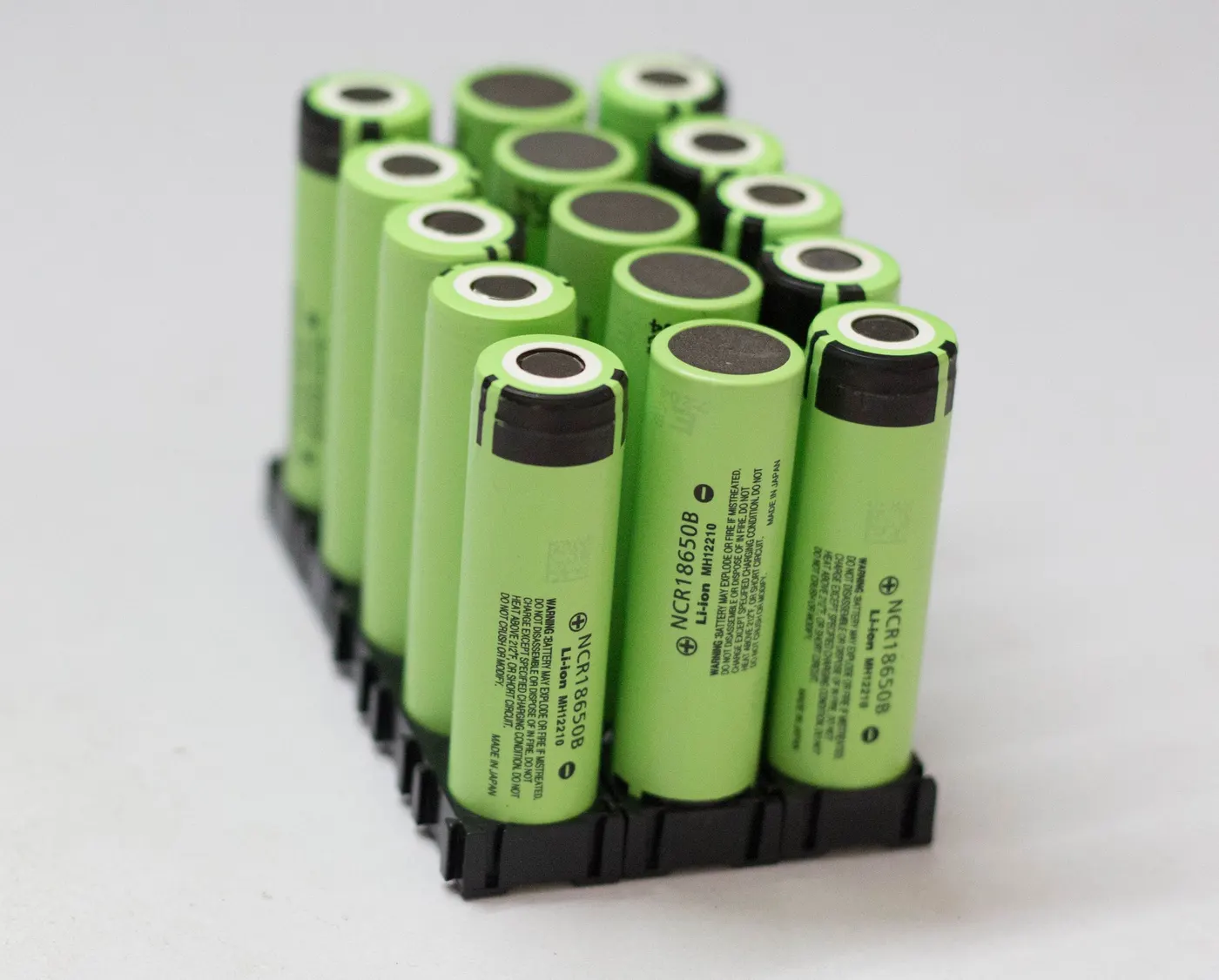
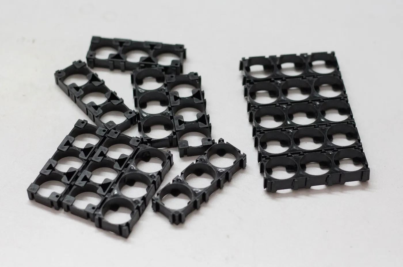
After selecting the cell holders, we insert the batteries in the holders (top and bottom). After inserting the batteries we connect the batteries according the series-parallel connection requirements with the ehlp of nickel strips or with other conductive materials with the help of spot welding or soldering or with external heat source.
I prefre sopt welding to make connections between the cells, the reason for preffering spot welding is The reason we spot weld because it securely joins the cells together without adding much heat to them. There are two grades of spot welders currently available in the market, whereas a good professional grade may cost around ten times more. After making the series-parallel connections between the cells the battery pack looks like the below attached image,
After inserting the batteries in to the cell holders and making the series-parallel connections between the cells, we are few steps away to enclose the battery pack in to the battery enclosure.
Those steps are,
- BMS (battery management system) installation.
- Cooling structure installation.
After these two steps we can install the battery pack into the battery pack enclosure.
BMS (Battery Management System) Installation:
Today’s electronic devices have higher mobility and are greener than ever before. Battery advancements are fueling this progression in a wide range of products from portable power tools to plug-in hybrid electric vehicles and wireless speakers. In recent years, the efficiency of a battery in terms of how much power it can output with respect to size and weight has dramatically improved. Think about how heavy and bulky a car battery is. Its main purpose is to start the car. With recent advancements, you can purchase a lithium-ion battery to jump start your car, and it only weighs a couple of pounds and is the size of your hand.
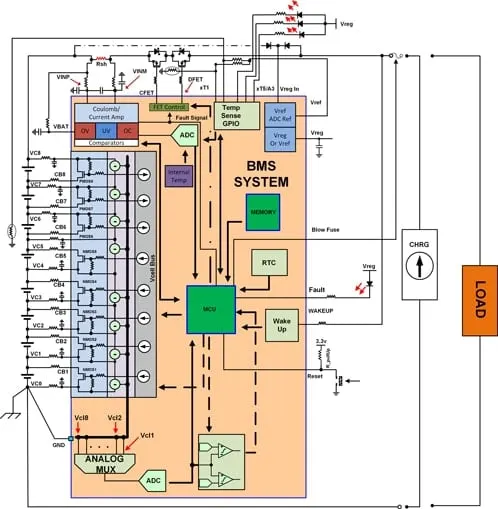
A battery management system can be comprised of many functional blocks including: cutoff FETs, a fuel gauge monitor, cell voltage monitor, cell voltage balance, real-time clock (RTC), temperature monitors, and a state machine. There are many types of battery management ICs available. The grouping of the functional blocks varies widely from a simple analog front-end that offers balancing and monitoring and requires a microcontroller (MCU), to a standalone, highly integrated solution that runs autonomously. Now, let’s take a look at the purpose and the technology behind each block, as well as the pros and cons of the technology.
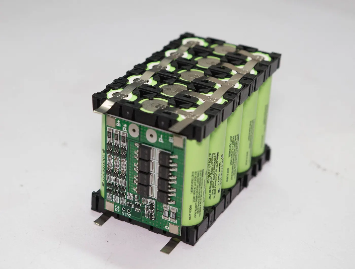
Cooling structure Installation:
With the development of electric vehicles, much attention has been paid to the thermal management of batteries. The major concerns with Lithium-ion batteries failures are temperature rise and temperature non-uniformity during adverse operating conditions like fast charging/discharging and extreme ambient conditions (extreme hot/cold weather). These problems lead to safety issues like thermal runaway of the battery pack. To negate these issues and to ensure better performance of the battery pack, battery thermal management system (BTMS) is adopted in EVs. The prominent BTMSs are air-based BTMS, liquid-based BTMS and phase change based BTMS. This paper collates various thermal management issues and numerous cooling methods developed to mitigate these problems and throws light on some of the research gaps on recovery and utilization of low-grade heat generated in the battery pack.
Air based cooling system,
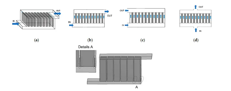
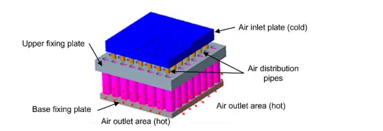
Liquid based cooling system,
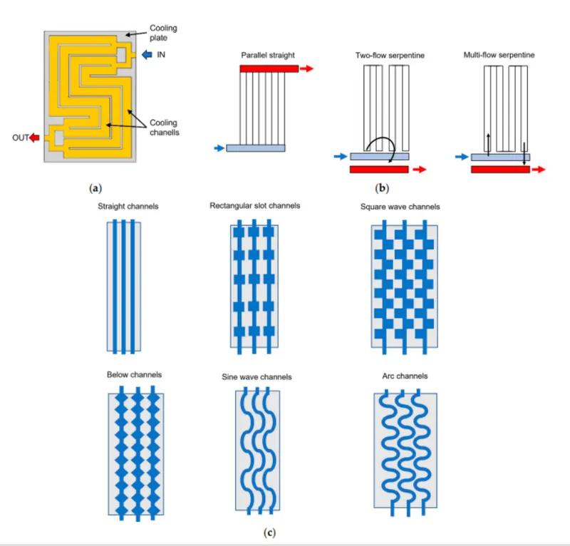
Now the final step in designing a battery pack mechanically is installation of battery pack into the battery enclosure.
Battery Enclosures:
Battery enclosure assemblies safeguard the batteries in electric and hybrid vehicles from puncture or intrusion, thereby protecting passengers and others, as well as the environment, from potentially hazardous conditions. Structural battery enclosures must meet lightweight targets to achieve overall vehicle dynamics.
Distributing the power electronics near to the systems which they control, not only reduces the length of cables required but also simplifies vehicle architecture, facilitating easier maintenance. When designing the packaging for Power Electronics several important factors must be considered; it must provide secure insulation, conduct current, and be electro-magnetically and thermo-mechanically reliable. Incorporation of power electronics within the structure of the electric vehicle (for example, the battery management system incorporated into the structure of the battery pack housing) would save weight, and release space for future EV design and innovation. Distributing the Power Electronics near to the systems which they control, not only reduces the length of cables required but also simplifies vehicle architecture, facilitating easier maintenance. Additional weight and cost savings can be made by combining the cooling of the electronics and the battery using the same heat exchange system.
A new battery box concept would have the following design goals:
- Lightweight – Optimised use of materials.
- Distributed electronics - Merge the power electronic and battery cooling system.
- Modular design – Individual circuits or battery cells can be replaced.
- Shock and vibration proof.
- Fire protection.
- Prevention of electromagnetic radiation.
The battery pack enclosures are unique for each and every electric car, on the basis of battery pack design and vehicle architecture the battery pack enclosures can be designed. The battery pack must attain the above mentioned goals for safer and longer battery life.
References:
- https://www.batteryspace.com/prod-specs/6610.pdf (Battery datasheet).
- https://en.wikipedia.org/wiki/Battery_pack
- https://epicpower.es/wp-content/uploads/2020/08/AN028_SoC-SoH-SoP-definitions_v3.pdf
- https://www.pveducation.org/pvcdrom/battery-characteristics/battery-charging-and-discharging-parameters
- https://www.linkedin.com/pulse/some-important-points-before-designing-li-ion-battery-yadav
- https://relionbattery.com/resource-center/technology/why-choose-lithium
- https://www.uic.com/igbt-power-modules/#:~:text=IGBT%20is%20the%20short%20form,used%20as%20an%20electronic%20switch.
- https://www.lithiumion-batteries.com/cylindrical-vs-prismatic-cells.php
- https://blog.epectec.com/lithium-batteries-cylindrical-versus-prismatic
- https://www.power-sonic.com/blog/how-to-connect-batteries-in-series-and-parallel/
- https://relionbattery.com/blog/series-vs-parallel-connections-explained#:~:text=Series%20connections%20involve%20connecting%202,end%20up%20damaging%20the%20battery.
- https://ph.rs-online.com/web/generalDisplay.html?id=ideas-and-advice/battery-holders-guide
- https://www.renesas.com/kr/en/products/power-power-management/battery-management-system-tutorial