Project 1 Mechanical design of battery pack
Nanophosphate Technology26650 Lithium Ion Power Cell
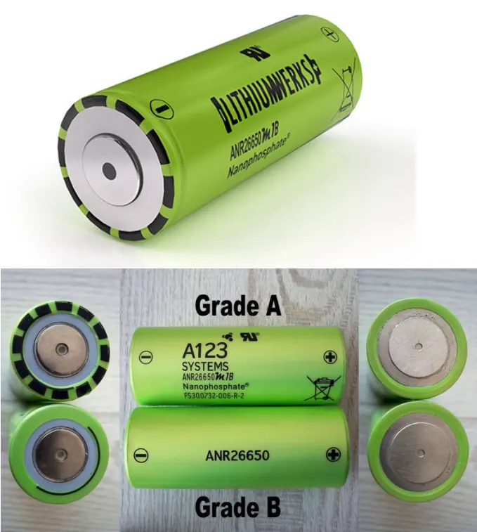
26650 cells are capable of delivering very high power due to its use of patented Nanophosphate battery technology. Based on lithium iron phosphate chemistry(LiFeP04), the cells are inherently safe over a wide range of temperatures and conditions.Whether the application requires outstanding cycle life or stable float reliability, the Lithium-ion 26650 cells are suitable for a wide variety of power, pulse, or stand-by applications.
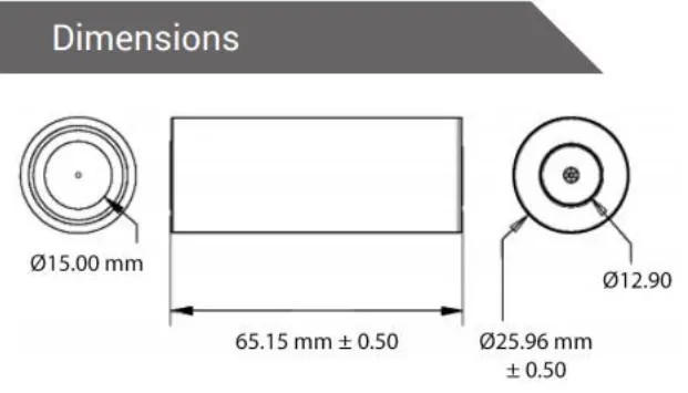
Nanophosphate battery technology offers stable chemistry, faster charging, consistent output, excellent cycle life and superior cost performance. It provides the foundation for safe systems while meeting the most demanding customer requirements. Multiple layers of protection are employed at the chemistry, cell and system level to achieve an energy storage solution with superior safety and abuse tolerance compared to metal oxide lithium-ion chemistries.
Theory of Battery:
cell ; A cell refers to a single anode and cathode separated by electrolyte used to produce a voltage and current. A battery can be made up of one or more cells. A single AA battery, for example, is one cell. +ve/-ve Terminals and
Battery; Batteries are a collection of one or more cells whose chemical reactions create a flow of electrons in a circuit.
Battery Pack : Battery packs are any number of individual batteries arranged in series or parallel to provide the required power to electronic devices. The most common type of battery used in battery packs is lithium-ion due to its high power density. They may be configured in a series, parallel or a mixture of both to deliver the desired voltage, capacity, or power density.
calculation of battery:
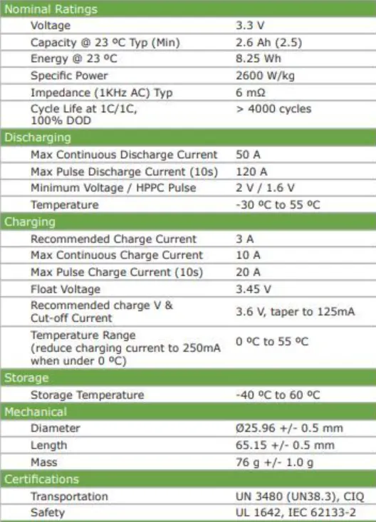
1. Energy= 18KWh (required)
2. Number of cells(N) = energy/(nominal voltage*capacity)
N=18000/(3.3*2.5)
N=2182 We need a minimum of 2182 cells to get 18kWh energy, now based on that, we need to decide configuration -series and parallel.
The nominal voltage of one cell = 3.3V Number of cells required to connected in series connection to produce 330V(Ns) = voltage required/nominal voltage of one cell
Ns=330/3.3
Ns=100
100 cells connected in series will generate 330 voltage and the capacity of the whole module will be 2.SAh.
Now we need to find the number of cells which will be connected in a parallel configuration
Np(cell in parallel)= total cell/ Ns
Np=2182/100
Np=21.82
Several cells can't be infracted, so we take 22 cells for each parallel row
Cell architecture= 100Series and 22Parallel = 100522P
3. Battery capacity
We know parallel configured cell multiplies individual cell capacity so,
Capacity= parallel cell row*individual cell capacity
Capacity =2.5*22
Capacity = 55.0Ah
4.Current supplied by the battery
We have already calculated battery capacity which is 55.0Ah means it is going to supply SSA current per hour. which can be considered as Crate.
5.Range
Let's powertrain energy consumption= 129 Wh/Km at 70% powertrain efficiency
Range= Capacity/ energy consumed per kilometre
Range= 18000/129
Range= 139Km
6.Internal Resistance of Battery:
The entire resistance encountered by a current as if it flows through a battery from the negative terminal to the positive terminal is known as internal resistance of battery.
7.Battery Dimension:
ANR26650 cell has 26mm diameter and 65mm height.
On the basis of that we need to decide battery size of battery casing.
Length of casing(L) = number of cells at mid*(cell diameter (26) + margin at both side of cell (4)) + clearance at side (diameter of edged cell + margin)
L=98*30 + 60
L=3000mm
Breadth of casing(B) = cell diameter (26) + margin at both side of cell (4) + clearance at side (diameter of edged cell + margin)
B=20*30 + 60
B=660mm
Height of casing(H) = 65+35
H=100mm
7.Weight of battery pack
Cell weight = 7 6g
Number of the cells= 2182
Battery pack weight(W) = cell weight*number of cells + weight of accessories
W = 76*2182 + 4.5 = 165.8 + 4.5 =170.3Kg
Battery Pack Assembly (Series /Parallel Batteries):
Battery cells can be connected in series, in parallel and as well as a mixture of both the series and parallel.
1.Series Batteries:
When in a battery.positive terminal of one cell is connected with the negative terminal of succeeding cell, then the cells are said to be series connected or simply series battery . Here, overall emf of the battery is algebraic sum of all individual cells connected in series. But overall discharged current of the battery does not exceed the discharged current of individual cells.
2.Parallel Batteries:
When positive terminals of all cells are connected together and similarly negative terminals of these cells are connected together in a battery , then the cells are said to be connected in parallel. These combinations are also referred as parallel batteries.
3.Mixed Grouping of Batteries or Series Parallel Batteries:
The cells in a battery can also be connected in mixture of both series and parallel. These combinations are some time ref erred as series parallel battery . A load can require both voltage and current more than that of an individual battery cell. For achieving the required load voltage, the desired numbers of battery cells can be combined in series and for achieving the required load current, desired numbers of these series combinations are connected in parallel. Let m, numbers of series, each containing n numbers of identical cells, are connected in parallel
Required Components of Battery Pack Assembly Tools:
Required -2200 cells, Nickle strips, PVC heat sink film, Spot welder, Connectors, Cell holder and Solder.
Step 1: We are going to start with snapping square cell holder together. One can use cell terminal blocks, but they will consume more space than hexagonal holder.
Jut insulator gasket on the positive side of cell.
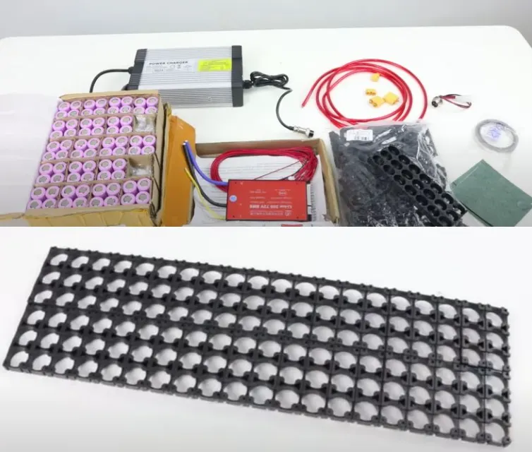
fig. components of battery pack

fig. cell with insulator gasket
Step 2: Now place cells in cell holder matrix. After loading all cells put second cell connector block to other side
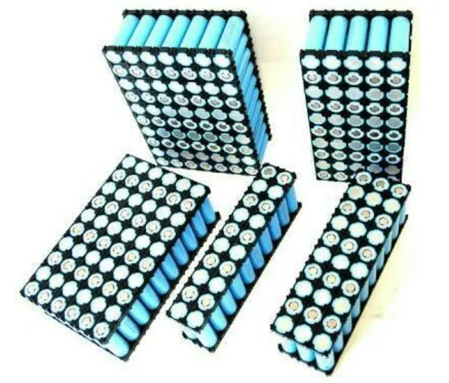
fig. loaded cell into holder
Step 3: Connect cell with nickel strips using spot Nelder. Series connection will be made by :onnecting cell positive to cell negative and parallel connection will be made by connecting same terminals. Weld some nickel strips to terminal cells, which will be later used to ittached balancing wire.
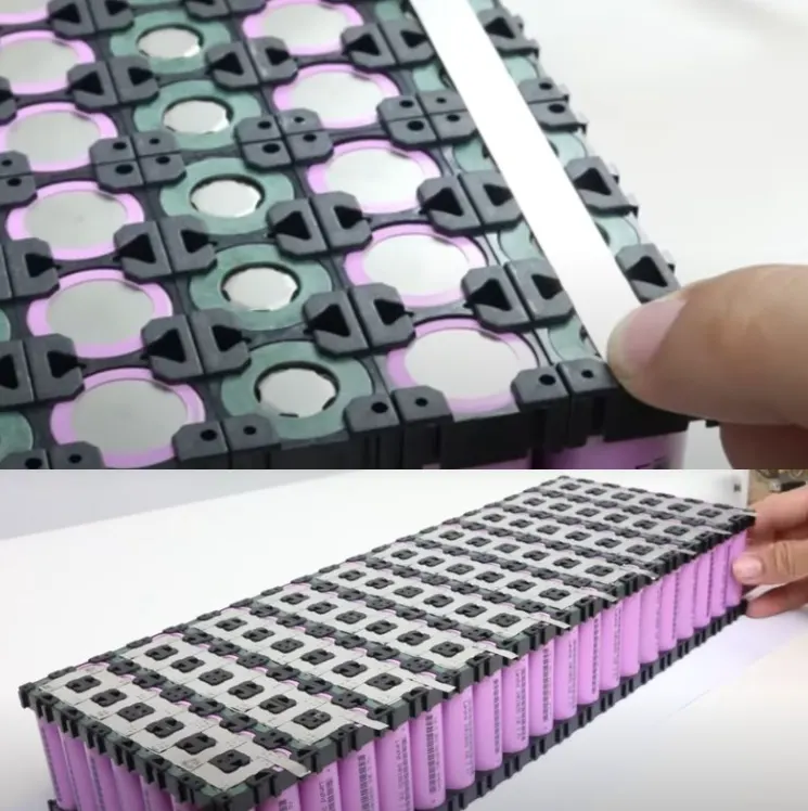
cell connection with nickel strip and the connection matric contain terminal balacing wire
Step 4: After connections, stick PVC heat sink :ilm to cell. solder balancing wire to terminals ind battery management system's current ;upply wire to battery pack.
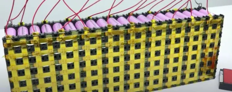
fig.pack with balancing wires
Step 5: Connect balancing wire pin to BMS and glue it to side of battery pack with BMS.
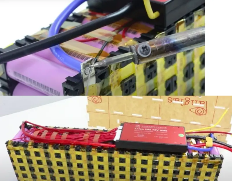
soldering of supply wire and battery pack with BMS
Step 6: Now put battery pack in an enclose, that can be made of plastic, metal or battery pack can be wrapped in a plastic sheet.
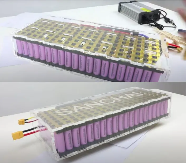
fig. battery in plastic case & battery pack