Project 1 Mechanical design of battery pack
Objective:
Mechanical design of a 18kWh powered battery pack using ANR26650M1-B cells.
Cell data:
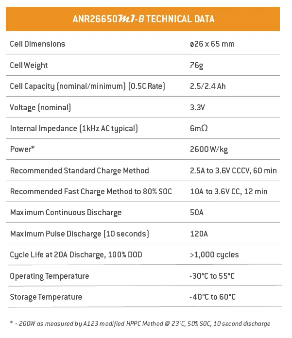
A123’s high-performance Nanophosphate lithium iron phosphate (LiFePO4) battery technology delivers high power and energy density combined with excellent safety performance and extensive life cycling in a lighter weight, more compact package. Cells have low capacity loss and impedance growth over time as well as high usable energy over a wide state of charge (SOC) range, allowing our systems to meet end-of-life power and energy requirements with minimal pack oversizing.
Cell calculations:
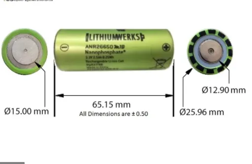
Cell volume = π * r * r * h
= 3.14 * 0.013 * 0.013 * 0.065
= 0.0026533 m^3
Cell energy = Nominal voltage * Nominal cell capacity
= 3.3 * 2.5
= 8.25 Wh
Cell energy density = cell energy/cell volume
= 8.25 / 0.0026533
= 3.11 kWh/m^3
Battery pack assumptions:
- There are 46 cells in series and 48 cells in parallel of the battery pack.
- All the cells are ANR26650M1-B type.
Battery pack calculations:
Total numer of cells = 46 * 48
= 2208 cells
Voltage = Nominal voltage of a cell * number of cells in series
= 3.3 * 46
= 151.8 V
Capacity = Nominal cell capacity * number of cells in parallel
= 2.5 * 48
= 120 Ah
Energy = Voltage * Capacity
= 151.8 * 120
= 18216
= 18.216 kWh
Volume = Cell volume * Total number of cells
= 0.0026533 * 2208
= 5.86 m^3
Energy density = Battery pack energy / Volume
= 18216 / 5.86
= 3.11 kWh/m^3
Weight = Total numer of cells * Cell weight
= 2208 * 0.076
= 167.81 kg
Battery pack construction:
A battery pack is a system of multiple components and functions and its design involves the application of knowledge and practice in the electrochemical, electrical, mechanical, thermodynamic, and control fields. The following sections summarize the various stages of a battery pack design, covering specific aspects of the cells which may be unique from other cells.
- The first step in the design of the pack is to determine the configuration of cells, i.e. how many cells overall, how many are in series, and how many are in parallel. This is the foundation of the design process, since all other design decisions follow from the cell configuration.
- The second step is to design a mechanical structure around the cells to support and protect them. This step requires knowledge of electrical, mechanical and thermodynamic requirements and properties of the cells, application, and the materials used in the pack.
- The third step is to design the protection of the cells, particularly electrical protection. The pack must be protected from inadvertent short circuits internal and external to the pack as well as excessive charging and discharging imposed on its terminals.
- The fourth step is to design a control system that monitors and manages the cells, keeping them from being damaged and maintaining the pack at peak performance.
- Finally, a pack performs best when it is used properly. The final section of this chapter describes how to charge and discharge the battery pack to make it perform its best.
Mechanical connection :
It interconnects to prevent accidental short circuits. These mechanical interconnects carry the expected maximum rated current for both the maximum time and ambient temperature in which the pack is expected to operate.
Cell interconnects :
Cell interconnects were designed for the expected maximum current carrying capability. Improper sized tabs could heat up excessively, resulting in even higher resistivity. For reliable welded connections at the terminals, A123 Systems recommends either pure nickel tabs or nickel-clad copper tabs. In addition, other alloys afford both the weldability, strength and low resistance, which are all desirable features of a good interconnection. Cell interconnects (tabs) should be neither soldered on the end caps nor attached using extreme heat. A123 Systems recommends tabs be resistance or laser-welded to both ends of the cells. Resistance welding provides a constant current for a specified period of time through a salient feature in the weld tab. These parameters can be specified and regulated for a consistent high-quality weld every time.
The gap between each cell :
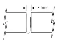
The cell vents, located on the end cap(s) of the cells (on the POSITIVE side of the cell), should not be blocked by any mechanical means. Blocking the cell vent and then sufficiently abusing the cell so as to build up pressure in the cell prevents the cell from properly venting. An ESS was designed to install cells end-to-end and needs at least 1 mm of space between the cells to allow the vent to open under fault conditions.
Cell dimmensions :
Series strings:
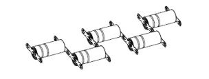
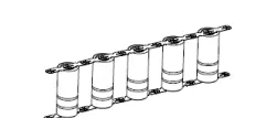
Cells combined in series strings can achieve higher operating voltages by connecting the positive terminal of one cell to the negative terminal of the next cell. Connect strings of series cells using their current collection tabs in a manner similar to that illustrated in figure.
Parallel strings :
Cells combined in parallel strings can achieve higher operating capacities by connecting like-polarity terminals of adjacent cells to each other. Connect strings of parallel cells using their current collection tabs in a manner similar to that illustrated in figure .
Nickel Strips:
Conductive metal strips were spot welded between all the cells of a battery pack. Nickel is used due to its low relative resistance and ease of spot welding.

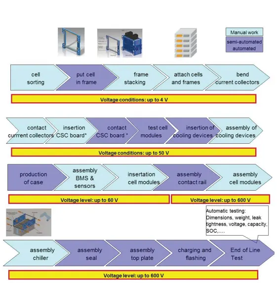
Battery pack production line:
Model of a battery pack: