Project 1 Mechanical design of battery pack
Introduction to Battery Technology for Electric Vehicles using MATLAB & Simulink
Project 1 Mechanical design of battery pack
Q . Battery pack capacity: 18 kWh
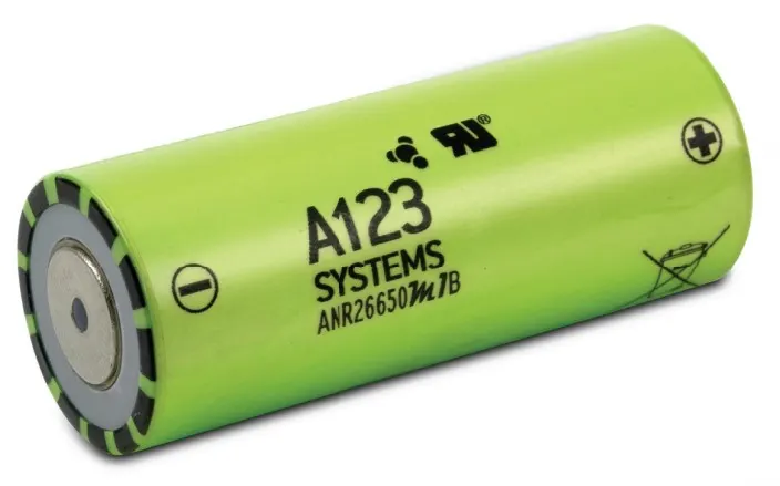
Cell: ANR26650M1-B
Prepare a detailed battery pack drawing along with its enclosure. State your assumptions.
Ans=>
The battery pack being designed is made by using the cell ANR26650M1-B:
Nanophosphate® High Power LithiumIon Cell ANR26650M1-B
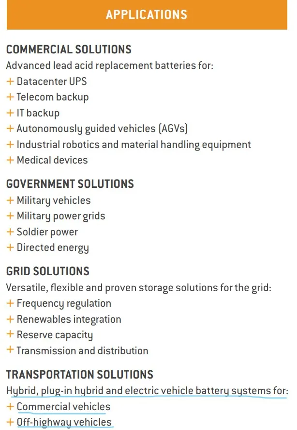
A123’s high-performance Nanophosphate® lithium iron phosphate (LiFePO4) battery technology delivers high power and energy density combined with excellent safety performance and extensive life cycling in a lighter weight, more compact package. Our cells have low capacity loss and impedance growth over time as well as high usable energy over a wide state of charge (SOC) range, allowing our systems to meet end-of-life power and energy requirements with minimal pack oversizing.
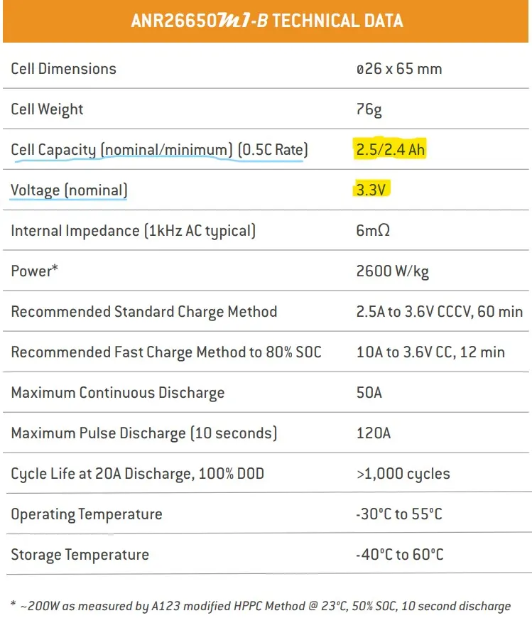
The cell has a lithium iron phosphate (LiFepO4) chemistry. The following table gives the overview of specifications of the cell.
We have,
Cell nominal voltage = 3.3V
Cell nominal capacity =2.5 Ah
, the cell energy capacity is the product of these two parameters = 3.3V × 2.5Ah = 8.25 watt-hr.
The required battery energy capacity is 18 KWh.
Let take module of 3s & 5p
i.e The voltage of each module will be
=> 3S × 3.3V = 9.9V
& The capacity of each module will be
=> 5P × 2.5Ah= 12.5Ah
Thus we have single module of 9.9V & 12.5Ah Capacity.
Let us assume 48V battery pack.
To make this voltage battery pack we need no. of module in series ,
NSM = 48V/9.9V = 4.8 =5 module (series)
i.e 5 module in series connection required to get 48V battery system.
To get a pack energy of the battery = 18000 wh,
=> 18000 Wh/ 48V = 375 Ah
Which can be get by connecting module in parallel,
To make this pack energy capacity battery we need no. of module in parallel ,
NPM = 375 Ah/ 12.5Ah = 30 module (parallel)
i.e 30 module in parallel connection required to get 375Ah battery system.
Thus we required 5S(module) & 30P(module) while each module has 3S & 5P no. of cell.
i.e Total capacity we get as,
= 5SM × 30PM × (3S × 3.3V) × (5P × 2.5Ah)
= 18,562.5 Wh 18KWh (Battery pack)
The additional energy can be used to compensate for the losses in the battery due to external environmental conditions. The margin can be designed according to the type of application, and in a controlled environment, this margin remains small.
Assumptions:
- The vehicle in which this power is being used is the power the Plug-in hybrids vehicle , Some small capacity full electric vehicles like Mitsubishi i-MIEV, E-rickshaw, etc.
- The battery pack is air cooled.
-Making the battery pack
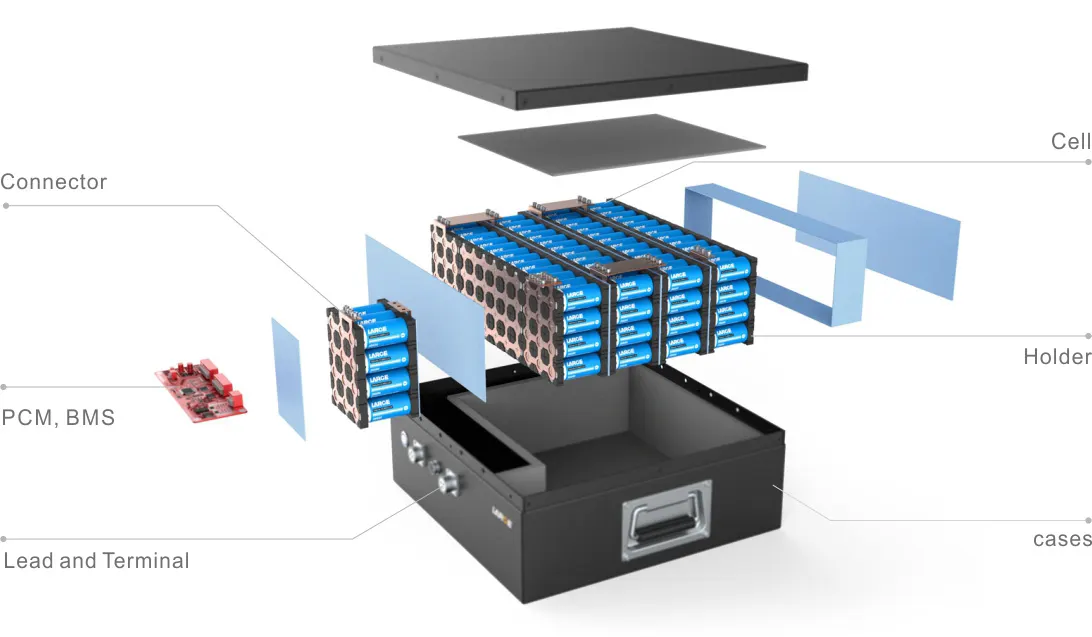
The battery pack should be made out of the materials that isolates the cells inside it from external conditions. The pack should have excellent mechanical properties , should be impact resistant, heat resistant, crack resistant, across various temperature ranges. The pack should be stiff to ensure the compactness.
The 3S5P connection of ANR26650M1-B cell is shown below

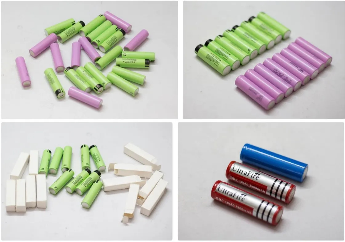
Step 1: Select the ANR26650M1-B Cells for the Battery Pack
Step 2: Choosing the Right Battery Strips
To make the battery pack, you have to connect the ANR26650M1-B cells together by means of Nickel strips or thick wire. Generally, Nickel strips are widely used for this. In general two types of nickel, strips are available in the market: nickel-plated steel strips and pure nickel strips. I will suggest buying a pure nickel. It is a little bit costlier than nickel-plated steel, but it has much lower resistance. Low resistance means, less heat generation during the charging and discharging, which leads to longer useful battery life. Nickel strips come with different dimensions and lengths. Choose the strips according to the current rating.
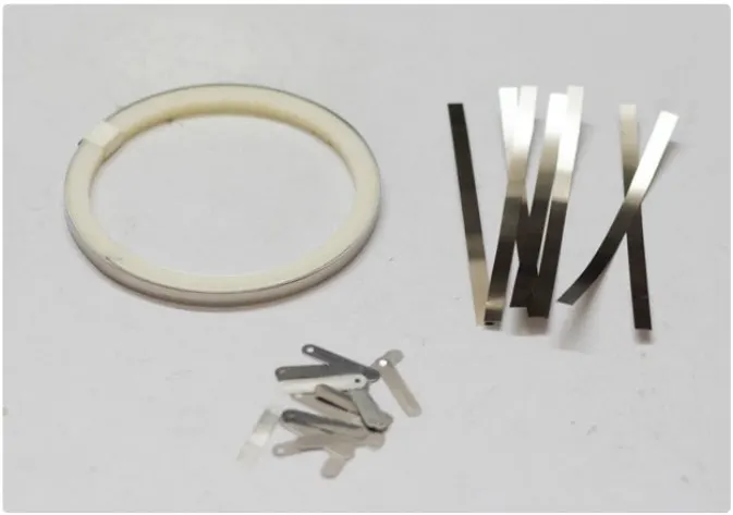
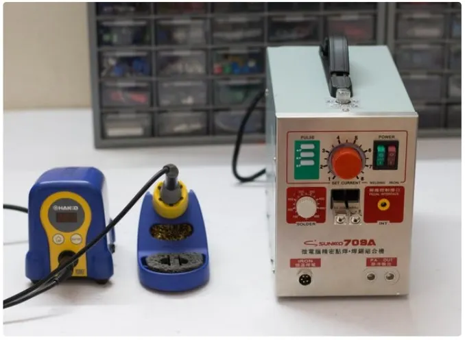
= Spot Welding Vs Soldering
You have two options to connect the cells together: 1. Soldering 2. Spot Welding The best choice is always Spot welding, but Spot Welder is much costlier than a good quality Soldering Iron.
Soldering : You should know why Spot welding is preferred over soldering, the problem with soldering is that you apply a lot of heat to the cell and it doesn’t dissipate very quickly. This enhances the chemical reaction in the cell which damages the cell's performance. Ultimately you will lose some capacity and life the cells.
Spot Welding : The reason we spot weld because it securely joins the cells together without adding much heat to them.
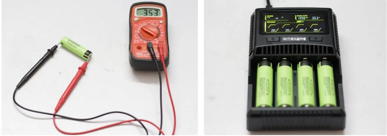
Step 3: Check the Cell Voltage
Before connecting the cells in parallel, first, check the individual cell voltages. For paralleling the cells, the voltage of each cell should be near to each other, otherwise, a high amount of current will flow from the cell with a higher voltage to the cell with a lower voltage. This can damage the cells and even result in fire on rare occasions.
But if you are going to use an old laptop battery, be sure the cell's voltage is nearly the same, otherwise, charge the cells to the same voltage level by using a good Li-Ion Battery Charger.
Step 4: Battery Pack Capacity and Voltage
To make the battery pack, you have to first finalize the nominal voltage and capacity of the pack. Either it will be in terms of Volt, mAh/ Ah, or Wh. You have to connect the cells in parallel to reach the desired capacity (mAh ) and connect such parallel group in series to achieve the nominal voltage (Volt ).
Commonly cells in parallel are abbreviated in terms of ‘P’, so this pack will be known as a “5P pack”.When 5 cells are connected in parallel, ultimately you made a single cell with higher capacity.
Commonly cells in series are abbreviated in terms of ‘S’, so this pack will be known as a “3S pack”.
Step 5: Assemble the Cells
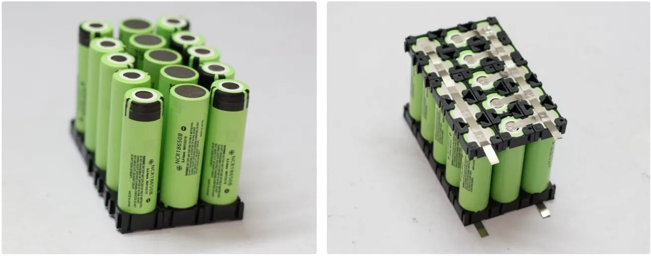
Now we have to arrange the 15 cells properly for making the electrical connection among them and with the BMS board.
Place the first parallel group of cells (5 nos) positive side up, then place the second parallel group negative side up, and then finally the last parallel group positive side up.
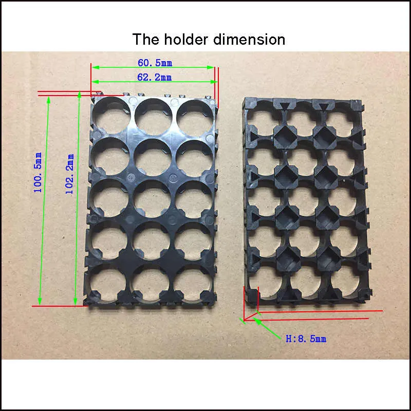
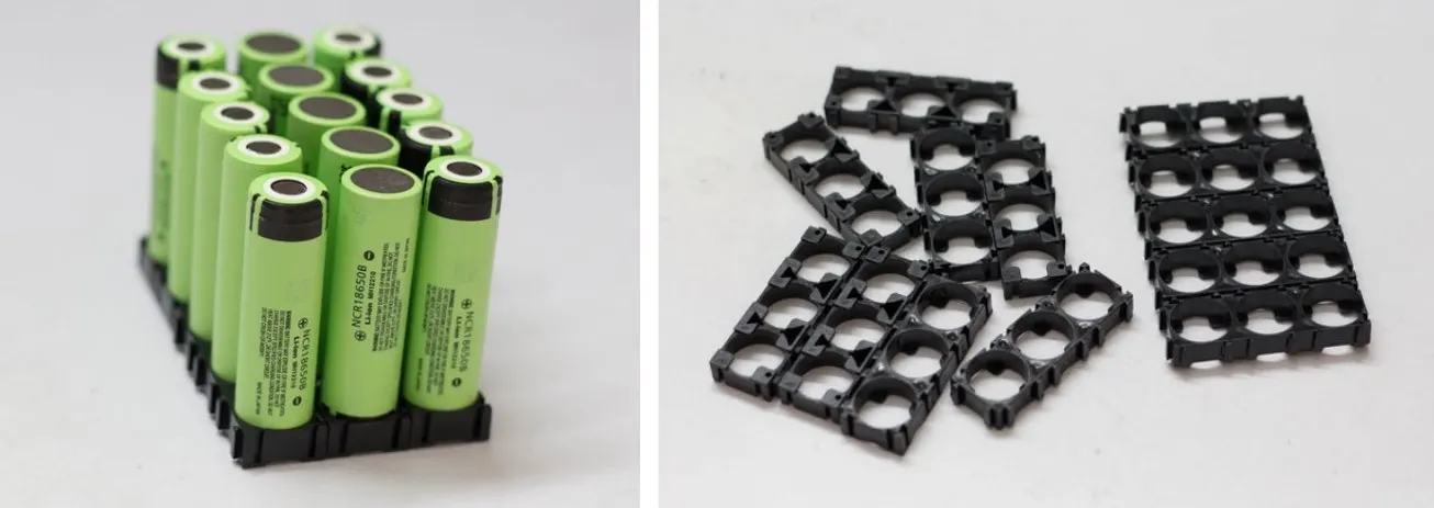
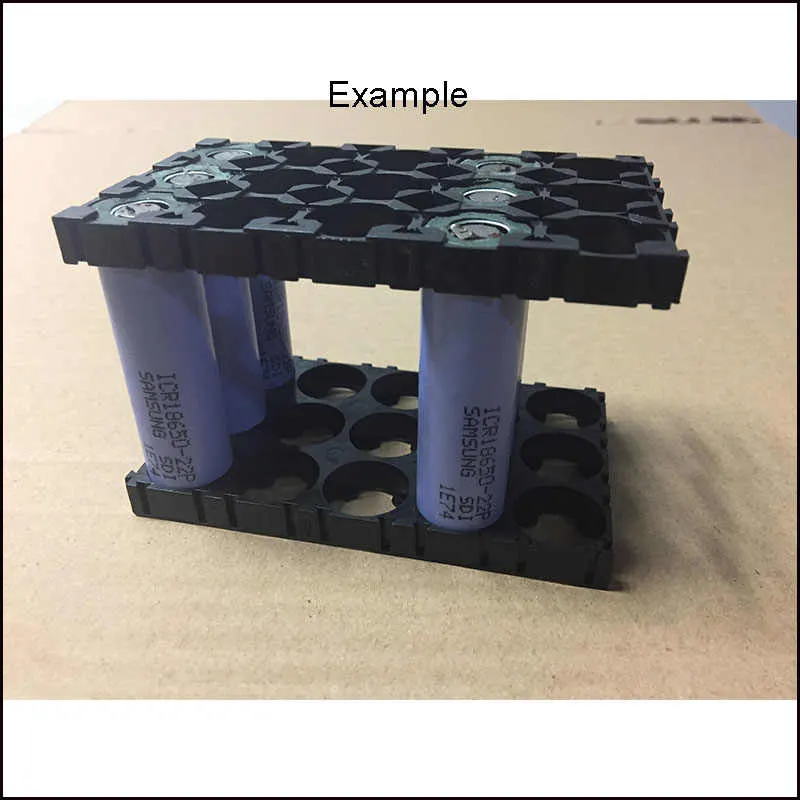
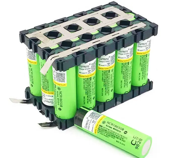
You can assemble the cells to make the pack by using hot glue or by using a plastic battery holder.
The main advantages of using these cell holders are
- You can make a custom pack of any size according to your requirement.It's like solving a puzzle.
- It provides space between the cells, which allow fresh air to pass and the battery gets cooled easily.
- It makes your battery pack solid and reliable.
- It provides safety anti-vibration to your battery pack.
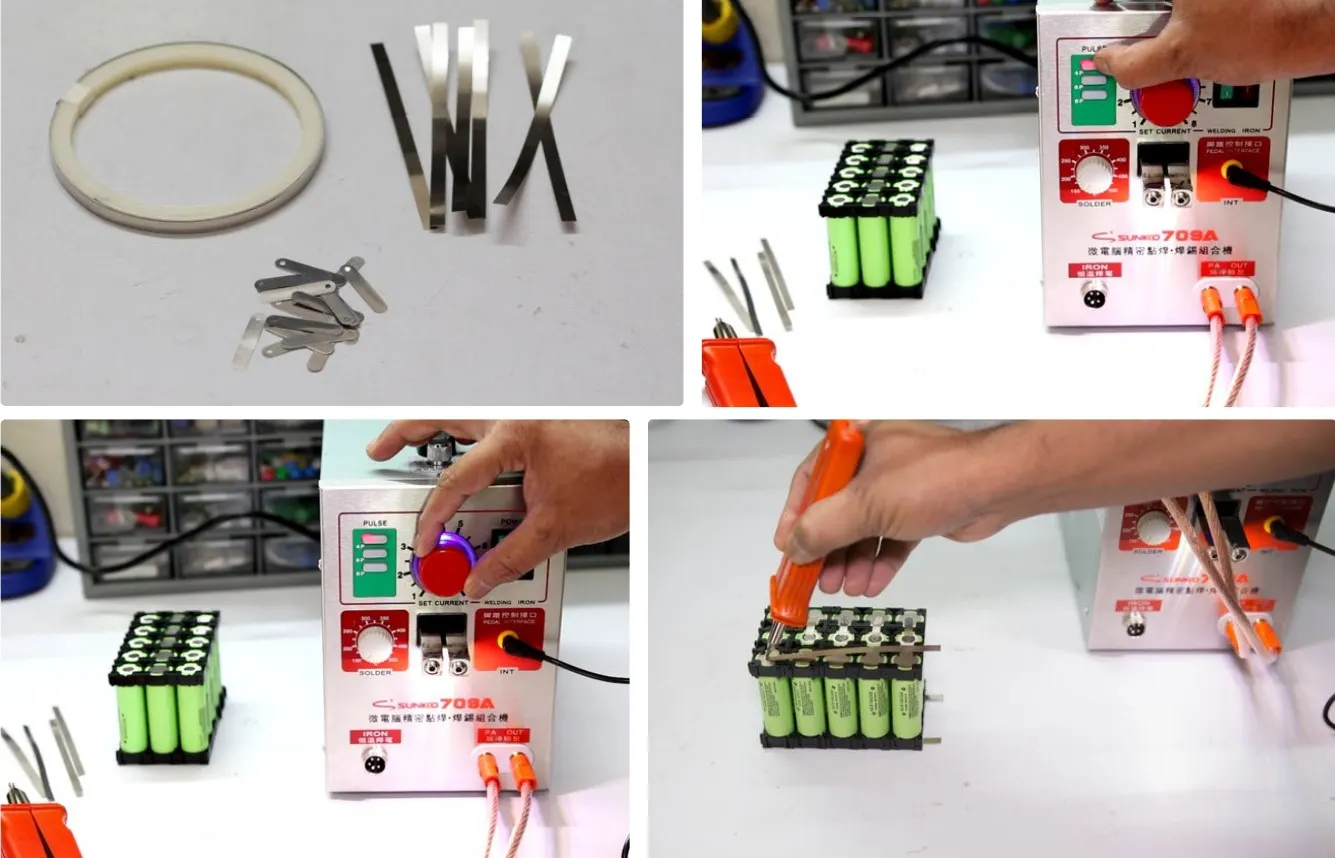
Step 6: Spot Weld the Nickel Strips
Now it is time forthe Spot Welder . The Spot welder has three welding choices: fixed welding head, fixed welding head with foot switch, movable spot welding pen with the foot switch. Before welding, you have to prepare the nickel strips and welder.
Cut the nickel s trips :
Lay your nickel strip on top of the 5 cells ( parallel ), ensuring that it covers all cells terminals, leave 10mm excess strips for connecting it to the BMS, and then cut it. For series connection cut small nickel strips as shown in the figure. You will need four long strips for parallel connection and 10 small strips for series connections. Connect the first parallel group negative terminal to the positive terminal of the second group and then the negative terminal of the second group to the positive terminal of the third group.
Weld the Battery Strips :
This spot welder can be used to weld the pure nickel as well as nickel-plated steel strips. You have to adjust the welder pulse and current knob according to the thickness of the nickel strips. For 0.15 mm nickel strips, press the pulse knob 4P and current knob to 4-5. Similarly for 0.2 mm nickel strip, press the pulse knob 4P,6P, and current knob to 7-8. Make sure the welding pen is compressed with the nickel strip and battery terminal, then press the footswitch. You will notice a small spark and two-dot mark on the strip.
Successful Welding :
You can check the weld quality by pulling on the nickel strip. If it doesn’t come of with hand pressure or requires a lot of strength, then it’s a good weld. If you can easily peel it of, then you have to increase the current.
Safety: Be fore starting the spot welding, always wear safety goggles.
Step 7: Adding the BMS
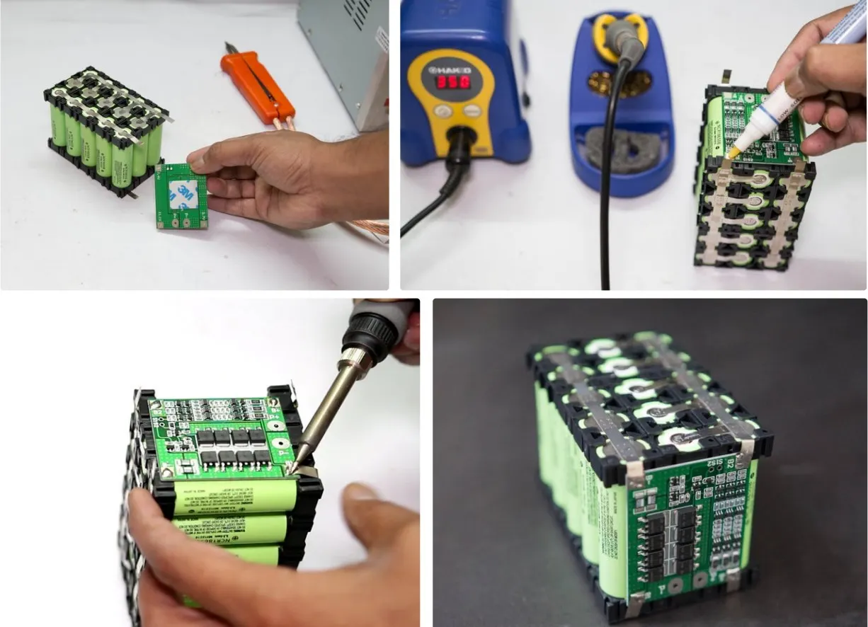
A battery management system (BMS) is an electronic system that manages a lithium battery pack and the main functionalities are
- Monitors all of the parallel groups in the battery pack and disconnect it from the input power source when fully charged.
- Balance all the cells voltage equally
Doesn't allow the pack from over-discharged.
Step 8: Final Assembling
CONCLUSION :
The battery pack has a voltage of 48 volts and 18kwh , which bring us to a design of 15s 150p battery made by using 8s4p modular configuration where 5 of them are arrranged in series and 30 such arranegemnts are connected in parallel.And total no. of cells used =2250 cells.
Reference:-
https://datasheetspdf.com/pdf/1424845/A123Systems/ANR26650M1-B/1
https://www.instructables.com/DIY-Professional-18650-Battery-Pack/