Project 1 Mechanical design of battery pack
Objective:
To create a battery pack drawing of 18KWh using series and parallel connections of battery modules made up of individual Li-ion cells.
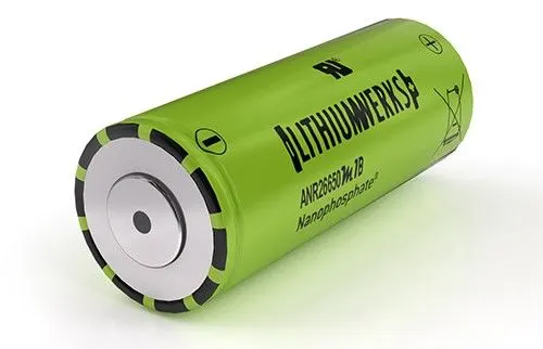
Li-ion cell used hear is of model ANR26650M1-B from the manufacturer of Lithiumwerks.
To discuss about the enclosure used for battery pack.
Li-ion cell(ANR26650M1-B):
Lithiumwerks produces this Li-ion cell. They provide a lot of power since they employ unique Nano phosphate battery technology.
The cells are intrinsically safe across a wide temperature and condition range due to the Lithium iron phosphate chemistry (LiFePO4).
This cell is appropriate for a broad range of power, pulse, and standby applications because to its excellent cycle life and consistent float dependability.
Thermal stability, rapid charging, constant output, and little capacity loss over time are all advantages of nano phosphate battery technology.
It delivers very safe working conditions while satisfying the most stringent client standards. To achieve an energy storage solution with better safety, many layers of protection are used at the chemical, cell, and system levels.
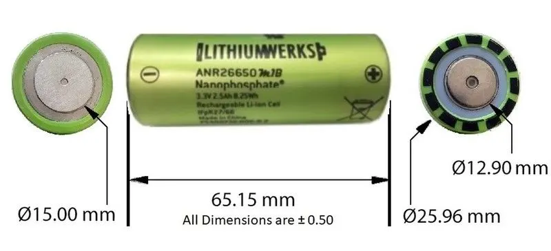
Dimensions:
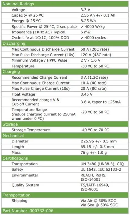
Cell specifications:
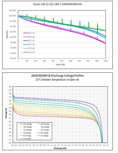
Discharge voltage profile and cycle life with respect to different operating temperature from data sheet:
Assumptions:
We assume that the total voltage required to run the motor and other electric car accessories is 400V.
As a result, we built an 18KWh battery pack for a 400 V input voltage motor.
Cell calculations:
Cell volume = π * r * r * h
= 3.14 * 0.013 * 0.013 * 0.065
= 0.0026533 m^3
Cell energy = Nominal voltage * Nominal cell capacity
= 3.3 * 2.5
= 8.25 Wh
Cell energy density = cell energy/cell volume
= 8.25 / 0.0026533
= 3.11 kWh/m^3
Battery pack assumptions:
- There are 46 cells in series and 48 cells in parallel of the battery pack.
- All the cells are ANR26650M1-B type.
Battery pack calculations:
Total number of cells = 46 * 48
=2208 cells
Voltage = Nominal voltage of a cell * number of cells in series
= 3.3 * 46
= 151.8 V
Capacity = Nominal cell capacity * number of cells in parallel
= 2.5 * 48
= 120 Ah
Energy = Voltage * Capacity
= 151.8 * 120
= 18216
= 18.216 kWh
Volume = Cell volume * Total number of cells
= 0.0026533 * 2208
= 5.86 m^3
Energy density = Battery pack energy / Volume
= 18216 / 5.86
= 3.11 kWh/m^3
Weight = Total number of cells * Cell weight
= 2208 * 0.076
= 167.81 kg
Construction of battery pack:
- To build a battery pack, we must first evaluate the voltage required by the vehicle's entire load.
- As previously stated, we expected 400V.
- The battery modules should then be designed in such a way that the overall voltage matches the voltage required by the load.
- Individual cells can be connected in series or parallel to form modules. The modules should then be joined in series/parallel to form the final battery pack.
In series connection-Voltage added and Current remains same.
In Parallel connection-Voltage remains same and Current gets added.
- In our example, the single cell voltage is 3.3V and the capacity is 2.56Ah. The energy provided by the Sigle cell is 8.25Wh.
- So, for an 18KWh battery pack, we'll require around (18000/8.25=2208 cells).
- To meet our load demand, we must design a single module that generates 400V.
- So, in order to get 400 V output, cells are linked in series, where voltage is added but current stays constant.
- The number of cells necessary to get 400V is about (400/3.3=122 cells).
- Thus, a single module generates 400V from 122 cells, but the energy of one module is insufficient to power the car because the motor power rating is greater. The total energy produced by a single module is (122*8.25Wh=1006.5Wh).
- So to construct a battery pack with 18KWh with not exceeding 400V the modules are connected in parallel. In this parallel connections the currents are getting added and
- The voltage stays at 400V. As current increases, the power of the battery pack increases in order to power the high-power-rated motor load.
- Now we need to figure out how many such modules should be linked in parallel to create an 18KWh battery pack.
- This may be computed as (18KWh/1006.5Wh =17.88), which means that approximately 18 identical modules must be linked in parallel to obtain an 18KWh battery pack.
- As a result, the battery model is said to be 122S18P (122 series and 18 parallel connections), giving us (122*18 = 2196 cells).
- We calculated the entire capacity of the battery pack as (2196*8.25Wh=18117Wh), which is slightly greater than 18KWh.
- The total capacity (Ah) of the battery pack is (2.5Ah * 18 = 45Ah).
- That is, it supplied 45 A of continuous current for one hour until full discharge.
- As a result, 18 modules need be assembled as a battery pack to fit in an EV chassis.
Enclosure construction:
To get the overall enclosure volume, multiply the volume of a single module volume (122 cells in series) by the volume of 18 parallel linked module volumes.
Single module,
Let as assume 122 cells (single module) are divided into 2 modules of 61+61 cells.
The length of the module=No.of cell in row*(Cell dia + Margin at both side of cells) + clearance at side (2(cell dia + margin)).
=61*(26+4) +60 =1890mm.
The breadth of the module=(cell dia +Margin of both side of cells + clearance)
=26+4+60 =90mm.
Height of the module=Height of cell + connecting strip thickness, wires say 35mm
=65+35 =100 mm.
As a result, the volume needed for a single module is 1.8*0.09*0.1 = 0.0162 m3.
Because a single module is split into two modules, the total number of modules estimated is 18*2 =36.
As a result, the total volume required for the building of a battery pack in the 122S18P design is 0.0162*36 = 0.583 m3.
As a consequence of the foregoing findings, it is expected that an EV battery pack of roughly 1m3 volume should be employed, with additional ventilation slots for the pack.
Assume that two modules are combined into a single cabinet. As a result, 18 cabinets should be linked together to produce the final battery pack.
Materials and process in battery pack construction:
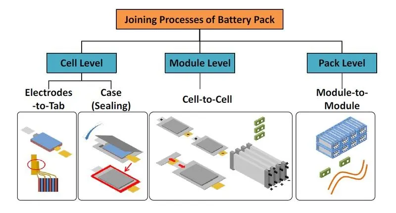
Battery pack constructions are divided into three primary stages of processing: cell level, module level, and pack level constructions.
The electrodes are paired with electrolyte to form various cell types such as cylindrical, prismatic, and pouch cells.
Cells are merged after case sealing to produce module level structure.
These modules are then combined to make pack level constructs.
Joining technologies of cells:
The interconnections between cells/modules are practised by various welding techniques. Some of them are,
- Ultrasonic metal welding.
- Resistance welding.
- Laser beam welding.
- Wire bonding.
- Mechanical Jooining.
Ultrasonic metal welding-
Ultrasonic metal welding (UMW) is a solid-state welding technology that establishes a connection between two metal pieces by applying modest static pressure and an ultrasonic oscillation of roughly 20 kHz. The solid-state weld is generated by inducing continuous shearing and plastic deformation between the pieces while simultaneously eliminating any oxide coatings or impurities.
Most metals may be ultrasonically welded, and the technology is ideal for joining tiny foils, larger sheets with spot or seam welds, and wires.
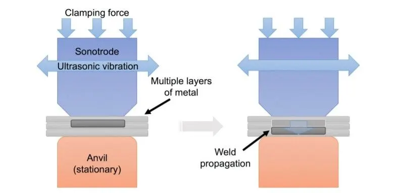
The four types of materials welded in this process can be seen as,
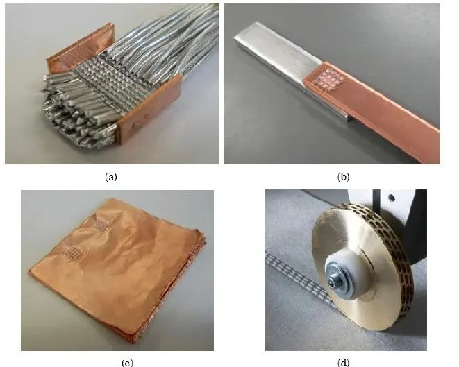
- Aluminium wire welding on copper.
- Copper and aluminium welding.
- Multi-layered copper foil welding.
- Ultrasonic seam welding.
Resistance spot welding-
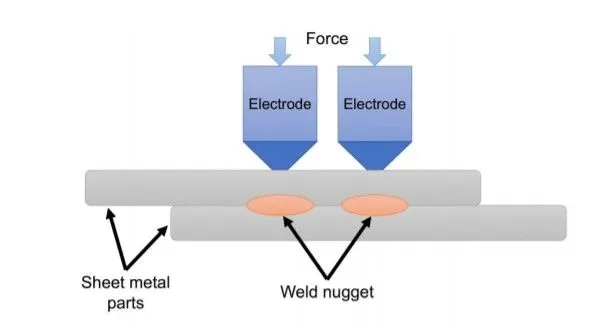
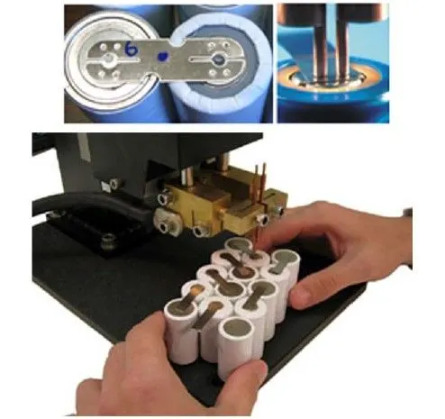
Resistance spot welding is one of the earliest welding techniques (RSW). RSW is a welding process that involves the application of an electrical current and pressure between two electrodes to join two or more metal sheets. Without the introduction of filler material or gases, the electrical resistance of the material at the interface generates heat and melts the materials together.
The temperature rises in the affected area, the contact, until it approaches the melting point of the material. After cooling, a weld nugget develops in the damaged region.
This is a little amount of material that has melted and fused together.
Laser beam welding-
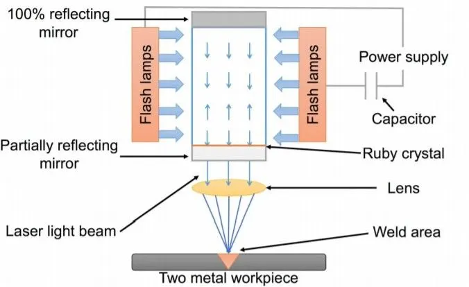
Laser beam welding, often known as LBW, is a welding technology that employs a laser beam to generate a focused heat source that fuses the materials together.
LBW is frequently accomplished utilising keyhole mode welding, in which the metal melts and evaporates because to the high power density of the laser beam.
As metal atoms evaporate from the surface, forces opposing the evaporation generate a local vapour pressure. By lowering the molten metal, the vapour pressure forms a hole known as the keyhole
Here below shown the welding of busbars to cylindrical battery cans.

Enclosures:
Cells in series connection-
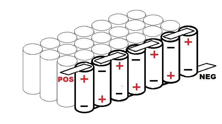
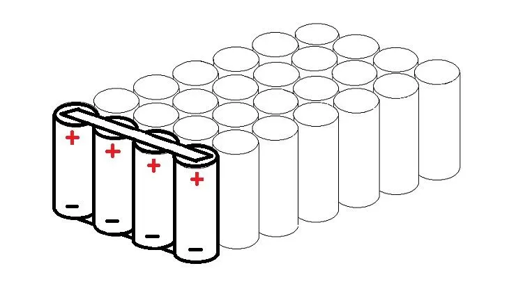
When you link cells in series, you don't change the amps or capacity; you only boost the voltage of the pack. When you link them in series, you connect the positive end of one cell (or P-group) to the negative end of the other, as illustrated below.
Cells in Parallel connections-
If you connect numerous cells with the same sort of electrodes in parallel, they will all behave as if they were one giant cell. Also, when you connect them for the first time, they must be at the same level of charge.
The gap between each cell :
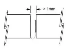
Any mechanical methods should not be used to obstruct the cell vents, which are placed on the end cap(s) of the cells (on the POSITIVE side of the cell). Blocking the cell vent and then sufficiently abusing the cell to build enough pressure prevents the cell from venting correctly. An ESS was designed to be installed end-to-end, with at least 1 mm of gap between cells to allow the vent to open in the event of a malfunction.
Cell holders-
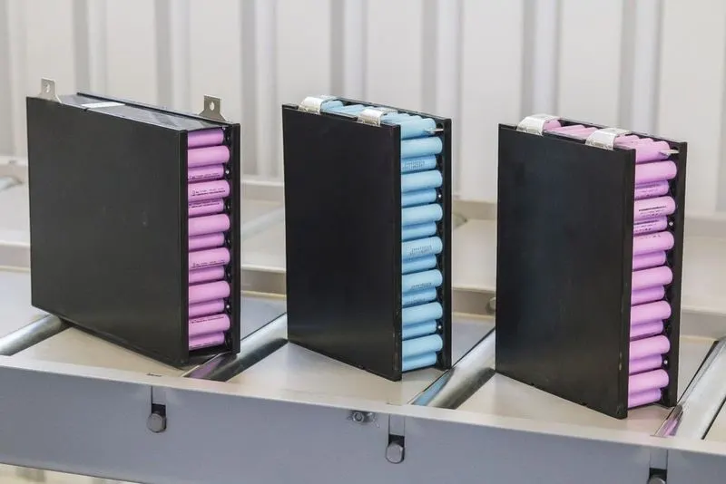
These holders are used to holders the individual cells in a more upright position without mis-assembly. To produce the desired module dimensions, the connections can be made in the appropriate order to form series and parallel connections.

Following the installation of the cells in a single module, the complete maximum positive terminal and maximum negative terminal are produced under a single pair of terminals, as illustrated below.
Here shown the cells are arranged and welded without using cell holders as,
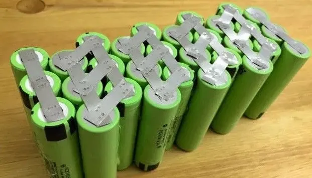
After the linkages are formed, they are simply covered by polimer sheet. Connections with cell holders should be recommended primarily for safety reasons.
Battery Cabinet arrangements-
Each modules are interconnected in series or parllel according to the requirement and packed as a single large cabinet pack as shown below.
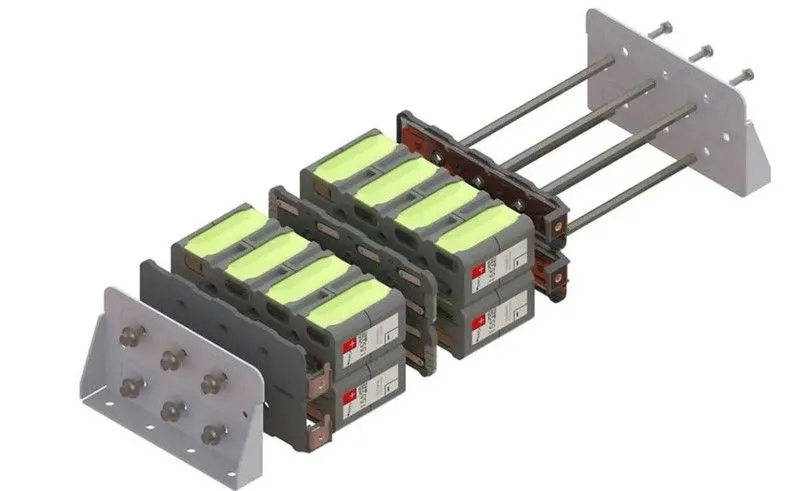
Battery pack arrangement:
Finally the overall battery pack after the arrangement of all cabinet connections with enclosure looks like this as shown below,
The container has vent holes for cooling/heating the battery pack temperature based on the surrounding circumstances.
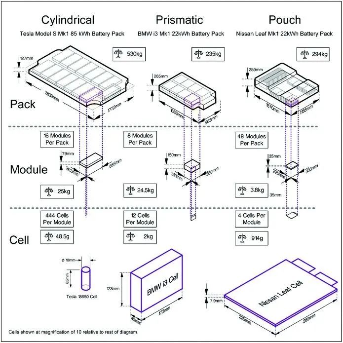
Different EV manufacturers employ various cell types, including as cylindrical, prismatic, and pouch cells.
Every manufacturer has a unique pack structure.
The Tesla, BMW, and Nissan Leaf battery pack construction processes are depicted here.
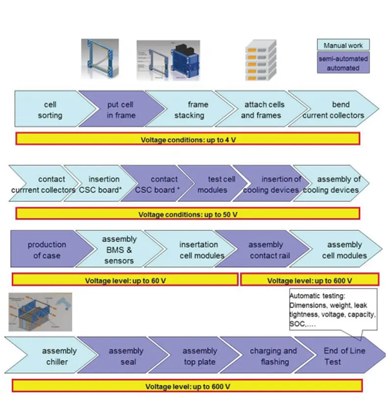
Battery pack production line: