Project 1 - Interfacing a 16*2 LCD with Arduino using I2C protocol
INTERINTEGRATED CIRCUIT (12C) COMMUNICATION PROTOCOL
- 12C/ I2C(Inter-Integrated circuit,eye-squared-C).
- It is a synchronous,multicontroller/multi-target,packet-switched,single-ended,serial communication protocol.
- It is commonly used in short-distance communication protocol.
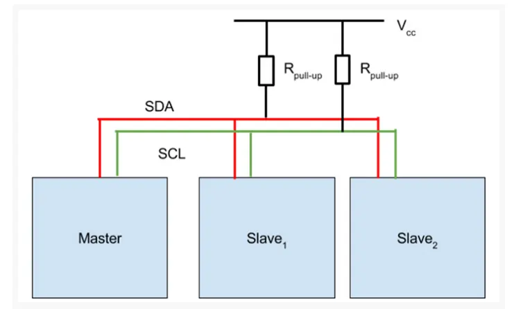
- I2C communication will have 2 lines
SDA(serial data)
SCL(serial clock)
- One master connection and multiple slaves are there.
Advantage
- The ability to connect multiple masters to multiple slaves.
- Simplicity: implementation only requires two wires and some resistors.
Connection diagram
Address and data portions
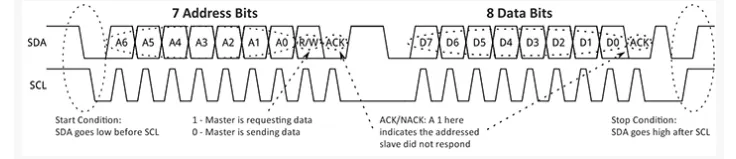
- Depending on each clock we will have a start signal followed by a 7 bit of address .
- One bit for read or write mode.
- If it is read mode,then read the data from 7 bit address.
- If it is write mode,then write the data from 7 bit address.
Arduino
- On the Arduino, I2C implementation occurs through the Wire library (Wire.h).
- The Arduino can be configured as either an I2C master or slave device. On the Arduino Uno, the connections are as follows:
SDA: Analog Pin 4
SCL: Analog Pin 5
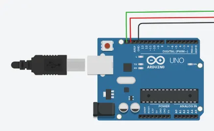
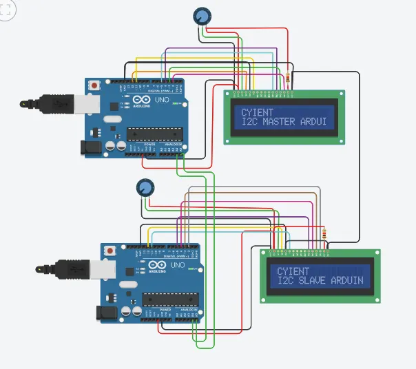
- Green line is the SCL
- Red line is the SDA
Arduino to Arduino 12C communication
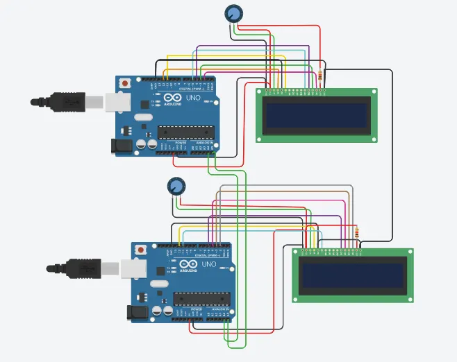
Materials Required:
- Arduino uno(2)
- Potentiometer(2)
- 16*2 LCD(2)
- Resistance(2,1K each)
LCD 16*2
The term LCD stands for liquid crystal display.
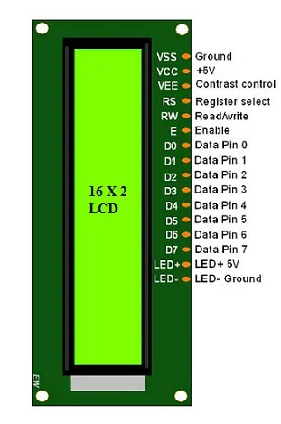
- Pin1 (Ground/Source Pin): This is a GND pin of display, used to connect the GND terminal of the microcontroller unit or power source.
- Pin2 (VCC/Source Pin): This is the voltage supply pin of the display, used to connect the supply pin of the power source.
- Pin3 (V0/VEE/Control Pin): This pin regulates the difference of the display, used to connect a changeable POT that can supply 0 to 5V.
- Pin4 (Register Select/Control Pin): This pin toggles among command or data register, used to connect a microcontroller unit pin and obtains either 0 or 1(0 = data mode, and 1 = command mode).
- Pin5 (Read/Write/Control Pin): This pin toggles the display among the read or writes operation, and it is connected to a microcontroller unit pin to get either 0 or 1 (0 = Write Operation, and 1 = Read Operation).
- Pin 6 (Enable/Control Pin): This pin should be held high to execute Read/Write process, and it is connected to the microcontroller unit & constantly held high.
- Pins 7-14 (Data Pins): These pins are used to send data to the display. These pins are connected in two-wire modes like 4-wire mode and 8-wire mode. In 4-wire mode, only four pins are connected to the microcontroller unit like 0 to 3, whereas in 8-wire mode, 8-pins are connected to microcontroller unit like 0 to 7.
- Pin15 (+ve pin of the LED): This pin is connected to +5V
- Pin 16 (-ve pin of the LED): This pin is connected to GND.
Connection diagram
master code
#include<Wire.h> //Library for I2C Communication functions
#include<LiquidCrystal.h> //Library for LCD display function
LiquidCrystal lcd(12,11,5,4,3,2); //Define LCD Module Pins (RS,EN,D4,D5,D6,D7)
void setup()
{
lcd.begin(16,2); //Initilize LCD display
lcd.setCursor(0,0); //Sets Cursor at first line of Display
lcd.print("CYIENT"); //Prints CIRCUIT DIGEST in LCD
lcd.setCursor(0,1); //Sets Cursor at second line of Display
lcd.print("I2C MASTER ARDUINO"); //Prints I2C ARDUINO in LCD
delay(5000); //Delay for 5 seconds
lcd.clear(); //Clears LCD display
Serial.begin(9600); //Begins Serial Communication at 9600 baud rate
Wire.begin(); //Begins I2C communication at pin (A4,A5)
}
void loop()
{
Wire.requestFrom(8,1); // request 1 byte from slave arduino (8)
byte MasterReceive = Wire.read(); // receive a byte from the slave arduino and store in MasterReceive
int potvalue = analogRead(A0); // Reads analog value from POT (0-5V)
byte MasterSend = map(potvalue,0,1023,0,127); //Convert digital value (0 to 1023) to (0 to 127)
Wire.beginTransmission(8); // start transmit to slave arduino (8)
Wire.write(MasterSend); // sends one byte converted POT value to slave
Wire.endTransmission(); // stop transmitting
lcd.setCursor(0,0); //Sets Currsor at line one of LCD
lcd.print(">> Master <<"); //Prints >> Master << at LCD
lcd.setCursor(0,1); //Sets Cursor at line two of LCD
lcd.print("SlaveVal:"); //Prints SlaveVal: in LCD
lcd.print(MasterReceive); //Prints MasterReceive in LCD received from Slave
Serial.println("Master Received From Slave"); //Prints in Serial Monitor
Serial.println(MasterReceive);
delay(500);
lcd.clear();
}
slave code
#include<Wire.h> //Library for I2C Communication functions
#include<LiquidCrystal.h> //Library for LCD display function
LiquidCrystal lcd(12,11,5,4,3,2); //Define LCD Module Pins (RS,EN,D4,D5,D6,D7)
byte SlaveReceived = 0;
void setup()
{
lcd.begin(16,2); //Initilize LCD display
lcd.setCursor(0,0); //Sets Cursor at first line of Display
lcd.print("CYIENT"); //Prints CIRCUIT DIGEST in LCD
lcd.setCursor(0,1); //Sets Cursor at second line of Display
lcd.print("I2C SLAVE ARDUINO"); //Prints I2C ARDUINO in LCD
delay(5000); //Delay for 5 seconds
lcd.clear(); //Clears LCD display
Serial.begin(9600); //Begins Serial Communication at 9600 baud rate
Wire.begin(8); //Begins I2C communication with Slave Address as 8 at pin (A4,A5)
Wire.onReceive(receiveEvent); //Function call when Slave receives value from master
}
void loop(void)
{
lcd.setCursor(0,0); //Sets Currsor at line one of LCD
lcd.print(">> Slave <<"); //Prints >> Slave << at LCD
lcd.setCursor(0,1); //Sets Cursor at line two of LCD
lcd.print("MasterVal:"); //Prints MasterVal: in LCD
lcd.print(SlaveReceived); //Prints SlaveReceived value in LCD received from Master
Serial.println("Slave Received From Master:"); //Prints in Serial Monitor
Serial.println(SlaveReceived);
delay(500);
lcd.clear();
}
void receiveEvent (int howMany) //This Function is called when Slave receives value from master
{
SlaveReceived = Wire.read(); //Used to read value received from master and store in variable SlaveReceived
}
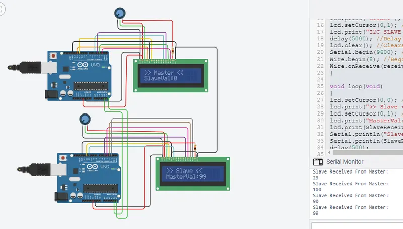
output