Project 1 - Implement a fully functional Queue in C language using Linked lists
NOTE: Please refer to the below attached PDF for better readability
Project 1 - Implement a fully functional Queue in C language using Linked lists
An IMU has two sensors:
Accelerometer
Gyroscope
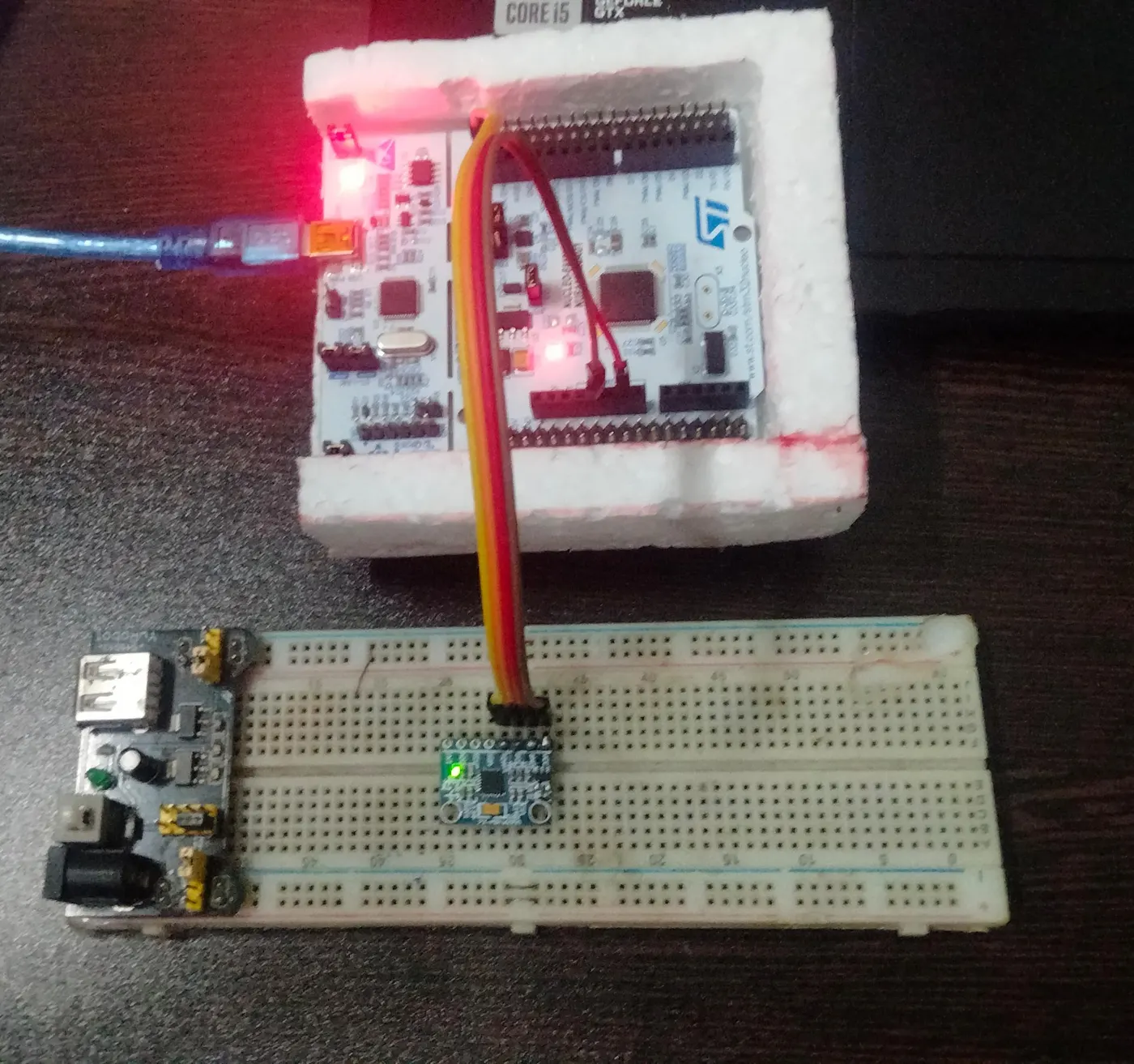
Integrate the IMU to the development board; classify the data coming from the Accelerometer and Gyroscope. Send the data of respective sensors on “Separate Queues” to a particular task. This task will identify which source is sending the data using “Queue Sets” and transfer the data to the respective UART Channel.
Aim:
To integrate an Inertial Measurement Unit (IMU) with a microcontroller and classify data coming from the accelerometer and gyroscope. The goal is to send the respective sensor data to separate queues and use a dedicated task to identify the data source using Queue Sets. Finally, the project transfers the data to the appropriate UART channel for monitoring and analysis.
Tools and components Used:
<!-- [if !supportLists]-->1. <!--[endif]-->STM32CubeIDE for writing and compiling the code,
<!-- [if !supportLists]-->2. <!--[endif]-->STM32CubeMX for configuring the microcontroller peripherals, and
<!-- [if !supportLists]-->3. <!--[endif]-->Hercules for monitoring the UART output,
<!-- [if !supportLists]-->4. <!--[endif]-->STM32F446RE Nucleo64 Board,
<!-- [if !supportLists]-->5. <!--[endif]-->MPU6050 Sensor module.
Theory:
IMU Implementation with MPU6050 Sensor Module
An Inertial Measurement Unit (IMU) combines multiple sensors to measure and report specific non-gravitational acceleration, rotational rate, and, in some cases, magnetic field information. In this project, the MPU6050 sensor module is employed, featuring both an accelerometer and a gyroscope. The MPU6050 is interfaced with the STM32 microcontroller through I2C communication.
The "TJ_MPU6050.h" initializes the MPU6050 module, and configures the accelerometer and gyroscope parameters. The data acquisition task “(DataAcquisitionTask)” reads scaled accelerometer and gyroscope data from the MPU6050 and sends it to separate queues “(accelQueue and gyroQueue)”. The data processing task “(DataProcessingTask)” waits for data in a Queue Set “(queueSet)” and identifies the source using “xQueueSelectFromSet”. It then processes and sends the data to the UART channel.
Code:
Note: this is part of the code please refer to below attached ZIP file for the complete code
void DataAcquisitionTask(void *pvParameters)
{
while (1){
// Acquire accelerometer data
MPU6050_Get_Accel_Scale(&myAccelScaled);
xQueueSend(accelQueue, &myAccelScaled, portMAX_DELAY);
// Log accelerometer data
char accelMsg[150];
snprintf(accelMsg, sizeof(accelMsg), "[%lu] Sent Accelerometer: X= %f, Y= %f, Z= %f\r\n", accelSequenceNumber++, myAccelScaled.x, myAccelScaled.y, myAccelScaled.z);
HAL_UART_Transmit(&huart2, (uint8_t *)accelMsg, strlen(accelMsg), HAL_MAX_DELAY);
HAL_GPIO_WritePin(GPIOA, GPIO_PIN_5, GPIO_PIN_SET);
// Delay for a short period
vTaskDelay(pdMS_TO_TICKS(300));
// Acquire gyroscope data
MPU6050_Get_Gyro_Scale(&myGyroScaled);
xQueueSend(gyroQueue, &myGyroScaled, portMAX_DELAY);
// Log gyroscope data
char gyroMsg[150];
snprintf(gyroMsg, sizeof(gyroMsg), "[%lu] Sent Gyroscope: X= %f, Y= %f, Z= %f\r\n", gyroSequenceNumber++, myGyroScaled.x, myGyroScaled.y, myGyroScaled.z);
HAL_UART_Transmit(&huart2, (uint8_t *)gyroMsg, strlen(gyroMsg), HAL_MAX_DELAY);
HAL_GPIO_WritePin(GPIOA, GPIO_PIN_5, GPIO_PIN_RESET);
// Delay for a short period
vTaskDelay(pdMS_TO_TICKS(300));
}
}
void DataProcessingTask(void *pvParameters)
{
QueueHandle_t activeQueue;
ScaledData_Def data;
while (1){
// Wait for data in the Queue Set
activeQueue = xQueueSelectFromSet(queueSet, portMAX_DELAY);
if ((activeQueue == accelQueue) || (activeQueue == gyroQueue))
{
// Data from accelerometer queue
xQueueReceive(accelQueue, &data, 0); // Receive data with zero delay
// Process and send data to UART for accelerometer
char accelMsg[150];
snprintf(accelMsg, sizeof(accelMsg), "[%lu] Received Accelerometer: X= %f, Y= %f, Z= %f\r\n", accelSequenceNumber++, data.x, data.y, data.z);
HAL_UART_Transmit(&huart2, (uint8_t *)accelMsg, strlen(accelMsg), HAL_MAX_DELAY);
vTaskDelay(pdMS_TO_TICKS(300));
// Data from gyroscope queue
xQueueReceive(gyroQueue, &data, 0); // Receive data with zero delay
// Process and send data to UART for gyroscope
char gyroMsg[150];
snprintf(gyroMsg, sizeof(gyroMsg), "[%lu] Received Gyroscope: X= %f, Y= %f, Z= %f\r\n", gyroSequenceNumber++, data.x, data.y, data.z);
HAL_UART_Transmit(&huart2, (uint8_t *)gyroMsg, strlen(gyroMsg), HAL_MAX_DELAY);
vTaskDelay(pdMS_TO_TICKS(300));
}
}
}
CODE EXPLANATION:
<!-- [if !supportLists]-->Ø <!--[endif]-->The DataAcquisitionTask acquires scaled accelerometer and gyroscope data, sends it to separate queues, logs the data to UART, and toggles a GPIO pin. The DataProcessingTask waits for data in the Queue Set, identifies the source, processes the data, and transmits it to UART.
 |
Conclusion:
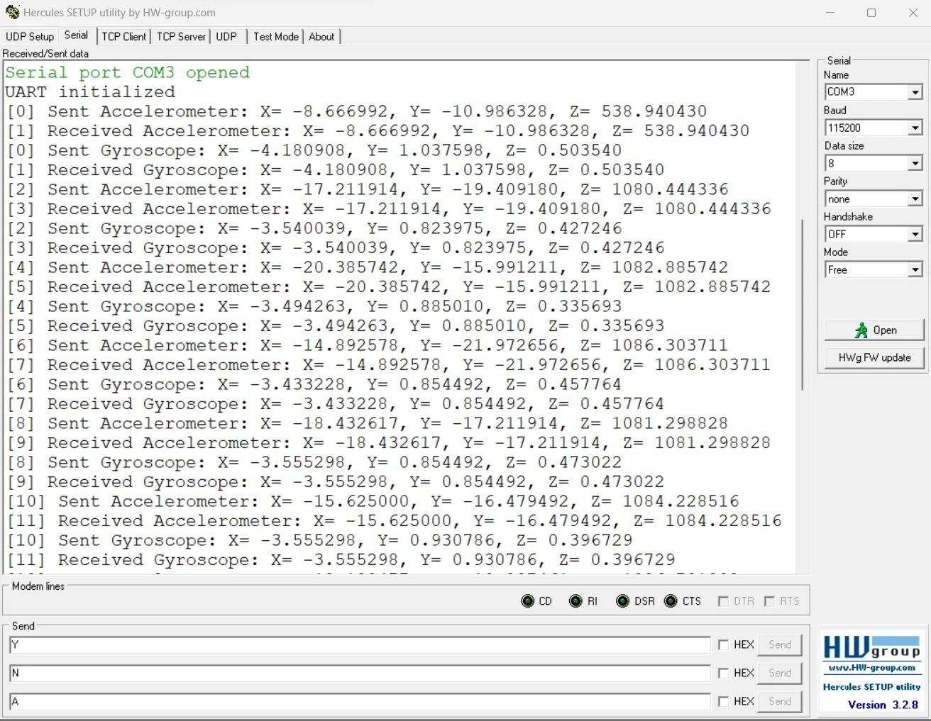
The project successfully demonstrates the integration of an IMU with a microcontroller, specifically using the MPU6050 sensor module. It showcases effective data classification, queue usage, and task synchronization for managing data from multiple sensors in a real-time system.
 |
RESULT:
The implementation effectively classifies and processes data from the accelerometer and gyroscope, transmitting it to separate UART channels for monitoring. The use of FreeRTOS features such as queues and Queue Sets ensures efficient task management and synchronization. The project provides a foundation for integrating IMU data into embedded systems for various applications.
KEY leanings:
The project provides a practical example of integrating sensors, specifically an Inertial Measurement Unit (IMU) with an accelerometer and gyroscope, into a FreeRTOS-based embedded system. The key learnings from this project include:
<!-- [if !supportLists]-->1. <!--[endif]-->Multitasking with FreeRTOS:
<!-- [if !supportLists]-->l <!--[endif]-->Understanding and implementing multitasking with FreeRTOS, as evidenced by the creation and management of two tasks (DataAcquisitionTask and DataProcessingTask).
<!-- [if !supportLists]-->l <!--[endif]-->Effective use of task priorities to control the execution order of tasks.
<!-- [if !supportLists]-->2. <!--[endif]-->Inter-Task Communication with Queues:
<!-- [if !supportLists]-->l <!--[endif]-->Implementation of inter-task communication using queues (accelQueue and gyroQueue) to transfer data between the data acquisition and data processing tasks.
<!-- [if !supportLists]-->l <!--[endif]-->Proper utilization of queues for synchronizing data flow between tasks.
<!-- [if !supportLists]-->3. <!--[endif]-->Queue Sets for Source Identification:
<!-- [if !supportLists]-->l <!--[endif]-->Introduction to Queue Sets (queueSet) for efficiently waiting on multiple queues and identifying the source of incoming data.
<!-- [if !supportLists]-->l <!--[endif]-->Utilization of Queue Sets to streamline the selection of the active queue and subsequent data processing based on the source.
<!-- [if !supportLists]-->4. <!--[endif]-->Sensor Integration - MPU6050:
<!-- [if !supportLists]-->l <!--[endif]-->Configuring and utilizing a sensor module (MPU6050) with both accelerometer and gyroscope functionalities.
<!-- [if !supportLists]-->l <!--[endif]-->Interfacing with the sensor through I2C communication for acquiring raw sensor data.
<!-- [if !supportLists]-->5. <!--[endif]-->UART Communication:
<!-- [if !supportLists]-->l <!--[endif]-->Configuring and using UART for serial communication, allowing data transmission to an external interface (e.g., a computer or another microcontroller).
<!-- [if !supportLists]-->l <!--[endif]-->Utilization of UART for logging and transmitting sensor data.
<!-- [if !supportLists]-->6. <!--[endif]-->Error Handling in Embedded Systems:
<!-- [if !supportLists]-->l <!--[endif]-->Implementation of basic error handling using the Error_Handler function in case of critical failures.
<!-- [if !supportLists]-->l <!--[endif]-->Acknowledgment and handling of potential errors during the initialization of peripherals and sensors.
<!-- [if !supportLists]-->7. <!--[endif]-->System Clock Configuration:
<!-- [if !supportLists]-->l <!--[endif]-->Configuration of the system clock, including setting up the PLL, HSE, and other clock-related parameters for the “microcontroller”.
<!-- [if !supportLists]-->8. <!--[endif]-->Practical Implementation of Real-time Systems:
<!-- [if !supportLists]-->l <!--[endif]-->Experience in designing and implementing a real-time system that acquires sensor data and processes it in a timely manner.
<!-- [if !supportLists]-->9. <!--[endif]-->Task Synchronization and Timing:
<!-- [if !supportLists]-->l <!--[endif]-->Usage of task delays (vTaskDelay) to control the timing between sensor readings and data processing.
These key learnings provide a foundation for developing embedded systems that involve sensor integration, real-time processing, and multitasking capabilities. The project demonstrates how to efficiently manage and process data from multiple sources in a real-time environment.
Drive link for documents:
https://drive.google.com/drive/folders/1hULcZ_CHRFdBo4thDJ7pzZsdPS2g5R6w?usp=sharing