Project 1 - Geometric Design Parameter- Prerequisites
Q1. List all the highway elements required for Road Geometric Design as prerequisite & necessary checklist during design. eg. Design Speed, Design Vehicle etc.
- Cross Section Element
- Sight Distance
- Horizontal Alignment details
- Vertical Alignment details
- Intersectional details
- Cross Section Element :-
- Pavement Surface Characteristics
- Cross-Slope / camber
- Width of pavement or Carriageway
- Divider/Medians/Traffic saparators
- Kerb
- Shoulder
- Road Margin
- Road / width of formation
- Road Land / Right of way
- Pavement Surface Characteristics : -
Pavement surface chracteristics depends upon pavement type, which in turn depends on availability of material, cost, composition of construction available.
surface chracteristics includes,
- Skid and Slip
- Friction
- Unevenness index
- Light Reflecting characteristics
- Drainage
- Skid and Slip : -
Skidding tae place when there longitudinal movement of wheel is more than rotational movement during the break.
To avoid skidding, friction resistance must be greater than the breaking force.
Slipping occurs hen wheel revolves more thwn the coresponding longitudinal movement along the roads during acceleration (R.M > T.M).
It is generally occurs on pavement surface which is either slipping & wet the road surface is with mud.
For pure slip, Rotational movement = 0, Translation moment =0
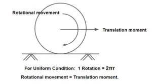
Skid and Slip
- Friction
It decide the operating speed and Minimum distance required for stopping the vehicle.
Maximum friction is developed when break are applied up to complete extent.
Friction also governs rotational transitional moment of the wheel.
It is further classified into two:
- Longitudinal friction
- Lateral or Transverse friction
(A) Longitudinal friction:
-
Longitudinal friction help in support movement of vehicle.
-
Longitudinal friction depends upon speed, For high speed friction is less.
(B) Lateral or Transverse friction:
-
Lateral friction come in picture only when there is a lateral force on vehicle.
| Rotational movement | Translation moment | Impact | |
| Longitudinal friction is Increased | Decrease | Increased | Tyre burning |
| Longitudinal friction is Decrease | Increased | Decrease | No moment of vehicle |
- Longitudinal friction
- Unevenness Index:
Presence of undulations on the Pavement surface is called Unevenness.
Unevenness index is defined as cumulative undulation per kilometre road length.
It is expressed in terms of mm/Km.
It is measured by BUMP INTEGRATOR.(Developed by CRRI)
Uneven surface increases riding discomfort, fuel consumption, wear and tear of tyres and other part and accidents.
The different values of Unevenness Index and the corresponding serviceability of road is as follows:
Unevenness Index Type of Road < 1500 Good 1500 - 2500 satisfactry 2500 - 3500 Bad >3500 Uncomfortable
Quality Of Pavement Note- Internationally Roughness is measured in term of IRC ( IRC=INTERNATIONAL ROUGHNESS INDEX).
BI=630(IRI)1.12
BI = BUMP INTEGRATOR (mm/km)
IRC=INTERNATIONAL ROUGHNESS INDEX (m/km)
Unevenness of the pavement depends upon following factors.
-
Improper Compaction.
-
Use of improper construction method.
-
Use of interior quality material.
-
Improper surface and sub surface drainage.
-
Poor maintenance of pavement surface.
-
-
Light Reflecting characteristics :-
Visibility over the pavement surfaces depend upon its color and light characteristics.
The glare cases by the reflection of the headlight is high on wet pavement surface than dry pavement.
Light colored pavement surface give good visibility at night but produce more glare during the day light while on the other hand black too pavement poor visibility in night.
- Drainage :-
Pavement must be completely impermeable so that seepage of water into the pavement layers does not take place and the geometrical pavement surface should be such that which helps and remains out of the water from the surface quickly.
- Cross-Slope / camber : -
- It is the slope provide to the road surface in the transverse direction to drain the rainwater from the road surface to avoid the following:
- Stripping of bitumen from the aggregate in the presence of the water.
- In order to avoid swelling of sub grade in case water seeps up to it.
- The slipping of the vehicle over the wet pavement.
- Glare over the wet pavement surface.
- On straight Road it is provide by raising the center of carriage way with respect to edges forming the crown on the highest point along the center line.
- At horizontal curve with super elevation, the surface drainage is provided by raising the outer edge.
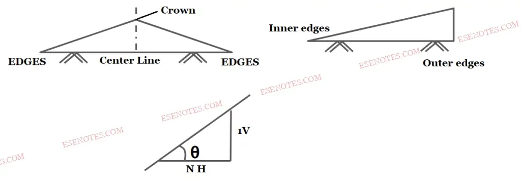
Cross Section Of Camber - It is represented in any of the following ways:
- As percentage :For example cross-section 5% ⇒ tanθ = 5100.
- As fraction : For example cross- section = 1 in 20 = 120 = 0.05.
- The value of cross-section depend on following factor:
- Type a pavement surface
- Amount of rainfall
- It is represented in any of the following ways:
| Road Surface type | Heavy Rain Fall | Light Rain Fall |
| Cement Concrete or High Bituminius surface | 2% | 1.7% |
| Thin Bituminious surface | 2.5% | 2% |
| WBM /Gravel pavement | 3% | 2.5% |
| Earthen Road | 3.5% | 3% |
Camber for Different road surfce
Type of Cross- Slope / Camber
Straight line Cαmber
Parabolic Cαmber
Composite Cαmber
- Width of pavement or Carriageway : -
Width of payment depends upon width of traffic, lane and number of lanes.
Width of traffic lane is decided on the basic the type of vehicle moving on it, along with same clearance in both the sides.
Passenger car is considered as a standard vehicle to decide the width of carriageways. (Width of passenger car = 2.44 meter= 2.5 meter)
For rural highway, if pavement has two or more lane, width of single lane is 3.5 meter.
The number of lane to be provided depends upon traffic volume.
| Type of Road | Width of Carriage Way |
| Single Lane Road | 3.75 M |
| Two Lane without Raised Kerb | 7.0 M |
| Two Lane with Raised Kerb | 7.5 M |
| Intermediate Carrige way | 5.5 M |
| Multilane pavement | 3.5m per Lane |
- Divider/Medians/Traffic saparators : -
- Divider is an element provided to Road along the center line to separate two way traffic. The main function of median is to prevent “Head on collision” between vehicles moving in the opposite direction. it also serves following other functions:
- To channelize traffic into the streams.
- To protect the pedestrians.
- Glaring effect due to Head light of the opposite direction vehicle can be reduced.
- To segregate the slow traffic.
- Medians can be provided in following forms:
- As pavement marking
- Physical dividers (Mechanical separator)
Low or Mountable type Kerb : - Height of this type of kerb is about 10 cm with a slope or batter to help the vehicle climb the kerb easily.
Semi- Barrier type Kerb : - Height of this type of Kerb is about 15 cm with a batter of 1:1 on the top 7.5 cm. It is provided where pedestrian traffic is high.( Pedestrian = A person who is walking in the street.)
Barrier type kerb : -
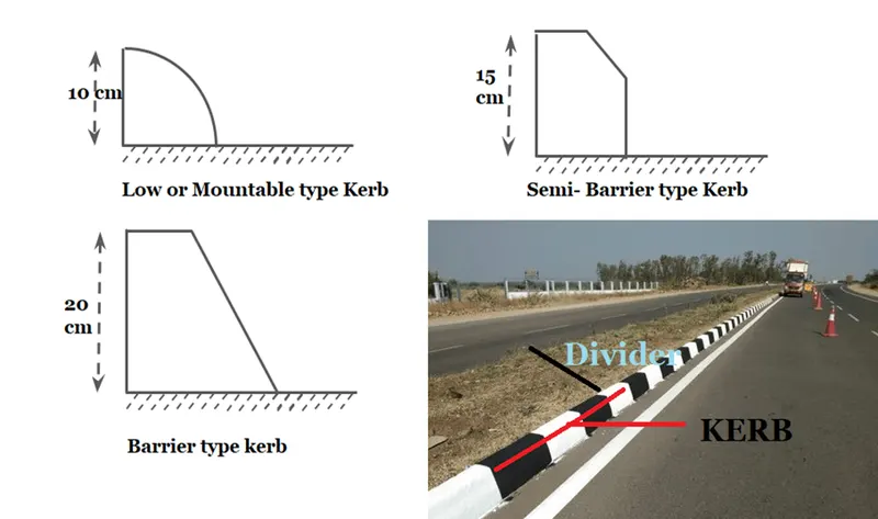
Friction of Kerb :-
To facilitate and control drainage.
To delineate the pavement edge.
To present a more finished appearance.
To strengthen and produce the pavement edge
Shoulder : -
means the area within the Road Layout that lies four (4') feet to either side of the paved portion of the Road Layout; provided, however, that if no portion of the Road Layout is paved, then "Road Shoulder" shall mean the area lying four (4') to either side of the traveled way portion of the Road Layout
Extra width provided adjacent to edge of pavement is called shoulder.
It is provided for emergency point of view like Breakdown of vehicle, medical emergency etc
As per IRC
Minimum width of shoulder required for a highway is 2.5 meter.
Cross slope of shoulder should be 0.5% more than cross slope of adjoining pavement, having minimum value of 3% & maximum value of 5%.
5% ⊀ cross slope(shoulder)= (0.5%+ cs of pavement) ⊀3%
Road Margin : -
These are the areas which are not used as regular roadways. The various elements include in the road margins are as follows:
Parking lane : These are generally provided on an urban road to allow car parking. Parallel parking is generally provided for safe moving of vehicles. However angle parking is also provided. Parking lane should have sufficient width. For parallel parking 3.0 m width is required.
Lay Bye : These are provided near public convenience to avoid the conflict with a running traffic minimum width is 3 meter.
Cycle Track : These are provided in urban areas for the safe movement of cycle traffic. The minimum width required is 2 meter for the cycle track and it can be increased by 1 m for each additional cycle lane.
Drive way : these are used to connect the highway with commercial establishments like fuel stations, service-station etc.
Footpath : These are providing urban roads having heavy vehicular as well as pedestrian traffic, to provide the protection to pedestrians. Minimum width of footpath should be 1.5 m and it may increase based on the pedestrian traffic volume.
Guard Rail : These are provided at the edge of shoulder when the road conditions on fill to prevent vehicles from running off the embankment. Guard stones are installed at a suitable distance to provide better night visibility on the curves under headlights of the vehicle.
Service Road : These are provided parallel to the highway and isolated by a separator and access to highways provided only at selected points. They are provided to avoid congestion on the highway and expressway.
Bus Bays : It may be provide by recessing the kerb to avoid the conflict with the moving traffic and must be located at least 75m away from the intersection. It is used for safe plying of Passenger and Cargo from Bus.
Road / width of formation : -
It is the sum of with pavement or carriageway including separator (if any) and the shoulder.
Roadways width is the top of highway embankment or bottom width of highway cutting excluding the side drain.
Width of Formation of various class of Road are as follows:
| Road Classification | Lane | Road Width (M) | |
| Plan & Rolling Terrian | Mountainous or steep terrian | ||
| National or State highway | Single Lane | 12 | 6.25 |
| Two Lane | 12 | 8.8 | |
| Major Distric Road | Single Lane | 9 | 4.75 |
| Two Lane | 9 | - | |
| Other Distric Road | Single Lane | 7.5 | 4.75 |
| Two Lane | 9 | - | |
| Village Road - Single Lane | Single Lane | 7.5 | 4 |
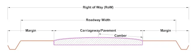
Road Land / Right of way : -
It is the area of the land acquired for the road along its alignment keeping In view it’s future expansion also.
Construction of a particular type of a building is only permitted with sufficient set back from the road boundary up to Central line.
Width of land for different road in rural areas or as follows
| Classification of Roads | Road Land / Right of way | |||
| Plan & Rolling Terrian | Mountainous or steep terrian | |||
| Open area | Builtup area | Open area | Builtup area | |
| Express way | 90 | - | 60 | - |
| National or State highway | 45 | 30 | 24 | 20 |
| Major Distric Road | 25 | 20 | 18 | 15 |
| Other Distric Road | 15 | 15 | 15 | 12 |
| Village Road - Single Lane | 12 | 10 | 9 | 9 |
Width of Road Land or Right of Way
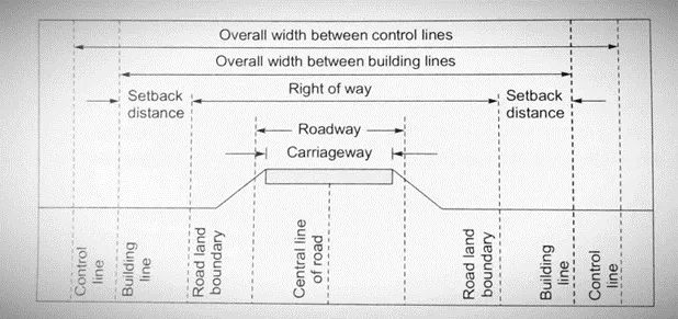
Right of Way
Sight Distance : -
Sight distance is the length of road visual a head to the driver at any distance. ( it is considered by taking the height of eyes of the driver to be 1.2 m and height of object to be 0.15 m)
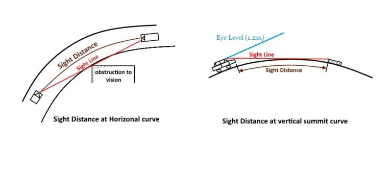
Sight distance on curve
Restriction to the visibility/sight distance maybe caused in the following cases:
At horizontal curve, when the line of sight is obstructed by the object and the inner side of the curve.
At a vertical curve the line of sight age of obstructed by the road surface of the curve.
At an uncontrolled intersection when a driver from one of the approach road is able to sight a vehicle from another approach road towards it at the intersection, due to the presence of obstruction.
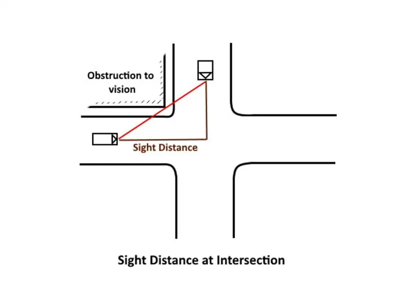
The sight distance available to the driver is depend upon following factor:
Feature of road ahead: Horizontal curve, vertical profile, traffic condition, position of obstruction.
Height of driver eyes above the road surface.
Height of object above the road surface
The sight distance available to the driver is depend upon following factor : -
Total Reaction Time of Driver
Design speed
Braking Efficiency
Frictional Resistance Between Road and Tyres
Gradient of Road
Total Reaction Time of Driver
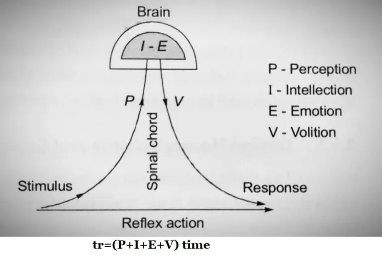
It is the time taken from the instant the object is visible to the driver to the instant brakes and apply effectively.
The total reaction time is further divided into different components and can be explained as follows:
Perception(P): The time required for the sensation received by the eyes or ears of a driver to be transmitted to the brain through the nervous system and spinal cord.
Intellection Time (I): it is the time required to the driver to under stand the situation. It is also the time required for comparing different thoughts, regrouping & registering new sensation.
Emotion Time (E): It is the time elapsed during emotional sensations and other mental disturbances such as fear, anger, superstition etc with the situation to come into play.This time varies from person to person and even for the same person in different situations .
Volition Time (V): It is the time taken by a driver, for final action, like application of brakes.
The above can be termed as “PIEV” analysis for Total Reactions Time.
Design Speed : -
During the total reaction time of the driver the distance moved by the vehicle is depend upon design speed.
If speed of vehicle is not mentioned in the problem then consider the design speed of the highway as the speed of vehicle.
Braking distance means distance traveled by vehicle before coming to a stop/half also depends on design speed.
Braking Efficiency : -
Efficiency of brakes depends upon the age and characteristics of the vehicle. If we say the brakes are 100% efficient, it means the vehicle will stop at the moment of application of brakes. But practically 100% efficiency update is not achieved, otherwise skidding will occur which is uncontrollable and dangerous for the vehicle and road users.
For the design purpose of the highway, we considered 50% brake efficiency of the vehicle.
Frictional Resistance Between Road and Tyres : -
The frictional resistance developed between the road and tyres depends on the coefficient of friction.
Higher is coefficient of friction, higher is the frictional resistance and lower is SSD.
Coefficient of friction further depends upon the condition of tyres and Road.
It is further linked with the design speed of vehicle as follows:
| Speed (Km) | 20-30 | 40 | 60 | 65 | 80 | 100 & Above |
| Longitudinal frictional for SSD | 0.4 | 0.38 | 0.37 | 0.36 | 0.35 | 0.35 |
Gradient of Road :-
When we are going down on a gradient, gravitational force also come into action which causes the vehicle to take more time to stop the vehicle means more sight distance is required. While in climbing up a gradient less sight distance is required because the time taken to stop the vehicle will be less.
Sight distance following types : -
Stopping sight distance (SSD).
Safe overtaking distance (OSD).
Intermediate sight distance (ISD)
Safe sight distance for entering into uncontrolled intersection.
Headlight sight distance.
Stopping sight distance (SSD) : -
The minimum distance visible to a driver ahead to safety stop a vehicle travelling at design speed without collision with any other obstruction is termed as “SSD”. It is also termed as “Absolute Minimum Sight Distance” or ” Non-Passing Sight Passing”.
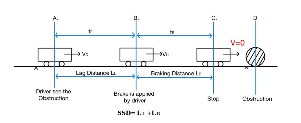
The stopping distance of vehicle include:
- Lag Distance (LL)
- Braking Distance(LB)
- Lag Distance (LL)
- The distance travelled by vehicle at uniform design speed during the total reaction time (tr) termed as “Lag Distance (LL).
V= Design Speed(m/sec).
LL=V×tr
tr= Reaction time(sec).
LL= Lag Distance(m).
LL=(V×10^3)/(60×60)×tr.
LL=(10^3)/(3600V)×tr.
LL=(5/18)V×tr.
LL=0.278×V×tr
V (km/hours).
tr (sec).
tr = 2-4 (sec).
As per IRC reaction time is taken to be 2.5 second for SSD.
Braking Distance(LB) : -
- The distance travelled by the vehicle after the application of brake, termed as Braking Distance(LB).
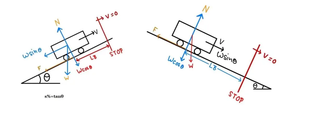
SSD BRAKING DISTANCE
Case-1: Ascending Gradient:→
Gradient= tanθ= s100= s%
F = Friction ForceΔK·E= Work Done (Work Done= Force× Distance)
0-12mV²= –LB(mg·sinθ+f×mg·cosθ)
if θ is very smallsinθ≈ tanθ
LB=V^2/2g(f+s%)
LB in meter.
V in metre/second.
g in metre/second²
Case-2: Decending Gradient:→
LB=(V^2)/254(f−s%)
Case-3: Flat Road:→
LB=(V^2)/(254xf) s=0SSD=LL+LB
SSD=0.278×V×tr+ V2254(f±s%)
SSD= Stopping Sight Distance (meter)
V= Design Speed(m/sec)
tr= Reaction time(sec)
f= Friction Coefficient(unit less)
s= Gradient
Note:
- SSD must be available at each & every section of the road.
- As the SSD, required on descending gradient is higher, it is necessary to determine the critical value of SSD for the descending gradient on the roads with gradient & for two way traffic flow.
- On the restricted width or on single lane roads when two way movement of traffic is permitted, the minimum SSD equal to twice the SSD to enable both the vehicle coming from opposite side to stop.(For single lane road,two way traffic)
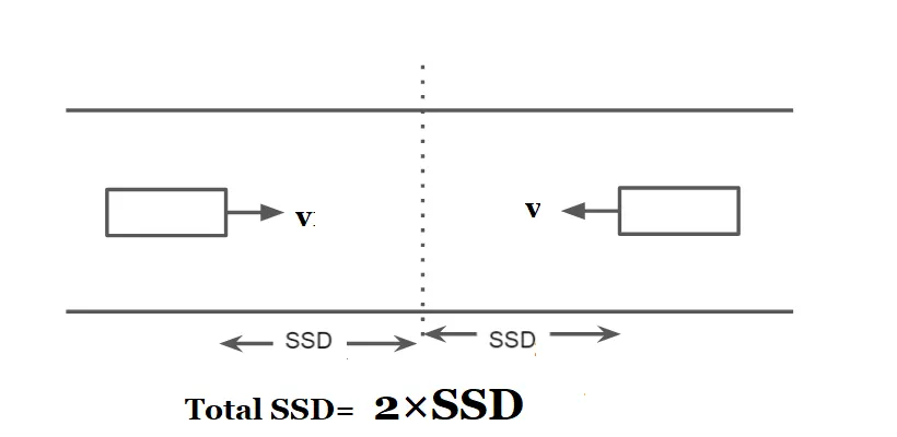
- If SSD can not be provided on any stretch of road due to unavoidable reason for the design speed available, the speed should be restricted either by installing speed- limit regulation signs or by forced reduction of the speed.
- This is however temporary, and efforts must be made to provide SSD over the period of time. (By the changing alignment of road or by removing the obstruction.)
- The SSD recommended by IRC are as follows:
| Design Speed (Km/h) | 20 | 25 | 30 | 40 | 50 | 60 | 65 | 80 | 100 |
| SSD (M) | 20 | 25 | 30 | 45 | 60 | 80 | 90 | 120 | 180 |
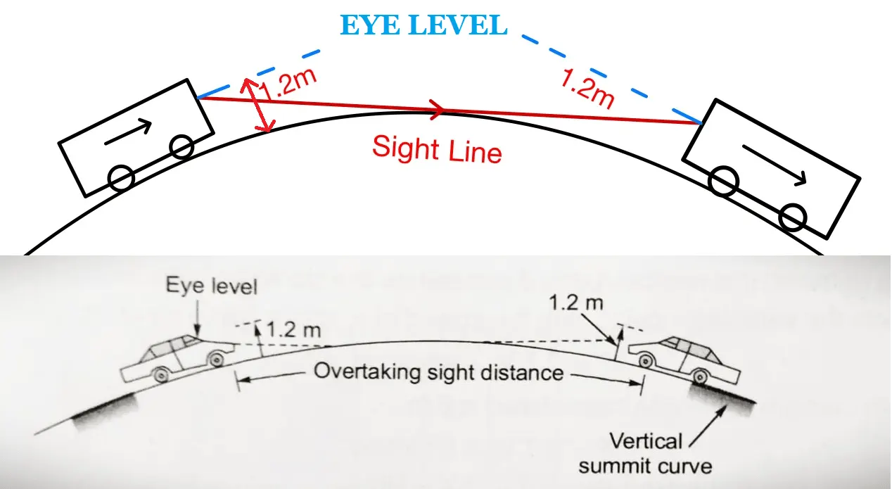
Factors effecting OSD
- Speed of vehicle , Overtaking vehicle, Overtaken vehicle, The vehicle coming from the opposite direction.
- Reaction time and skill of driver.
- Gradient of Road.
- Condition of overtaken vehicle which governs the rate acceleration.
- Distance between the two vehicle.
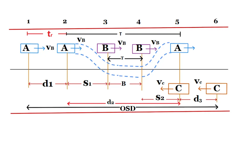
Overtaking Manoeuvre
The overtaking moment maybe split up into three operation as follows:
- d1:- It is the distance travelled by overtaking vehicle “A” during that reaction time “tr” of the driver, before starting to overtake vehicle B at speed of VB.
- d2:- it is the distance travelled by vehicle “A”during the actual overtaking operation of time “T”.
- d3:- It is the distance travelled by an oncoming vehicle “C” during the actual overtaking operation of a for time “T”.
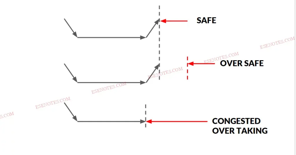
Assumption in analysis of OSD
- Overtaking vehicle is forced to reduce speed up to the speed of overtaken vehicle for reaction time.
- When the driver of vehicle “A” find sufficient clear gap, decide within a reaction time to overtake.
- The vehicle “A” accelerated and overtakes the vehicle “B” within a distance d2 during the time “T”.
- The distance d2 is split in components.
- During this overtaking time “T” the vehicle “C” coming from opposite direction travel through distance d3.
case.1
|
d1= vb·tr (m) |
vb (m/sec)= speed of the slow moving vehicle, tr = Reaction Time (2 sec). |
|
d1= 0.278vb·tr (m) |
vb (km/hr) |
As per IRC reaction time is taken to be 2.0 second for OSD.
case.2
d2= s1+s2+B.
s1 or s2= minimum spacing between the two vehicle, which depends upon their speed. It is also termed as space headway. but for design s1=s2=s (s1+s2= 2s).
d2= 2s +B.
Space Headways
|
s = (0.7×vb +6) m. |
vB put in metre/second. |
|
s= (0.7×0.278×vb +6) m. |
|
|
s= (0.2×vb +6) m. |
vB put in kilometre/hours. |
| B= Distance traveled by vehicle ‘B’ of speed vb and time ‘T’. | |
|
B= vb·T (metre) |
vB put in metre/second. |
|
B= 0.278×vb×T (metre) |
vB put in metre/second. |
Here
|
d2= vbT+ 12×a·T² |
[d= ut+ 12at²]
a= acceleration of overtaking vehicle (m2/sec) |
|
2s+ B= vbT+ 12×a·T² |
|
|
2s+ |
|
|
T= 4sa−−√ |
|
The acceleration of overtaking vehicle varies depending on several factor:
- Type of vehicle.
- Condition of vehicles (for new vehicle acceleration is high and old vehicle acceleration is low.)
- Load on vehicle.
- Speed of vehicle.
- Characteristic of driver.
Maximum overtaking acceleration at different speeds are as follows:-
| SPEED (KM/H) | MAXIMUM ACCELERATION (M/SEC2) |
| 25 | 1.41 |
| 30 | 1.30 |
| 40 | 1.24 |
| 50 | 1.11 |
| 65 | 0.92 |
| 80 | 0.72 |
| 100 | 0.53 |
Note:- Overtaking time “T” of the vehicle A depends upon it average acceleration “a” & speed of overtaken vehicle vb.
Effect of Gradient on Overtaking Sight Distance
- On an ascending gradient, the overtaking sight distance required is more due to reduced acceleration of overtaking vehicle and vehicle coming from opposite direction is likely to speed up. Effect of gradient is compensated by reducing the speed of overtaken vehicle.
Overtaking zones
-
Overtaking zones are provided when OSD cannot be provided throughout the length of the highway. These are zones dedicated for overtaking operation, marked with wide roads. The desirable length of overtaking zones is 5 time OSD and the minimum is 3 times OSD.
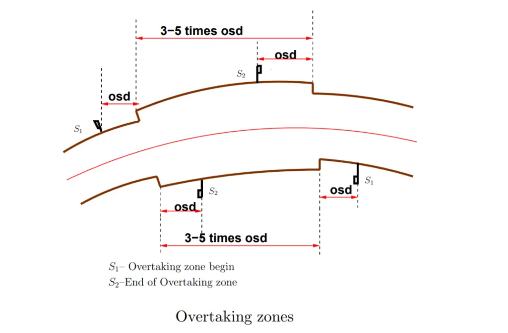
Intermediate sight distance (ISD):
- On a horizontal curve, the requirement of overtaking sight distance can not always be satisfied. In such cases overtaking is prohibited by using regulatory signs. To provide an opportunity for overtaking operation on horizontal curves or in restricted areas, we provide intermediate sight distance, i.e. equals to twice of stopping sight distance.
ISD= 2×SSD
- The measurement of the ISD may be made assuming both the height of eye of driver & height of object to be 1.2m.
- .
| Distance | Reaction Time (sec) | Height (metre) | |
| Driver Eye | Object | ||
| SSD | 2.5 | 1.2 | 0.15 |
| OSD | 2 | 1.2 | 1.2 |
| ISD | 2.5 | 1.2 | 1.2 |
| Space Headway | 0.7 | – | – |
Sight distance at intersections
At intersections where two or more road meets, clear view across the corners should be provided from a sufficient distance to avoid collision of vehicles. The sight distance should be provided in such a way so that driver from both sides can see each other .The area of unobstructed sight formed by the lines of vision is called the sight triangle as shown in
Design of sight distance at intersections may be used on three possible conditions:
• Enabling approaching vehicle to change the speed
• Enabling approaching vehicle to stop
• Enabling stopped vehicle to cross a main road
Curve:
Curves are provided in highways in order that the change of direction at the intersection of straight alignments either in horizontal or vertical plane, shall be gradual.
The necessity of curves arises due to the following reasons:
- Topography of the country
- To provide access to a particular locality
- Restrictions imposed by property
- Preservation of existing amenities
- Avoidance of existing religious, monumental and other costly structures
- Making use of existing right of way
Advantages of Curves
The advantages of providing curves are:
- They provide comfort to the passengers. If there is an abrupt change in the direction nor grade of a highway it will upset the passengers.
- They help to avoid mental strain induced by the monotony of continuous journey along straight path.
- In the case of sharp turns, brakes have to be applied more frequently which reduces the life of tyres. Thus life of the vehicles in increased by providing curves.
- The drivers became alert due to the change in the direction of road.
- They help to keep the speed of the vehicle within limits. On a straight road, a driver is tempted to go at a much faster speed.
Factor Affecting the Design of Curves
The various factors which affect the design of curves are:
- Design speed of the vehicle
- Maximum permissible superelevation
- Allowable friction
- Permissible centrifugal ratio
Type of Curves
Curves have been divided into two classes:
(1) Horizontal Curve: A curve in plan to provide change in direction of the central line of a road.
(ii) Vertical Curve: A curve in the longitudinal section of a roadway to provide for easy change of gradient.
The different types of curves used in highways are:
(i) Simple Circular Curve: A simple cùrve consists of a single are connecting two straights.
(ii) Compound Curve: A compound cùrve consists of a series of two or more simple curves that turn in the same direction and join at common tangent points.
(iii) Reverse Curve: A reverse cúrve consists of two simple curves of opposite direction that join at the common tangent point called the point of reverse curve.
Design of Horizontal Alignment:
Various design element to be considered in the horizontal alignment are:
- Design speed
- Type and length of transition curve
- Width of pavement
- Super elevation
- Radius of circular curve
- Set back distance
Design Speed:
- The design speed is main factor on which most of the geometric design element depends including horizontal elements.
- The design is speed of road depends, upon class of road and terrain.
- Classification of terrain & design speed for different class of road is as follows:
- Design speeds are also being defined for urban roads.
- Two values of speed is ruling and minimum are being specified for each type of Road.
- As far as possible, attempt most to be made to design all the geometric element for ruling speed however it site conditions and economic consideration does not permit so, design must be done for minimum design speed.
Stability Analysis on Horizontal Curve without Superelevation:
It is the curve in plane to provide change in the direction to Central line on the road. When a vehicle travel on a horizontal curve, the centrifugal force act horizontally outward through the center of gravity of the vehicle.
The centrifugal force depends upon the speed of vehicle and the radius of horizontal curve.
It will be counteracted by lateral /transverse friction developed between the tyre & pavement, which helps the vehicle to change direction along the curve.
They are the centrifugal force (P) acting outward, weight of the vehicle (W) acting downward, and the reaction of the ground on the wheels (RA and RB). The centrifugal force P in Newton is given by
P=mv2R
where m is the mass of the vehicle in kg, v is the speed of the vehicle in m/sec, g is the acceleration due to gravity in m/sec2 and R is the radius of the curve in m. The centrifugal ratio or the impact factor PW is given by:
PW=mv2Rmg=v2gR
The force acting on vehicle has the tendency to either overturning the vehicle outward about wheels & to skid the vehicle laterally outward.
1. Overturning the vehicle
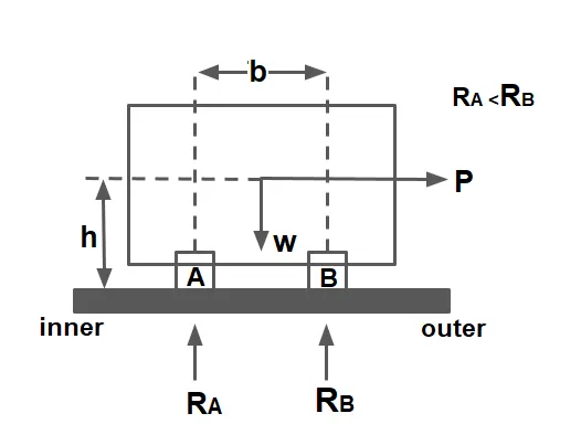
MO= P×h= Overturning Moment
MR= W×(b/2)= Resistive Moment
Case.1 To avoid overturning:
MO < MR
P×h< W×(b/2)
I= PW<b2h
Case.2 On the verge of overturning:
MO = MR
P×h= W×(b/2)
I= PW=b2h
Case.3 Unsafe case:
MO > MR
P×h> W×(b/2)
I= PW>b2h
2. Lateral skiding of the vehicle
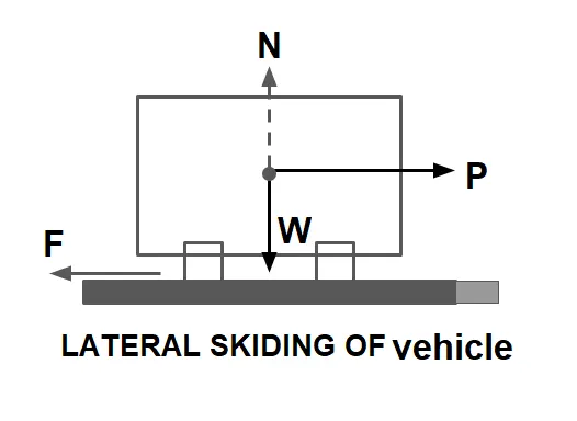
Skiding Force= P= mv²R
Resistive Force= F= f·W= f·m·g
Case.1 To avoid skiding:
P< f×W
I= PW<f
Case.2 On the verge of skiding:
P= f×W
I= PW=f
Case.3 Unsafe case:
P> f×W
I= PW>f
Note:
- If pavement is kept horizontal across the alignment, The pressure on the outer will be higher due to centrifugal force acting outward direction.
- When the limiting equilibrium condition for overturning occurs, the pressure at inner wheel becomes zero.
- Since pressure on outer wheel is comparatively more, it damages the pavement by developing ruts over it. RUTTING FAILURE
- Hence to avoid both overturning & sliding :
I=PW≤⎧⎩⎨⎪⎪b2handf
- The relative dangerous of lateral skidding and overturning depends upon weather ‘f’ is lower or higher than b2h.
- If
f< b2h⇒ Transverse of skidding before overturning.
f> b2h⇒ Overturning before transverse skidding.
Superelevation:
The transverse inclination throughout the length of horizontal curve by raising outer edge counteract w.r.t. inner edge, in order to counteract the effect of centrifugal force is known as superelevation
The superelevation ‘e’ is expressed as the ratio of height of outer edge w.r.t. the horizontal width, i.e
Superelevation (e)= NLML
e= tanθ
θ is very small and the value of tanθ ⊁ 0.007 (7%)
e= tanθ ≅ sinθ = EB
Analysis for Expression of Super-elevation
Consider a vehicle moving at a speed of v m/s on a circular curve having radius ‘R’.
The following forces acting on the vehicle:
i) Centrifugal force (P) acting horizontally through the center of gravity (CG) of vehicle
P= mv²R=W⋅v2gR ——-(1)
ii) The weight (W) of the vehicle action vertically downwards through the C.G. of the vehicle
iii) The frictional force (FA & FB) developed between the wheels and pavement, transversely along the pavement surface.
FA =RA ×f and FB =RB ×f ——-(2)
where
RA and RB = frictional resistance between wheel and pavement
f = coefficient of lateral friction
Considering equilibrium, the component of centrifugal force parallel to the pavement (Pcosθ) is opposed by component of weight parallel to the pavement and frictional force FA and FB,
P cosθ= W sinθ + (FA + FB )
P cosθ= W sinθ + f(RA + RB )
P cosθ= W sinθ + f(P sinθ+ W cosθ )
P(cosθ- sinθ)= W(sinθ +fcosθ)
PW=sinθ+fcosθcosθ−fsinθ
dividing by cosθ on right side term
PW=tanθ+f1−ftanθ.
from equation 1 PW=v2gR.
v2gR=tanθ+f1−ftanθ.
v2gR=e+f1−ef.
Here, Coefficient of lateral friction ( f ) = 0.15
Maximum value of super-elevation (tanθ) = 0.07 (7 %)
1-e·f= 0.99≅ 1 (As per IRC)
hence
e+f=v2gR , v in m/sec
Here, e = rate of super-elevation = tanθ
If the speed of vehicle is represented as V kmph then
Formula for Superelevation
e+f=V2127R , V in km/h
Note: For Racing Track
e+f1−ef=v2Rg, v in m/sec
Equilibrium Superelevation:
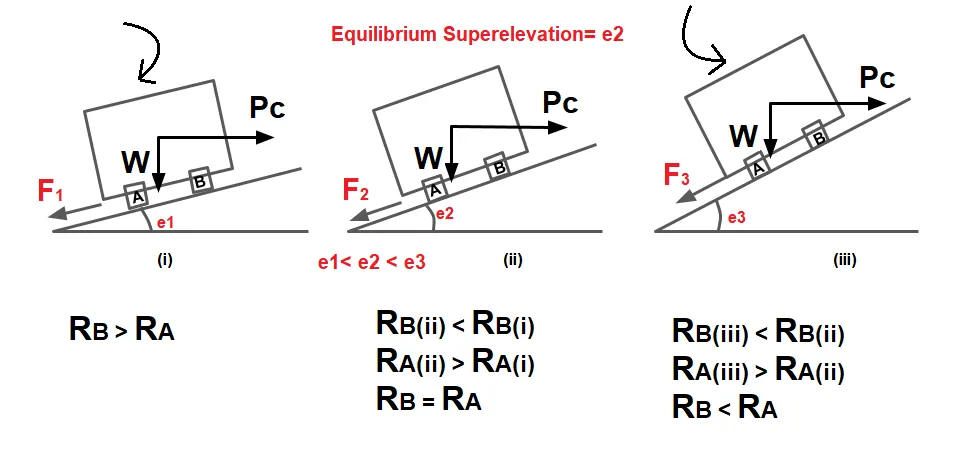
Equilibrium superelevation is that superelevation at which pressure at the inner and outer tyre will be equal. if the coefficient of friction is neglected i.e. f =0 then,
e=V2127R , V in km/h
This means that if a road surface is super elevated by tan-1V2127R then the friction force will not be called upon to act and thus the pressure on both the wheel will be equal.
eequilibrium =V2127R
If the superelevation provided is less than eequilibrium lateral fiction will come into play and will go on increase as the superelevation gets reduced.
Note⇒ Due to equilibrium superelevation:
- No overturning, No Toppling, No Skidding, No Sliding.
- Pressure at the inner and outer tyre will be equal.
Superelevation As Per IRC
1.Maximum Superelevation
| Type of Road | Maximum Superelevation (emax) |
| Urban Road | 4% or 0.04 |
| Plain & Rolling Terrain | 7% or 0.07 |
| Mountainous & Steep Terrain | 10% or 0.10 |
2.The minimum superelevation
It is provided on a road must not be less than the camber of the road for the adequate drainage of water from the surface.
Design of Superelevation⇒
Design of superelevation is a complex problem for mixed traffic conditions because different vehicles are moving with different speed hence the required superelevation are also different.
In this case IRC suggest to design the superelevation for 75% of the design speed considering coefficient of friction is 0.
Step.1: The super elevation is calculated for 75% of design speed, neglecting the lateral friction.
e+f=V2127R, V in km/h
for design, f=0, V=0.75V.
e =(0.75V)2127R.
e =V2225R.
Step.2: If the calculated value of ‘e’ is less than 7%, so obtained ‘e’ is provided. If the value of ‘e’ is more than 7%, then provided e= emax (7%) check for lateral friction also
Step.3: Check for friction developed for maximum value of e=7% at full value of design speed.
e+f=V2127R.
f=V2127R-e.
f=V2127R-0.07.
If the value of ‘f’ calculated is less than 0.15, the superelevation of 7% is safe for the design but if it comes out to be more than 0.15, then if speed of vehicle has to the restricted to safe value. which is less than design speed.
Step.4: The allowed level speed at the car peach computed as follows
e+f= V2127R.
0.07+0.15= Va2127R.
VA =5.25R−−√
- If the allowable speed is higher than design speed then the design speed is adequate but it is less than design speed, the speed is limited to the allowable speed.
- Speed can be reduced by warning signs of yi speed limit regulations sign.
- On important highways as for as possible speed is not reduced hence the curve should be realigned with a larger radius of curvature.
Method of Obtaining Superelevation:
Introducing superelevation on a horizontal curve in the field is an important feature in construction. The full super-elevation is attained by the end of transition curve or at the beginning of the circular curve.
The attainment of superelevation may be split up into two parts:
- Elimination of crown of the cambered section
- Rotation of pavement to attain full superelevation
i) Elimination of crown of the cambered section
Method 1
In this method, the outer half of the cross-slope is rotated about the crown at a desired rate such that the surface falls on the same plane as the inner half and the elevation of the center line is not altered.
The outer half of the cross-slope is brought to level or horizontal at the start of the transition curve or at tangent point (T.P.). Subsequently the outer half is further rotated so as to obtain uniform cross-slope equal to the camber.
This method has a drawback that the surface drainage will not be proper at the outer half.
Method 2
In this method, the crown is progressively shifted outwards, thus increasing the width of the inner half of cross-section progressively. This method is not usually adopted as a portion of the outer half of the pavement has increasing value of negative super-elevation.
ii) Rotation of pavement to attain full super-elevation
When the crown of the camber is eliminated, It does not signify that superelevation desired at that section is attained.If desired superelevation is more than camber/ cross sections for the payment section will have to be rotated for the till the desired superelevation is attained.
Desire superelevation can be attained by two method:
Method 1
By rotating the pavement cross section about the centre line, depressing the inner edge & raising the outer edge each by half the total amount of superelevation required with respect to centre.
Method 2
By rotating the pavement cross section about the inner edge of the pavement raising both centre as well as the outer edge of the pavement such as the outer edge is raised by the full amount of superelevation desired.
| Rotation about center line | Rotation about inner edge |
| It may with interfere drainage system. | No interference with drainage system. |
| Centre line remain unchanged. | Centre line is elevated. |
| Earth work is balanced in cutting & filling. | Filling is required. |
In cases where a transition curve cannot be provided for some reason, 2/3 of superelevation may be attained at the straight portion before the start of the circular curve and the balance 1/3 is provided at the beginning of the circular curve.
The superelevation is introduced by raising the outer edge of pavement at a rate not exceeding (1 in 150) in plain & rolling terrain and (1in 60) mountainous & steep terrain.
Radius of Horizontal Curve
Horizontal curve of highways are designed for the specified design speed (Ruling & Min).
However if this is not possible due to site restriction, the horizontal curve may be redesigned.
On the basic of speed Radius of Horizontal Curve is classified into following:
1.Ruling Minimum Radius(RMR)
e+f=V2127R.
RMP=V2127(emax+f).
V= Ruling design speed (kmph)
2.Absolute Minimum Radius(AMR)
e+f=V′2127R.
AMR=V′2127(emax+f).
V’= Ruling design speed (kmph)
3.Radius beyond which no superelevation is required (RBNSN):
It is the radius, corresponding to which camber serve the purpose of superelevation.
e+f=V2127R.
e=camber, f=0, V=V0.75
camber=0.75V2127R.
RBNSN=V2225×camber.
ExtraWidening:
Extra width provide to Road at horizontal curve is called extrawidening.
It is provided for following purposes:
-
To avoid off tracking due to rigidity of wheel base.
-
To encounter psychological tendency of driver.
-
To increase visibility at curve.
- To account lateral skidding.
Off tracking:
Path travelled by front axle and path travelled by rear axle it is not same on horizontal curve this phenomena is called off tracking.
Extrawidening is split up into two parts.
-
Mechanical widening
-
Psychological widening
WE= WM+WP
WE= Extra widening
WM =Mechanical widening
WP= Psychological widening
(i) Mechanical widening:
Mechanical widening is provided to account off tracking.
R22=R21+l2.
R22=(R2−WM)2+l2.
R22=R22−2R2WM+W2M+l2.
2R2WM−W2M=l2.
WM=l22R2−WM≅l22R. where, R= mean radius of curve.
WM=l22R.
Now for ‘n’ lane Road
WM=nl22R.
(ii) Psychological widening:
There is a psychological tendency of driver to drive the vehicle close to the edge of pavement and maintain more side gap between the vehicle moving parallely.
WP=V9.5R√.
Where WP in m, R in m, V in KMPH.
WE= WM+WP
WE= nl22R+V9.5R√.(extra widening formula)
Note
IRC recommended value of extra widening for single and tow lane pavement are given below.
-
For single lane road Psychological widening =0.
-
If R> 300 m, then extra widèning is not provide.
-
If R< 50 m, then extra widèning is provided at inner edge.
-
If 50<R<300 m, then extra widèning is provided at both the edge.
Transition Curves:
When a vehicle traveling on a straight road enters into a horizontal curve instantaneously, it will ca discomfort to the driver. To avoid this, it is required to provide a transition curve. This may be provided either between a tangent and a circular curve or between two branches of a compound or reverse curve.
Transition curve has a radius equal to infinite when it meets to straight Road within gradually change to designate radius towards the circular curve.
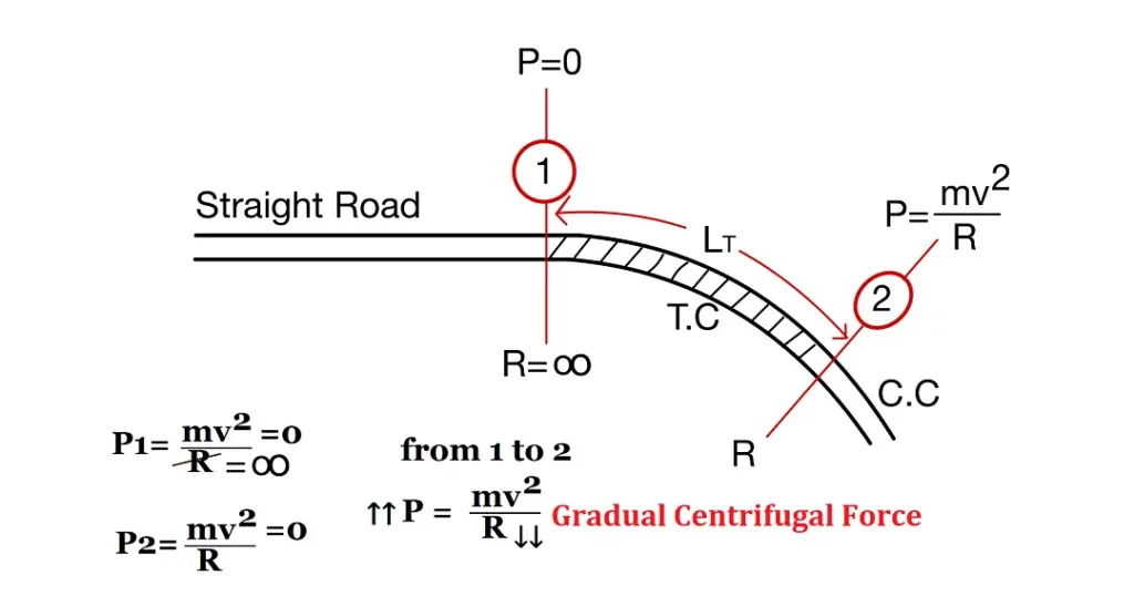
The objectives of providing a transition curves are:
- To gradually introduce the centrifugal force between straight and circular curves.
- To avoid the certain jerk.
- To gradual introduction of superelevation and extra widening.
- To enable the driver turn the sheering gradually for comfort and security.
- To improve aesthetic appearance.
A transition curve should salisty the following conditions
- It should meet the straight path tangentially.
- It should meet the circular curve tangentially.
- It should have the same radius as that of the circular curve at its junction with the circular curve.
- The rate of increase of curvature and superelevation should be the same.
The length of transition curve required on a horizontal highway curve depends upon the following factors:
- Radius of circular curve, R
- Design speed, V
- Allowable rate of change of centrifugal acceleration, C
- Maximum amount of super elevation, E which depends on the maximum rate of superelevation, e and the total width of the pavement, B at the horizontal curve.
- Rotation of pavement cross-section either about the inner edge or the centre line
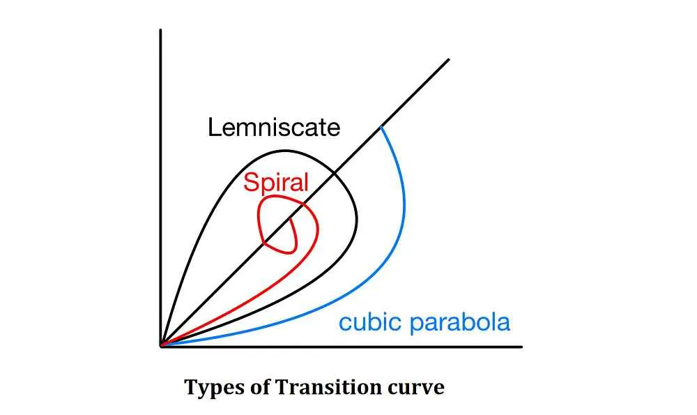
Different Types of Transition Curves
The types of transition curves commonly adopted in horizontal alignment of highways are:
1.Spiral
2.Bernoulli’s Lemniscate
3.Cubic Parabola
NOTE:
- In all these curve the radius decreases at length increases.
- But the rate of change of radius or rate of change of centrifugal force is not constant in case of Lemniscate and cubic parabola.
- Hence a spiral curve is used as transition curve as it fulfills the requirement of ideal transition curve.
- According to IRC an ideal transition curve is spiral because rate of change of radial acceleration (C) remains constant.
Length of Transition Curve
The length of transition curve is designed to fulfill three conditions:
- Rate of change of centrifugal acceleration to be developed gradually
- Rate of introduction of the designed superelevation to be at a reasonable rate, and
- Minimum length by IRC empirical formula
The length of transition curve following three conditions:
Length of Transition Curve by the Rate of Change of Radial Acceleration
Length of Transition Curve is designed such that the rate of change of centrifugal force is low.
Rate of change of centrifugal acceleration:
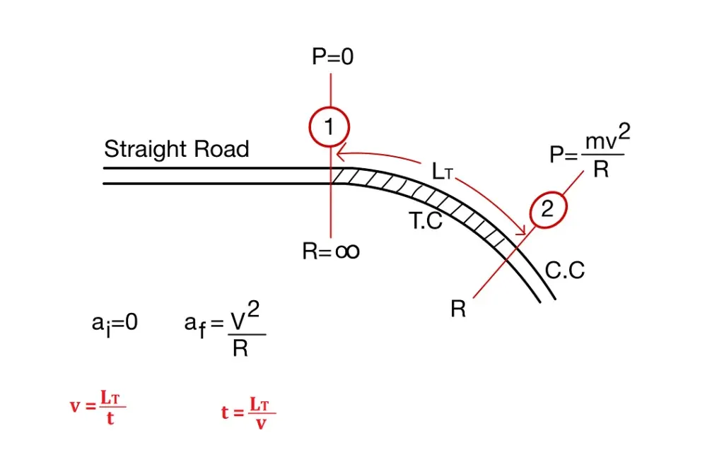
|
v=Velocity of the vehicle in m/s |
R= Radius of the curve in m |
|
C= rate of change of radial acceleration in m/sec3 |
LT= Length of Transition Curve in m |
|
t= time taken by vehicle in second to travel the transition length at speed v. |
|
| LT=v3C⋅R |
(Here,v in m/s) |
|
or |
|
|
LT=0.0215V3C⋅R |
(Here,V in km/s) |
The rate of change of centrifugal acceleration is given by an empirical formula recommended by IRC
|
C=8075+Vm3/s |
(Here,V in km/s) |
Subject to a maximum of 0.8 and minimum of 0.5.
Length of Transition Curve by Rate of Change of Superelevation
Rate of introduction if superelevation = 1V in NH
1= elevation provided
N= Length of Transition curve
Rate As per IRC
| 1:150 For Plain and Rolling terrain | 1:100 For Urban /Built Up Area | 1:60 For Hilly Area |
The length of transition curve = N·x
where x is elevation of outer edge.
(i) When pavement is rotated about inner edge
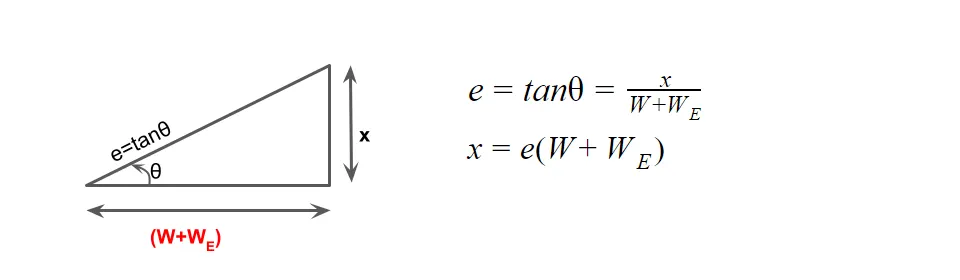
LT=eN(W+WE)
W=Width of pavement
WE= Extra widening
(ii) When pavement is rotated about centre
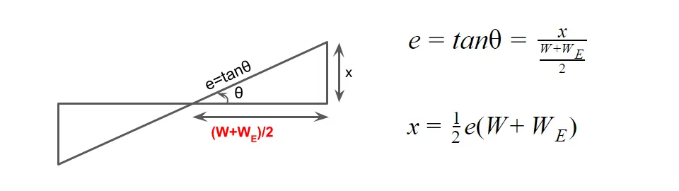
LT=12eN(W+WE)
Empirical Formula for the Length of Transition Curve Recommended by IRC
| For plain and rolling terrain, | LT=2.7V2R |
| For mountainous and steep terrain, |
LT=V2R |
|
V→kmph |
R→m |
LT→M |
Setting Out of Transition Curve
When a Transition curve is introduced between a straight and circular curve, then circular curve has to be shifted so that the transition curve meets the circular curve tangentially. The shifted (S) of a circular curve is given by
|
S=L2T24R |
LT= Length of transition curve |
Set Back Distance:
It is clearance distance, required from the centre line of pavement/road to the obstruction in ode to maintain the adequate sight distance to the curve.
The set back distance or clearance required from the centre line of horizontal curve depends upon.
- Required sight distance (SD)
- Radius of horizontal Curve (R)
- Length of curve(LC)
Calculation Of Setback Distance
There are two cases in the calculation of setback distance:
Case 1: When the length of horizontal curve greater than the sight distance (LC>SD).
(a) For Single Lane:
In single lane road the sight distance is measured along the centreline of the road.
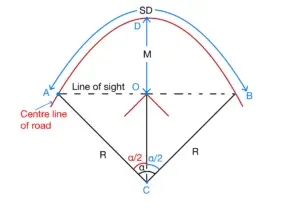
| Set back distance (m)= OD | CD=AC=R |
| m=CD–CO |
In Δ ACO cosα2=COAC |
| CO=R⋅cosα2 | |
| m=R−R⋅cosα2 | |
| α2=SD2R(Radians) | |
| OR | |
| α2=180ΠSD2R(Degrees) | |
(b) For Multi lane:
In multi lane road the sight distance is measured along the centreline of the inner lane and the set back distance is measured from the centre of road.
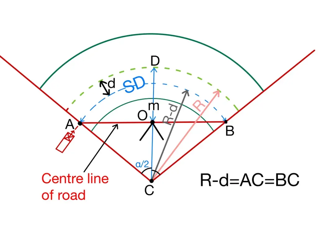
Let “d” be the distance between the centre line of road & centre line of the inside lane.
| d=W+WE4 | |||
| α2=SD2(R−d)(Radians) | |||
| OR α2=180ΠSD2(R−d)(Degrees) | |||
| Set back distance (m)= OD | DC=R | ||
| m=DC–OC |
In Δ ACO cosα2=OCAC |
||
| OC= ACcosα2= (R-D)cosα2 | |||
| m=R−(R−d)cosα2 | |||
Case 2: When the length of horizontal curve less than the sight distance (LC<SD).
(a) For Single Lane:
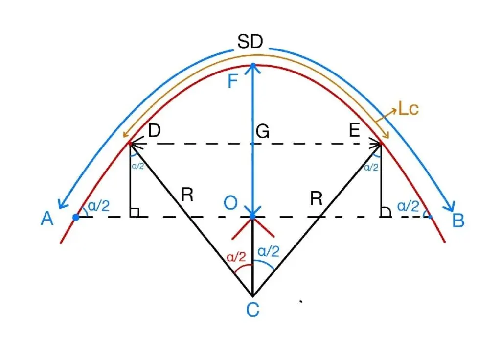
| Set back distance (m)= FO= FG+OG | |
|
FG=FC-GC FC=R GC=Rcosα2 FG=R-Rcosα2 |
OG=DI=ADsinα2
AD=SD−LC2 OG=(SD−LC2)sinα2 |
| m=R−R⋅cosα2+(SD−LC2)sinα2 | |
| Here α2=LC2R(Radians) | |
| or α2=180ΠLC2R(Degrees) | |
(b) For Multi lane:
m=R−(R−d)⋅cosα2+(SD−LC2)sinα2
Here
α2=LC2(R−d)(Radians)
OR
Design of Vertical Alignment
Generally Highway is aligned to follow the natural topography keeping in view the drainage and other design consideration.
The vertical alignment of a highway affects:
-
Acceleration & Deceleration
-
Operational cost of vehicle
-
Sight distance
-
Vehicle speed
The vertical alignment consist of two element:
1. Gradient |
2. Vertical curve |
Gradient:
It is designed a change in elevation/height of road along the length or maybe defined as rise or fall along the length of road with respect to horizontal.
Slope due to gradual rise or gradual fall in the direction of vehicle movement is called gradient.
If it is gradual rise then the slope is called ascending /rising /positive gradient.
If it is a gradual fall then the slope is called descending/ falling/negative gradient.
It can be represented as follows:
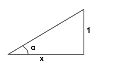
- 1 in x (1 vertical to x horizontal)
- 1x×100
- tanα
Note: The angle which measures change in direction at the intersection of two grades is called as deviation angle.
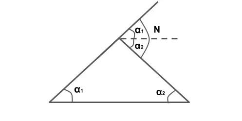
N= α1+α2
or N=α1-(-α2)
Type of Gradients:
Gradients are divided into following types.
- Rulling Gradient
- Limiting Gradient
- Exceptional Gradient
- Minimum Gradient
Ruling Gradient:
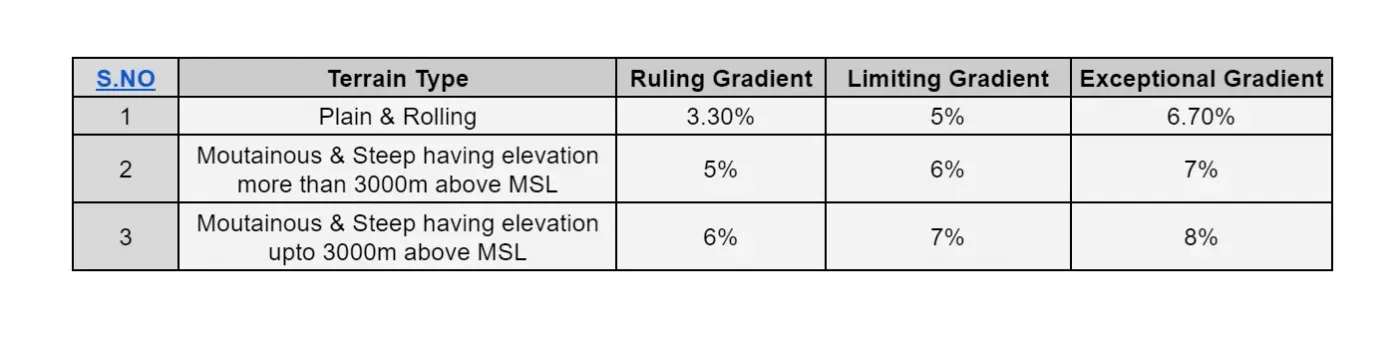
It is the maximum gradient within which designer wants to design the vertical profile of the road, hence it is also known as design gradients. It depends upon topography, length of the grade, design speed, pulling power of vehicle and presence of horizontal curves.
Limiting Gradient:
It is steeper than ruling gradient and it is provided only when there is an enormous increase of cost of construction with ruling gradient. On rolling and hilly terrain, limiting gradient may be frequently adopted but the length of limiting gradient stretch should be restricted.
Exceptional Gradient:
It is steeper than ruling gradient and limiting gradient and provided only, if the situation is unavoidable. Length of exceptional gradient stitch should not be more than 100 m.
Minimum Gradient:
It is provided along the length of road for drainage point of view. Minimum gradient for cement concrete drain is 1 in 500.
As per IRC minimum gradient is as follows:
| Concrete drainage | 1/500 |
| Kutcha open drainage / Soil drainage | 1/ 200 |
Note: Depending upon the type of soil it can be taken up to 1/100.
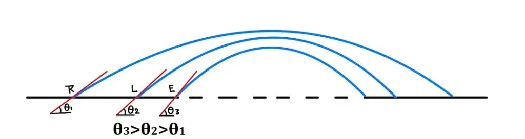
Steeper ⇒ EG>LG>RG>MG
Note: Grade Compensation at Horizontal Curves
When there is a horizontal curve in addition to gradient then there will be increased resistance to traction due to both curve and gradient. Therefore it is necessary to reduction in gradient at horizontal curve.
This reduction in gradient at the horizontal curve is termed as “Gradient Compensation“, which is given by
GC%=30+RR
R= Radius of horizontal curve
Grade compensation as taken is minimum of 30+RR% or 75R%, where ‘R’ is the radius of curve in metres.
Compensated gradient =Gradient-Grade compensation