INTERN PROJECT - 1 - [Two- Stroke ENGINE ASSEMBLY]
AIM:
- To check for geometrical errors and perform Topology cleanup accordingly.
- To perform surface wrap on the given automotive assembly.
- Make a volumetric mesh in the given geometry, then make a surface mesh so we can proceed with the volumetric mesh, and finally select the required volumes and create a volumetric mesh in those volumes.
PROBLEM STATEMENT:
- Create a Watertight Model for The CFD Simulation using ANSA
- The model should be simplified According to the flow Analysis Application
- All the geometry features should be captured properly
- Surface mesh using Tria elements, Skewness < 0.6
- No Intersection Errors
- 5 layers of Prism Mesh
- Volumetric mesh using tetrahedral elements
Software Used:
- ANSA v22.1.0.
INTRODUCTION:
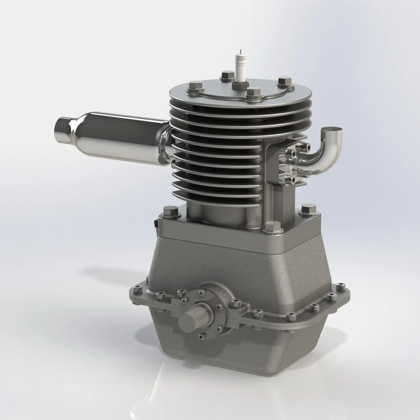
RECEIVED MODEL: ENGINE ASSEMBLY OF TWO-STROKE ENGINE.
LITERATURE REVIEW:
- Gone through various research papers to study the various element size for meshing different parts.
- Also, to do a study of prism mesh and volumetric mesh. I have attached the research papers with the report file.
Two-Stroke Engines: Defining Their Purpose:
In a four-stroke engine, each of the four essential steps of the power-producing cycle is given its piston stroke:
1) Compression
2) Power
3) Exhaust
4) Intake
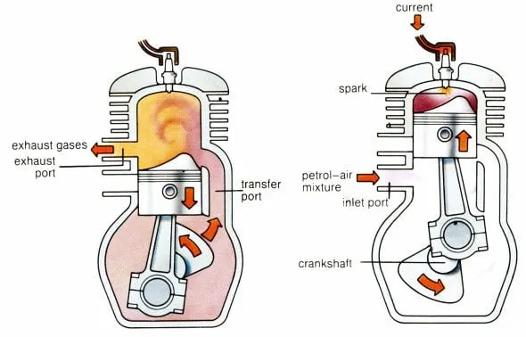
- A two-stroke engine performs all the same steps but in just two piston strokes. The simplest two-stroke engines do this by using the crankcase and the underside of the moving piston as a fresh charge pump. Such engines carry the official name "crankcase-scavenged two-strokes."
- As the two-stroke piston rises on compression, its underside pulls a partial vacuum in the crankcase. An intake port of some kind (cylinder wall port, reed valve or rotary disc valve) opens, allowing air to rush into the crankcase through a carburettor.
- As the piston nears Top Dead Center, a spark fires the compressed mixture. As in a four-stroke, the mixture burns and its chemical energy becomes heat energy, raising the pressure of the burned mixture to hundreds of psi. This pressure drives the piston down the bore, rotating the crankshaft. As the piston continues down the bore, it begins to expose an exhaust port in the cylinder wall. As spent combustion gas rushes out through this port, the descending piston is simultaneously compressing the fuel-air mixture trapped beneath it in the crankcase.
- As the piston descends more, it begins to expose two or more fresh-charge ports, which are connected to the crankcase by short ducts. As the pressure in the cylinder is now low and pressure in the crankcase higher, the fresh charge from the crankcase rushes into the cylinder through the fresh-charge (or “transfer”) ports. These ports are shaped and aimed to minimize the direct loss of fresh charge to the exhaust port. Even in the best designs, there is some loss, but simplicity has its price! This process of filling the cylinder while also pushing leftover exhaust gas out of the exhaust port is called “scavenging.”
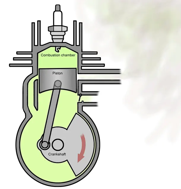
- While the piston is near Bottom Dead Center, the mixture continues to move from the crankcase, up through the transfer ports, and into the cylinder. As the piston rises, it first covers the transfer ports, leaving only the exhaust port still open. If there were no way to stop it, much of the fresh charge would now be pumped out of the exhaust.
- But there is a simple way to stop it—using exhaust pressure waves in the exhaust. If we shape and dimension the exhaust pipe right, a reflection of the original pressure pulse, generated as the exhaust port opened, will bounce back to the port just as a new charge is being pumped out of it. This pressure wave stuffs the fresh charge back into the cylinder just as the rising piston covers the exhaust port.
- Because the fuel-air mixture is constantly being pumped by the crankcase, it is not practical to lubricate the piston and crank with pumped circulating oil—it would be swept away by the mixture rushing in and out. Therefore, we must either mix a little oil with the fuel (2 to 4 per cent) or inject it very sparingly into the bearings with a tiny metering pump. The fact that there is so little oil dictates that such simple two-stroke engines must employ rolling bearings, whose need for oil is minimal.
- More complicated two-stroke exist. Instead of using the crankcase and underside of the piston as a fresh-charge pump, we can use a separate rotary blower, directly connected to the transfer ports in the cylinders. We don't have to place the exhaust port in the cylinder wall—it can take the form of four overhead poppet exhaust valves, as it does in two-stroke marine, rail, and truck diesel. Because such engines do not use their crankcases as fresh charge pumps, they can employ long-lasting plain bearings, lubricated conventionally by pumped recirculating oil.
- Two-stroke diesel is scavenged with pure air, not a fuel-air mixture. Their fuel is injected only after all ports have closed, preventing loss. Certain crankcase scavenged two-strokes do the same, and are called “DI,” or Direct Injection two-strokes. They can be made as fuel-efficient and low in exhaust emissions as four-strokes.
- The world’s most efficient piston engines are in fact the giant, slow-turning marine diesel that carries the world’s international shipping trade—they are twice as efficient as the usual four-stroke spark-ignition engines found in cars and motorcycles.
PROCEDURE:
Watertight Model (SURFACE WRAP):
- To create a Watertight Model for The CFD Simulation using ANSA.
- Open the geometry in the ANSA software. Clean up the surface of the geometry by deleting unwanted parts and faces present on the geometry. As surface wrapping is generally carried out to study the flow over a surface So the main importance should be outside surface rather inside parts and surface.
- Close all the holes present in the geometry otherwise while wrapping it might create disturbances. The below diagram shows the final geometry before assembly.
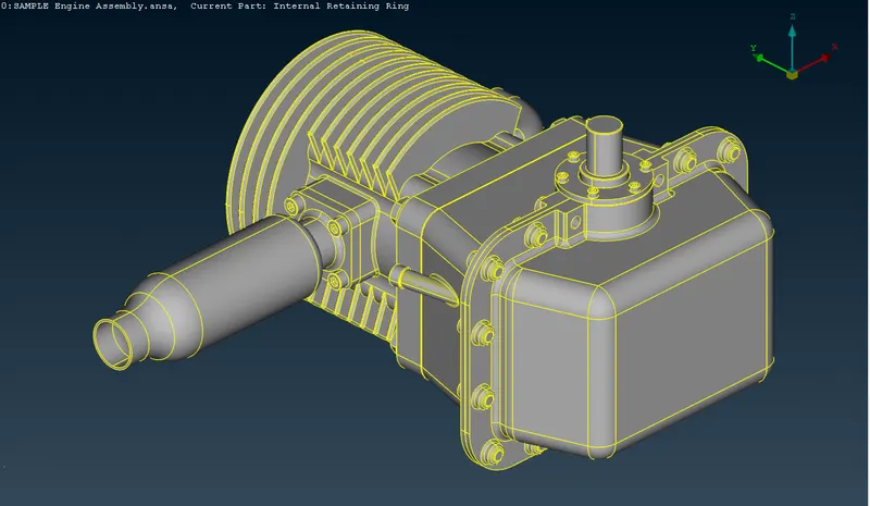
- Now move to the mesh session and select the Wrap option from the element dropdown. In wrapping select constant length as in this it is a constant length surface wrapping.
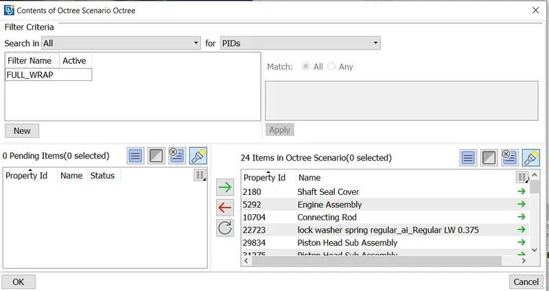
- Provide target length and smooth factor as 2 and 0.5 respectively. Smaller target length help to create more accurate wrapping though it might take time. Then provide content by selecting all the PIDs and clicking ok.
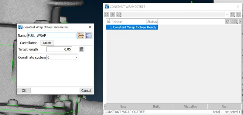
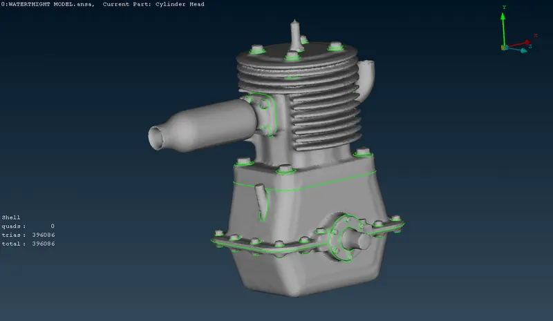
- Surface wrapping is generally carried out to study the flow over a surface so, the main focus should be outside surface rather inside parts and surface. The below figure shows the surface meshed model of the given automotive assembly.
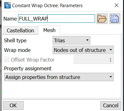
- Select all the PIDs to octree to run the surface wrap.
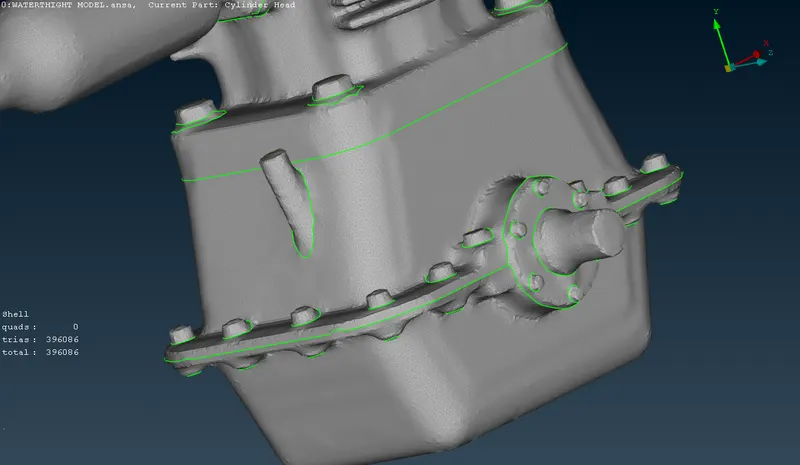
- After surface meshing to check whether the wrap obtained is correct, it is advised to check the inside of the wrapped surface. If it creates a pure hollow inside (as shown in the below figure) thus proper surface wrapping is obtained.
- Hence the Watertight Model for The CFD Simulation using ANSA is done according to the problem statement.
SURFACE MESH:
Meshing: A mesh is a representation of a larger geometric domain by smaller discrete cells. By meshing, you break the domain into pieces and each piece represents an element.
- meshing process: define element size -> choose the size of element -> select the type of mesh to do -> quality criteria check -> remesh for quality improvement if needed.
PROCEDURE:
- OPEN THE MODEL: Open the model in ANSA as you see in the below image (Topo Cleaned up Geometry).
- Errors are cleared using topo clean-up tools by filling up the surfaces using different methods, namely using coons, fitted, and the existing surfaces.
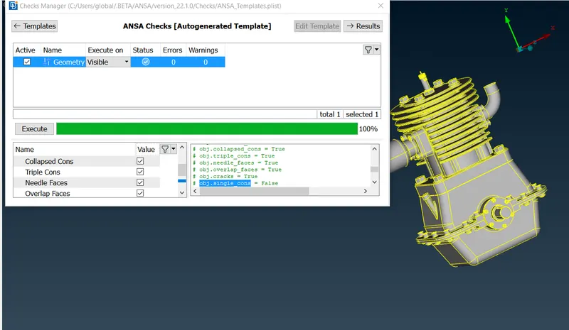
- Now the geometry file is cleaned up and checked once again with the checks manager.
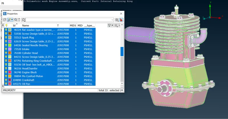
- Using Properties the various shell naming selection has been given.
MESHING:
- Now going for the mesh option here we are considering the following terms,
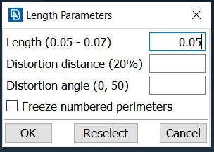
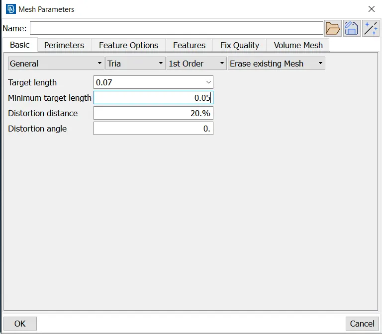
- the length parameters have to be given as 0.05 as you see in the below image.
- Because the length of the parameters, in this case, is 0.05, the best-suited wrap was found while performing the surface wrap with various parameters ranging from 1 to 0.05. So here, the length was considered 0.05 for both the perimeters and macros.
- Target length = 0.07 mm
- Element type = Tria
- Now in the perimeter, the length parameters have to be given as 0.5 as you see in the above image.
- The meshing has been done part by part as per the PIDs in the properties.
- Then we have to give mesh length by selecting the length under parameters and then select the PIDs by drag and drop then click the middle mouse. and give the mesh length as required at present we give mesh length 0.07.
- Same as followed in the Mesh target size and providing the same minimum element quality and here we are using the tria method for the element.
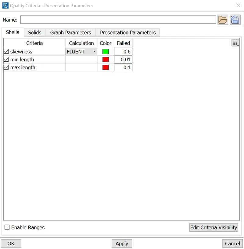
- Giving quality minimum size as 0.01 mm and maximum size of element as 0.1 mm. The skewness for the surface mesh was about 0.6 according to the problem statement the case setup has been done as you can see from the below image.
- The quality criteria are accomplished according to the problem statement.
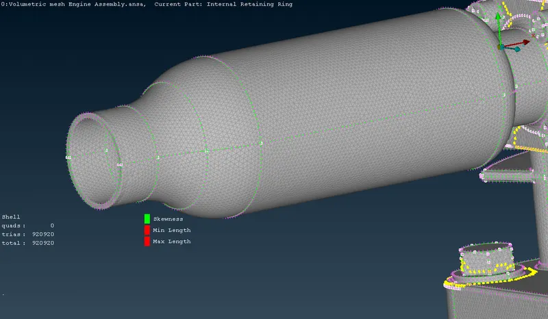
- At present we use spot mesh. To do spot mesh we have to select spot mesh under mesh generation and then select the whole model. before clicking the middle mouse we have to check the option list at the bottom. As of now, we need the tria elements we have selected and reconstruct to be enabled.
- Meshed Exhaust PIDs are shown in the below image.
- Meshed Inlet, Cylinder top and spark plug PID,
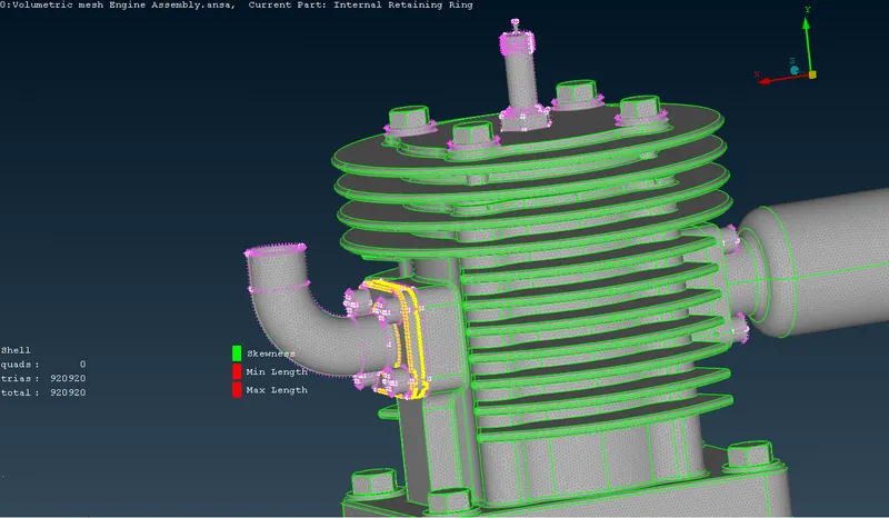
- Meshed Engine block, oil seal, Oil pan PIDs,
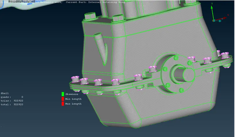
- The total no of tria elements under 0.07 mm is 920920 for the whole Engine assembly.
- All the off elements are cleared using element tools.
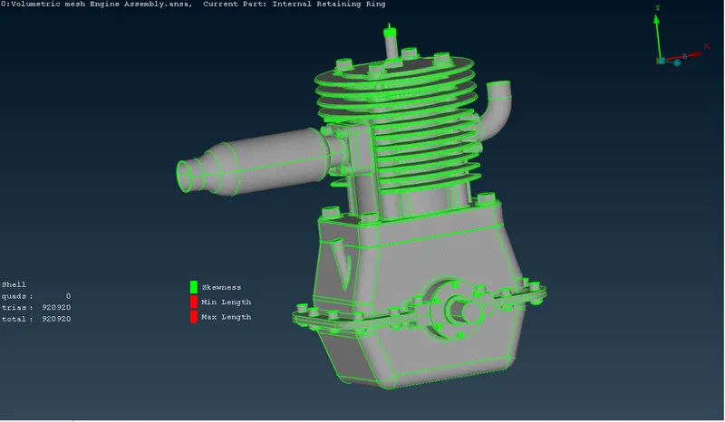
- Surface meshed Engine assembly with different PIDs.
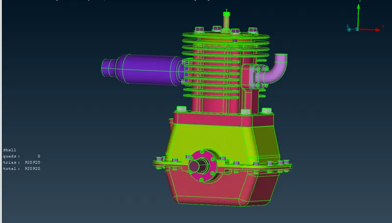
- The focus of the target length (0.07) is to achieve With fine mesh size, the accuracy increases but the time for calculation also increases.
- Hence the surface mesh has been done according to the problem statement.
PRISM MESH:
Prismatic Elements in the Boundary Layer:
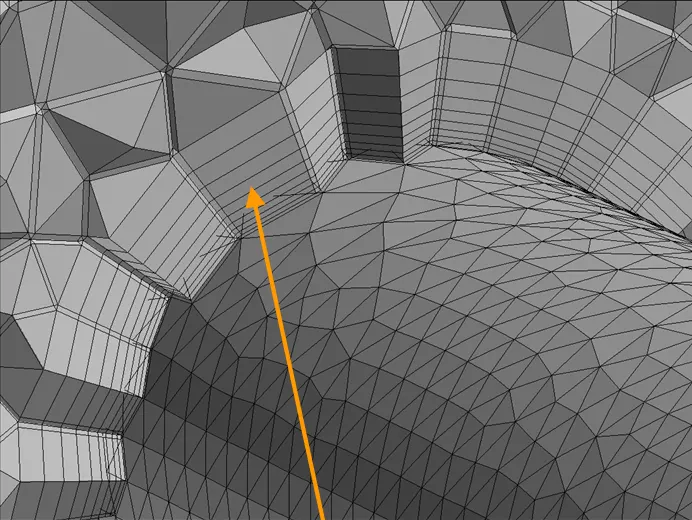
- Triangles on the boundary surface are used as a starting point to create layers of prismatic elements in the near-wall regions. The structured nature of the prisms (wedges) in the normal to surface direction exploits the advantages of traditional structured grid approaches. In particular, prismatic grids offer good orthogonality and clustering capabilities. The algebraic marching procedure is extremely fast and efficient. The CENTAUR prismatic grid generator also provides the added feature of marching along arbitrary boundary surfaces.
- The orange Arrow marks represent the prism layers.
ERRORS FACED:
- Here started doing the prism mesh, but the intersection occurs at various locations.
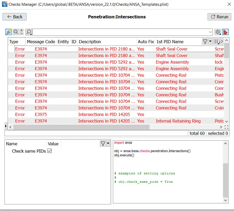
- For the whole geometry, this is the crucial part I faced while doing the meshing. It took more than a week to clear that intersection in the geometry.
- Hence all the intersection has been cleared.
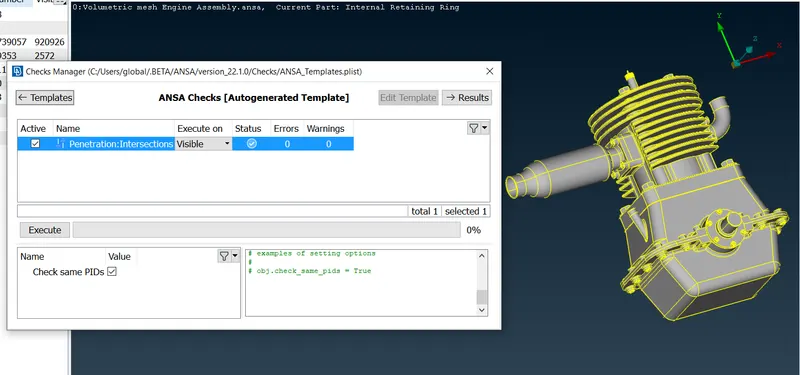
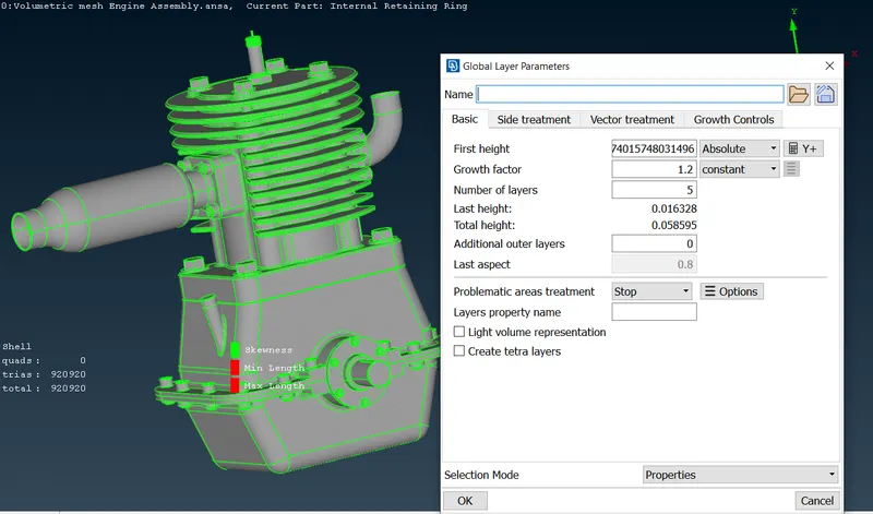
- In classic mesh, using the layers tool as we can see in the below image.
- The first layer of height is about 0.007 and the number of layers is 5 that have been considered for the prism mesh. Other values are retained by default.
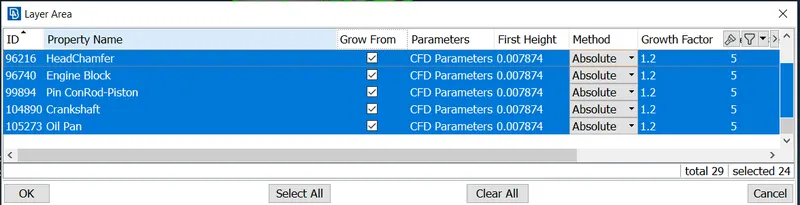
- Selecting all the PIDs for the Prism layer, The growth factor is set to 1.2, and the total no of layers is 5.
- The Prism layers are done for all the volumetric regions. a sectional view is shown in the below image.
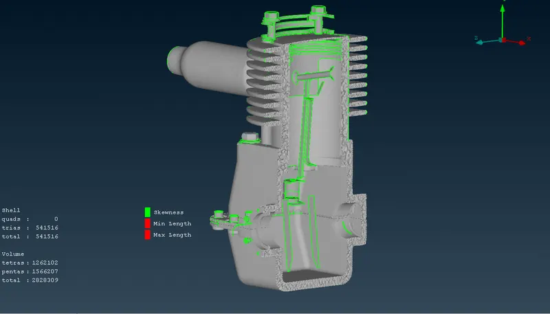
- As you can see now the 5 layers of prism mesh in the PIDs region.
- The total no of Pentas is 1566207.
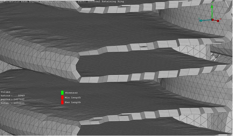
- Prism mesh in OIL PAN PID. Hence according to the problem statement, the intersection has been cleared and the 5 layers of prism mesh are done.
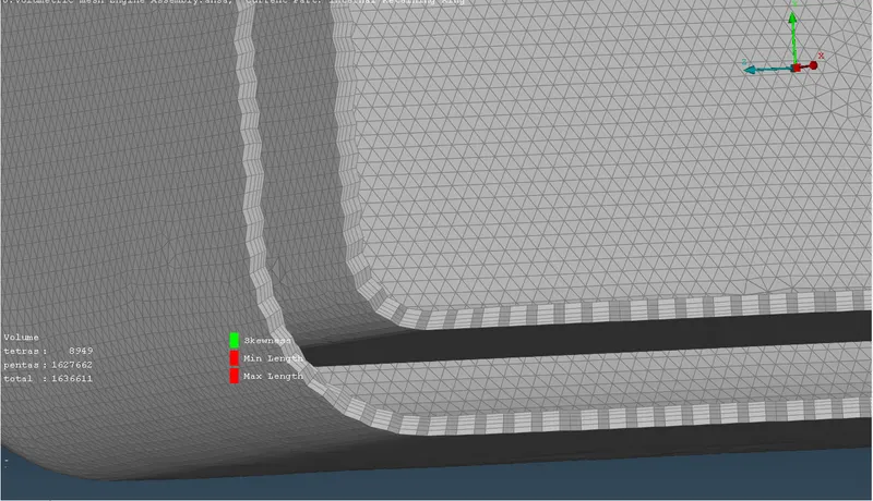
VOLUMETRIC MESH:
- Make a volumetric mesh in the Engine assembly given geometry by first cleaning the geometry and removing any flaws, then making a surface mesh so we can proceed with the volumetric mesh, and finally selecting the required volumes and creating a volumetric mesh in those volumes.
- Volumetric meshing can only be done after 2D meshing, now to check which volumes are capable of getting a mesh we can use DEFINE from volume and the whole-body option then Ansa will show all the volumes present in the body.
- We need to check which volume is actually the volume in which fluid is going to be present and which other is only a thickness of our solid body.
- PDI which represents the volume of area in which fluid is going to be present can mesh that area.
- Tetra Rapid: The Tetra Rapid algorithm meshes the Volume with Tetra Elements.
The maximum growth rate, which is the approximate growth factor of volume element size from layer to layer while the generation moves towards the interior of the Volume.Maximum Element Length. Specify the maximum allowable length of the tetra elements to be generated. Useful when specifying a growth rate factor while keeping the length of the features below a certain value.
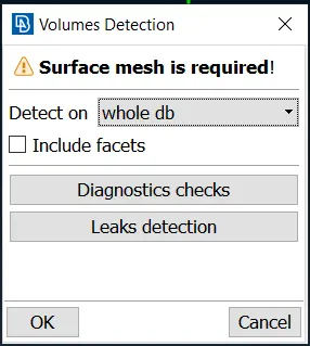
- A lot of volumes will be captured, but as we saw above the volume mesh need only where the fluid is going to be present and which other is only a thickness of our solid body. so deleting the unneeded volume detected in the whole database.
- Here the Tetra CFD mesh generations are done with a maximum growth rate of 1.2.
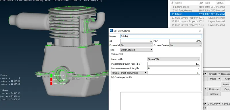
- Hence the Volume has been created for the following parts Engine block, Oil pan and Intake.
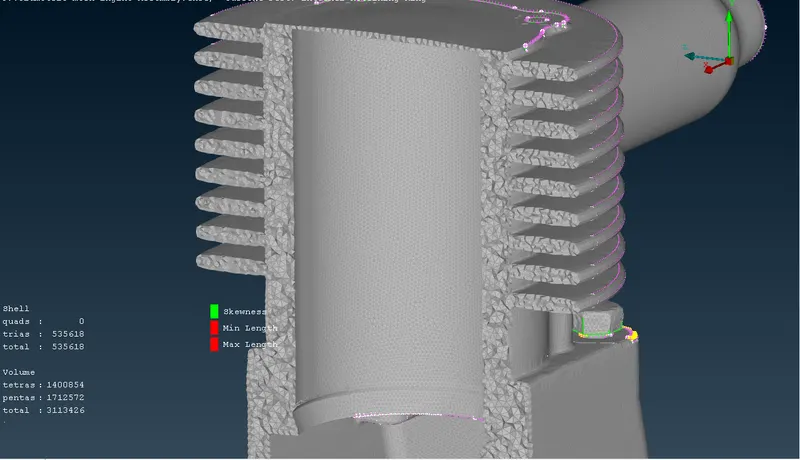
- Cross section of the Engine block.
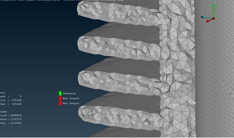
- Closed view of the engine block.
- Volumetric mesh on Oil pan.
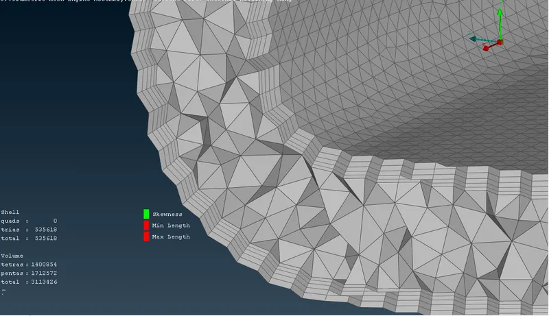
- Volumetric Mesh Visible in PIDs.
- The total no of tetras are 1249789.
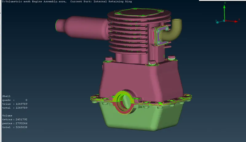
- All the off elements are cleared and volumetric meshing has been done according to the problem statement.
LEARNING OUTCOME:
- In this process, I have learned how to rectify geometry errors and mesh of a model and how to rectify errors in mesh and how those errors are to be corrected. learned naming section, surface correction and various tools for meshing.
- Different techniques of face-topo command.
- The meshing of various sub-parts is a good learning process.
- Learned to do Prism mesh layers.
- Volume meshing is an excellent learning outcome.
CONCLUSION:
- The given geometry is studied and a topological cleanup and surface meshing and volumetric meshing of the given geometry are carried out.
- Doing this project it helps to gain more about topological cleanup, constructing new surfaces, surface meshing and volumetric meshing by using different sets of tools in ANSA software.
- As we studied with fine mesh size, the accuracy increases but the time for calculation also increases so for all the parts and PIDS
- Volumetric mesh can be achieved only after creating surface mesh successfully, or else the geometry can give fatal errors while volume meshing. The overlapped surface can be deleted using the universal delete option.
- Unnecessary single and triple cons can be removed and edited using different tools such as cons project, topo, release and fine tools while geometry cleanup. Successful volumetric mesh can be achieved only after correct geometric cleanup and surface mesh.
- Hence all the problem statement has been achieved and the surface wrap, surface mesh, volumetric mesh and prism meshing.
UPLOADED MODEL:
https://drive.google.com/drive/folders/1rxPuQCEktL0OkVWmZvmjOEA_RNF4n91-?usp=sharing
- As the size of the model is too large to upload directly, the 'google drive' link is been shared to access the corrected model.
REFERENCE: