Project 1 _Creating an Architectural plan for the provided plot size and develop relevant basic structural drawings
AIM : To Design and Draft a layout of a residential building with the following details:
Plot Size: 60’x20’(18.3m x6m)
Orientation- Facing East
Develop the following:
1. Architectural Drawing (Floor Plan, Elevations, and Sections)
2. Structural Drawing (Column, Bean, Footing Plan)
COMMANDS USED MOSTLY
L - LENGTH
TR - TRIM
REC - RECTANGLE
O - OFFSET
F - FILLET
ARC - ARC
TEXT - FOR TEXT
DIM - MEASURING
SC - TO INCRESE OR DECRESE THE SCALE
EX - EXTENT
H - HATCH
Procedure:
1) set the units
type the "un" in command bar
select the 'decimal' and precition as '0.00' and unit scale in 'meters'
2)set the limits
type the limmax in command bar
set the limit to 1000,1000
type 'z' zoom (enter), 'a' all (enter)
3) type the xline and draw one vertical and horzontal line
4) trim the down and left hand side lines
5)offset 'o'
enter the value 18.3 (horizontally) and double enter 6 vertical line
trim the un required lines
6)in same way draw all the walls and trim unrequired lines by refering the rougth skech of you
7) draw the lines 'L' at required parts and join the lines by using command 'J'
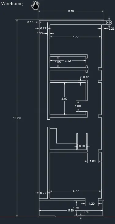
8)use the layers and apply doors, window,ventilaters,dimenstions
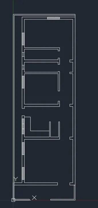
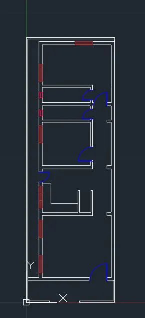
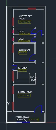
adjust all text by SCALE
now we are done with the plan
9) let as draw the elevation part now
by extending the lines from plan command 'EX'
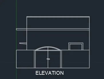
with the dimensions
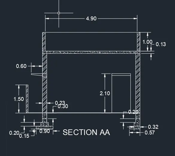
10) after that section is also drawn as with above dimension
apply the hatch to wall, beam,footing,ect..command 'H'
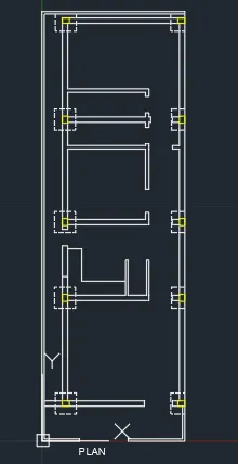
11)and final drawing look like this
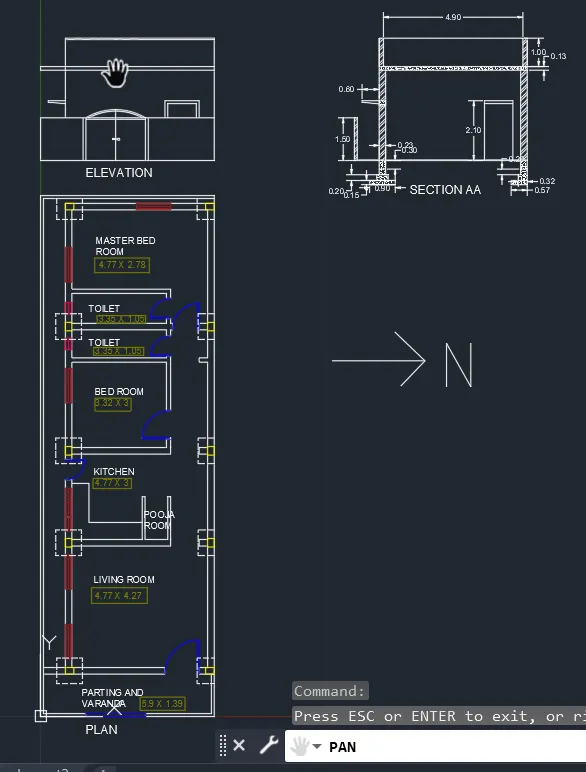
2Q)
12)KEEP ALL LAYER OFF EXCEPT THE SKELITION OF THE BODY(PLAN)
AGAIN TAKE NEW LAYER AS COLUMN AND DRW THE COLUMS SIZE IS 0.23*0.3 M
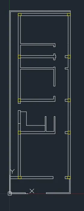
13) FOOTING AND BEAMS ARE ALSO MARED
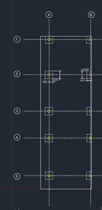
IT ALSO DONE
RESULT : FOR THE GIVEN PLOT 18.3*6 M PLAN,ELEVATION,SECTION,COLUMN,BEAM,FOOTING ARE SHOWN AND DRAWN IN AUTO CAD SOFEWARE.