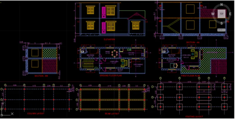
Project 1 _Creating an Architectural plan for the provided plot size and develop relevant basic structural drawings
EAST FACING RESIDENTIAL BUILDING
ARCHITECTURAL AND STRUCTURAL DRAWING
AIM
To create an Architectural plan for the provide plot size and develop relevant structural drawings using AutoCAD
INTRODUCTION
An architectural and structural drawing using AutoCAD is created by lines. The procedure and results should be written after creating an architectural and structural drawing
ARCHITECTURAL DRAWING
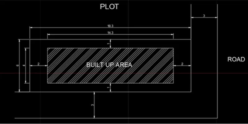
PLOT
AIM
To create a plot using AutoCAD
INTRODUCTION
The plot using AutoCAD is created by lines. The procedure and result should be written after creating the plot
PROCEDURE
- Open AutoCAD and set Units to meters and set Limits
- Draw a rectangular of size 14.3*4
- Draw another rectangle of 18.3*6 over the 1st rectangle
- Draw L shape on the right side to show the road facing having 3m distance from the plot
- Dimensions should be noted and Insert text using the text command
RESULT
The plot is created using Autocad and step by step procedure for the plot is also explained.
GROUND FLOOR
AIM
To create a ground floor plan using AutoCAD
INTRODUCTION
The ground floor plan should be created and the procedure and result should be written after creating in AutoCAD
PROCEDURE
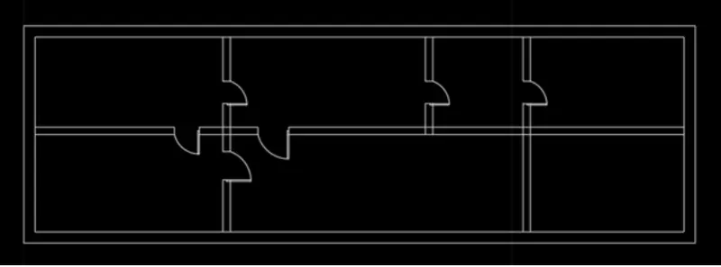
- Enter line command and use 0,0 as the first point
- Enter (@14.3,0) (@0,4) (@-14.3,0) (@0,-4) and close
- Using offset command draw wall thickness of 0.23m
- now offset 0.38 in the inner left side and 0.15m
- select 0.38m and offset line behind
- Select 4 as offset distance and offset 0.15 line behind
- Select 6 as offset distance and offset 0.15 line behind
- Select 4 as offset distance and offset 0.15 line behind
- Select 2 as offset distance and offset 0.15 line behind
- Select 2 as offset distance and offset 0.15 line behind
- TRim and delete unwanted lines
- Trim for door distance of the required size
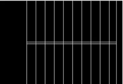
- Draw stairs of 9 rise using line and offset command
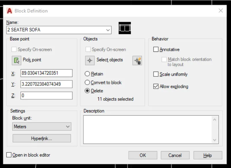
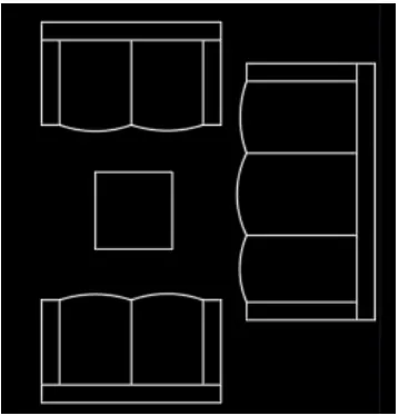
- Enter line command and select 2 seater and 3 seater sofa and arrange them as required in the design
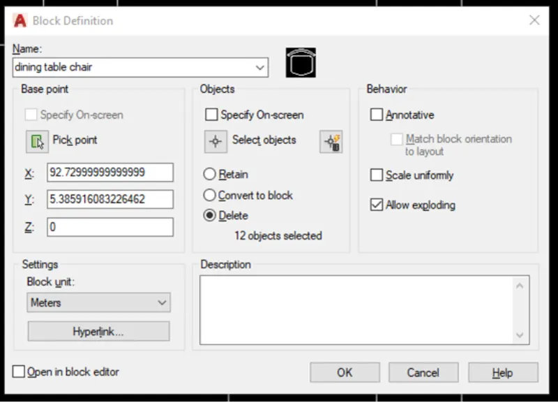
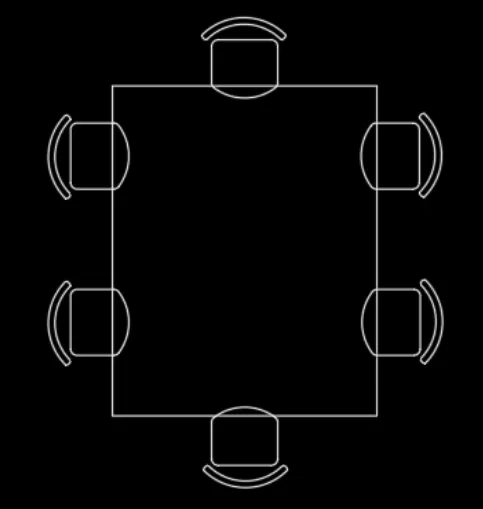
- Enter L command and select dining table and chairs according
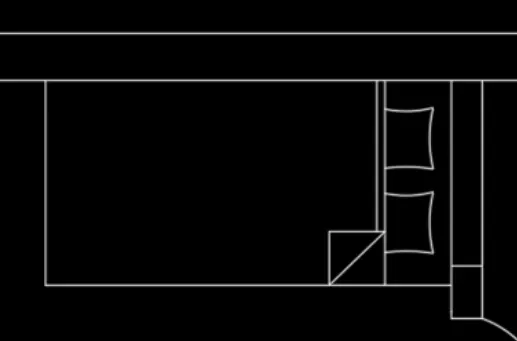
BED
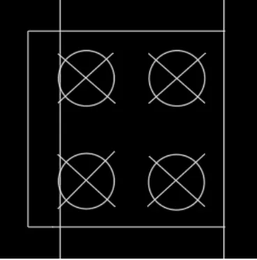
HUB (STOVE)
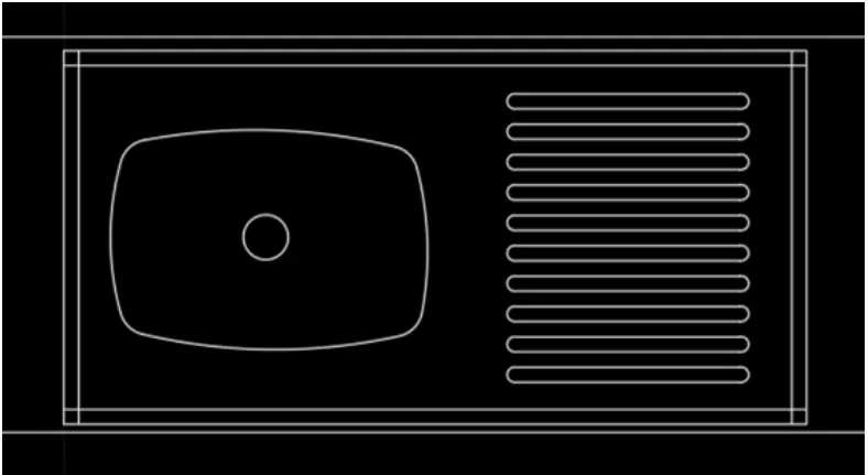
KITCHEN SINK
 '
'
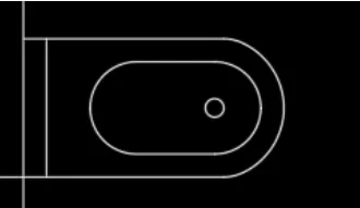
WASHBASIN

WATER CLOSET
- Arrange the components as required in the plan
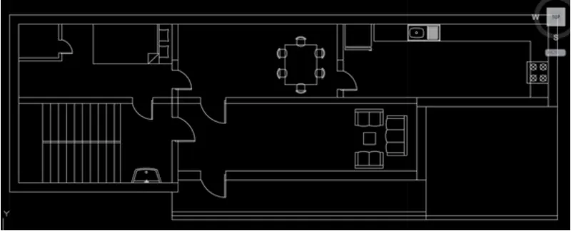
- Using hatch command Hatch brickwork
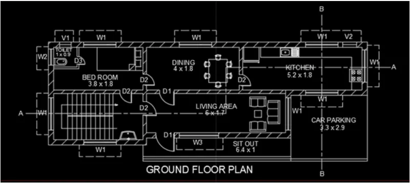
- Enter text command and apply text height as 0.2
- Using dotted lines section the plot horizontally and vertically
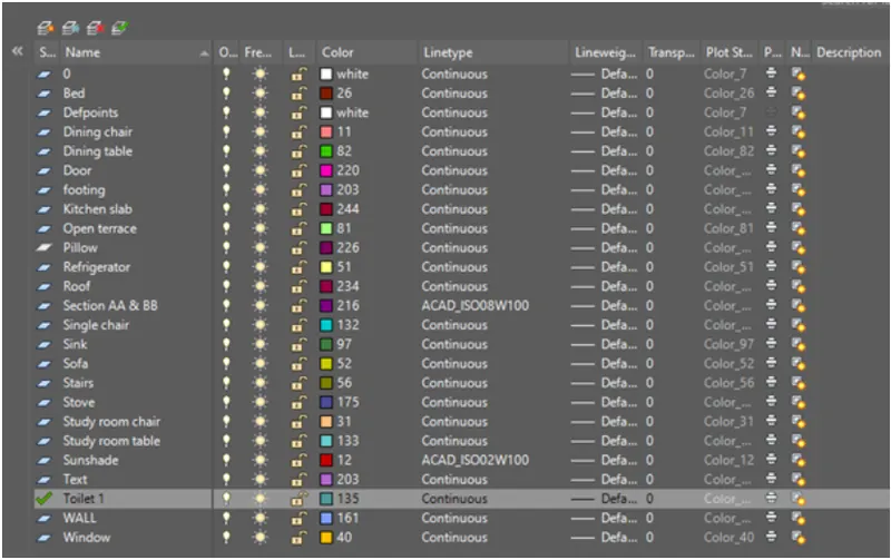
- Using layer command create layers for bed, dining table, chair, door, footing, pillow, tank, fridge, sink, sofa, stove chair, etc with different colors
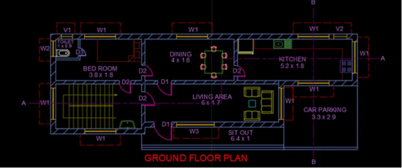
RESULT
The ground floor plan is created using AutoCAD
FIRST FLOOR PLAN
AIM
To create a first-floor plan using AutoCAD
INTRODUCTION
The first-floor plan should be created and the procedure and result should be written after creating in AutoCAD
PROCEDURE
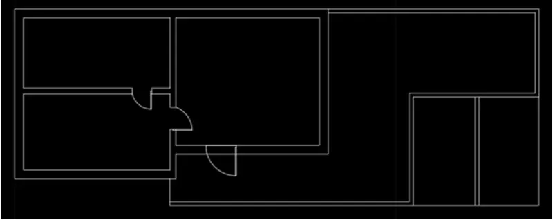
- Copy the ground floor plan after creating walls and doors
- Enter line command (@-3.3,0) (@0,-2.85) as next point
- Enter 1.57 offset distance and trim unwanted lines
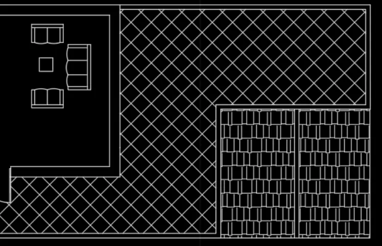
- Using hatch command hatch open terrace
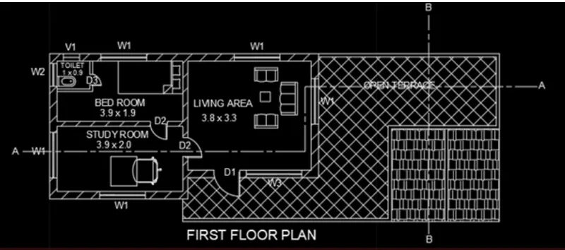
- Copy section AA BB and place it
- Using text command insert text wherever needed
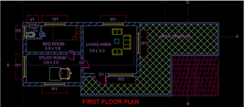
- Click layers, select required names and their colors, select object and place it
RESULT
The First-floor plan is created using AutoCAD
ELEVATION
- Enter XL line and extend wall, window, and doors from the ground
- Draw a baseline
- Measure slab distance as 0.5 and height of building 3m
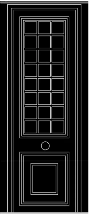
- Draw doors and windows and Trim unwanted lines
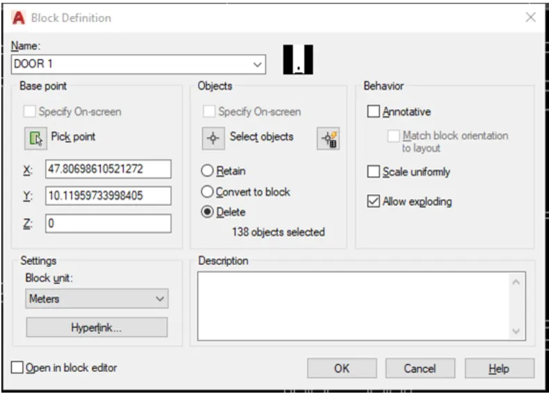
DOOR
WINDOW
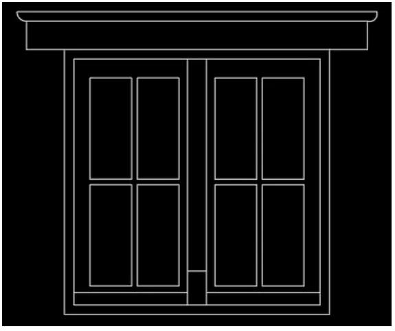
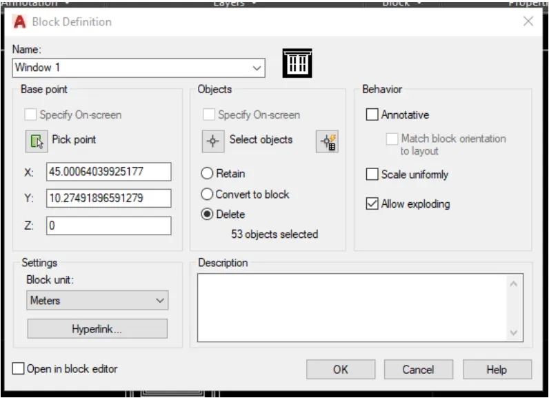
- Enter MI in the comment box click at the middle point and connect it at another point
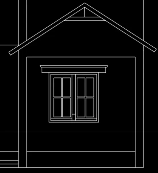
- Draw sunshade and copy it where ever required
- Using hatch command hatch the required area
- Insert text wherever required
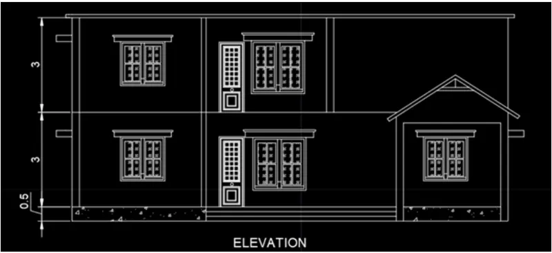
- Click layer property and select window, door, sunshade, roof, text, and dimension
- Apply appropriate colors
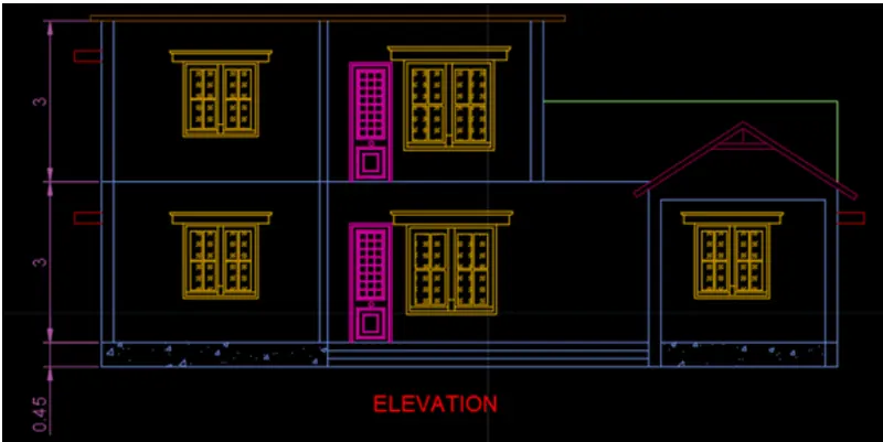
RESULT
The elevation plan is created using AutoCAD
SECTION AA
AIM
To create section AA using AutoCAD
INTRODUCTION
A section AA is created using AutoCAD and the result should be written after creating section AA
PROCEDURE
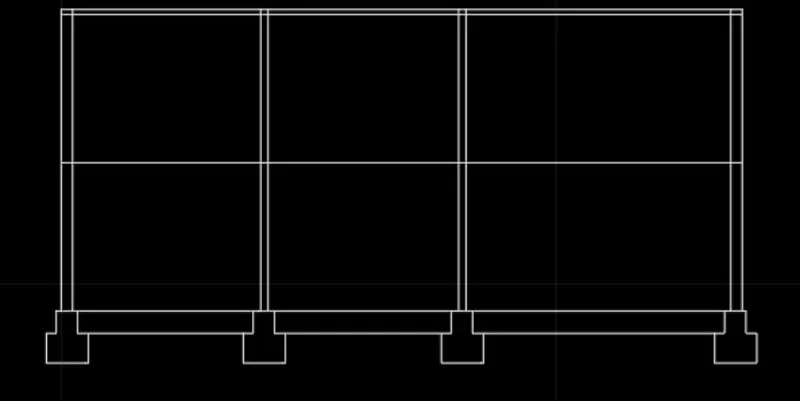
- Enter XL line and extend the line in the horizontal and vertical direction
- Draw a baseline and marks required lines
- Trim unwanted lines
- Using offset command draw room, wall, door, windows, etc
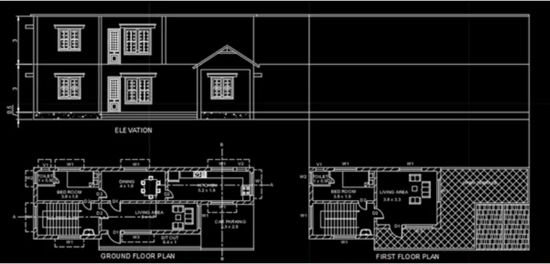
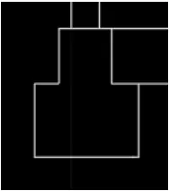
- Click lower left outside line corner
- Enter (@-0.1,0) (@0,-0.45) (@-0.2,0) (@0,-0.6) (@0.86,0) (@0,0.6) (@0.2,0) (@0,0.45) and close

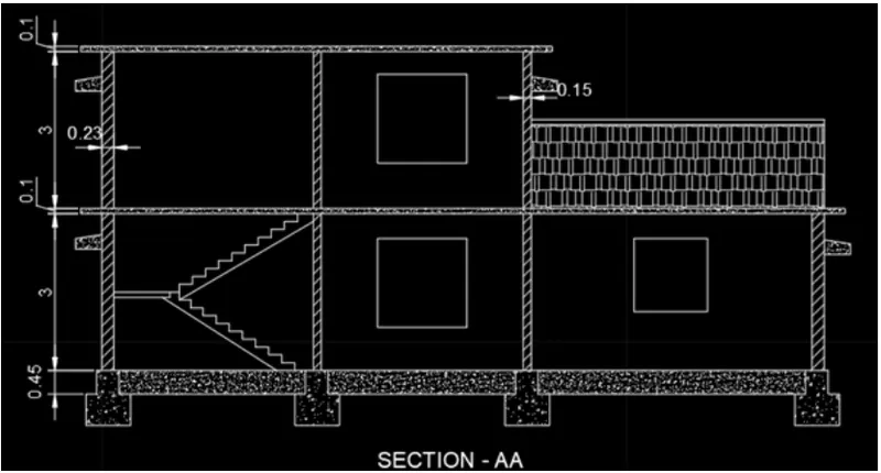
- Draw stairs of required length and width
- Place the object at the required place
- Use hatch command and hatch wherever required
- Insert the text of text height 0.2m
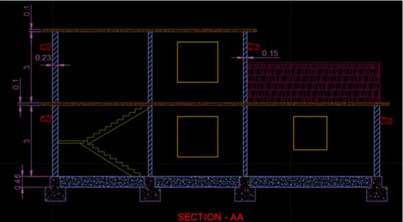
- Using layer command layers are inserted
RESULT
The step by step procedure of creating section AA is created using AutoCAD
SECTION BB
AIM
To create a section BB using AutoCAD
INTRODUCTION
A section BB is created using AutoCAD and the result should be written after creating section AA
PROCEDURE
- Enter XL command and extend line horizontal and vertical line
- Draw windows, doors, walls, the footing of the required size
- Trim unwanted lines
- Using Hatch command hatch the required area
- Insert text and Dimensions using respective command
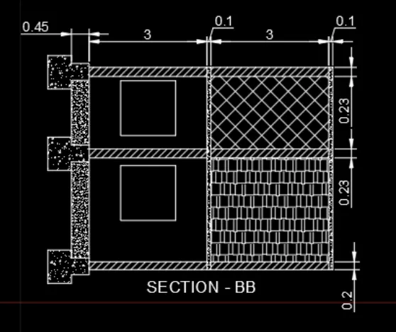
- Using layer command layers are inserted
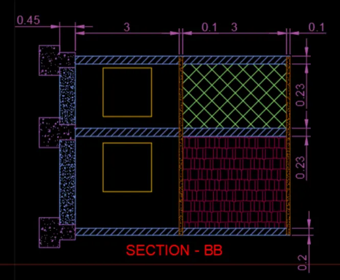
RESULT
Section BB is created using AutoCAD
STRUCTURAL LAYOUT
COLUMN LAYOUT
AIM
To create column layout using AutoCAD
INTRODUCTION
A column layout is created using AutoCAD and the procedure and result should be written after creating column design
PROCEDURE
- Copy the plan to delete the unwanted design
- Using the Array command create column of (0.23,0.23)
- Mark the layers in red color
- Enter line type as hidden line
- Enter text and dimensions using the required dimension
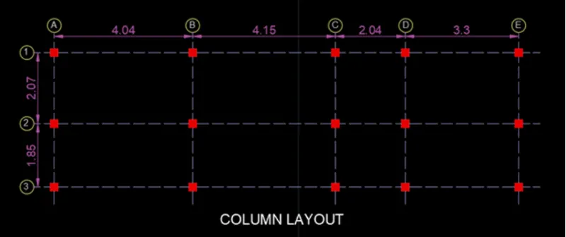
RESULT
The column details are created as required
BEAM LAYOUT
AIM
To create beam layout using AutoCAD
INTRODUCTION
A beam layout is created using AutoCAD and the procedure and result should be written after creating column design
PROCEDURE
- Copy the column layout
- Join the outer lines
- Show beam design
- Trim unwanted lines
- Change line type
- Insert text and Dimensions using respective command
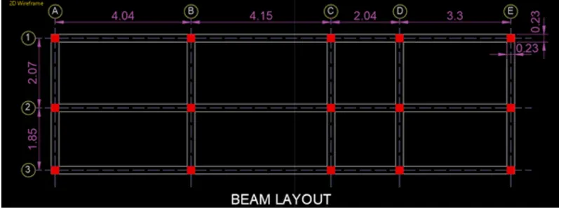
RESULT
The beam layout is created using AutoCAD
FOOTING LAYOUT
AIM
To create footing layout using AutoCAD
INTRODUCTION
A footing layout is created using AutoCAD and the procedure and result should be written after creating column design
PROCEDURE
- Copy column layout
- Draw a rectangle of size (1.2,1.2)
- Draw another rectangle of size (3,3)
- Now copy and paste the footing of required areas
- Trim unwanted lines
- Change line type
- Insert text and Dimensions using respective command
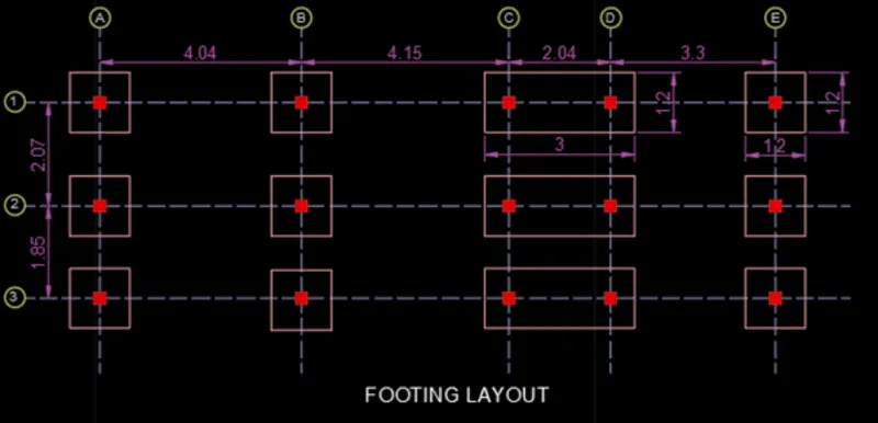
RESULT
The footing details are created and shown
ARCHITECTURAL AND STRUCTURAL DRAWING
RESULT
The combined architectural and structural drawing is created