Project 1 _Creating an Architectural plan for the provided plot size and develop relevant basic structural drawings
- PROJECT : CREATING AN ARCHITECTURAL PLAN FOR THE PROVIDED PLOT SIZE AD DEVELOPED RELEVANT BASIC STRUCTURAL DRAWINGS
- AIM : DRAW THE BUILDING ARCHITECTURAL PLAN HAVING PLOT SIZE 60'X20' (18.3 M X6 M) AND DEVELOP THE STRUCTURE :
- ARCHITECTURAL DRAWINGS :
- Site plan
- ground floor plan
- first floor plan
- elevation
- section plan
- STRECTURAL DRAWING :
- column layout plan
- beam layout plan
- footing layout plan
- DIMENSIONS :
- external wall : 230 mm
- internal wall : 150
- window : 1000x2000
- Door 1 :1000x2000
- Door 2 : 900 x2000
- PROCEDURE :
- Click on autocad aplication
- command : QNEW
- select the metric system
- click on ADVANCE SETTING
- Unit : decimal precision 0
- click on NEXT
- angle : decimal precision 0
- angle measure : EAST
- Angle direction : counter clockwise
- area : 100x100
- press : ENTER
- command : UN
- select decimal
- unit mm
- press : ENTER
- SITE LAYOUT PLAN
- command : REC (for rectangle )
- select starting point
- click on DIMENSION
- length :18300
- width : 6000
- command : o (for ofset )
- distance : 2000
- command : o
- distance : 1000
- command : o
- distance : 3000
- press : enter
- command : TR ( for triam )
- triam the extra part
- command : o
- distance : 4000
- for ROAD section
- command : BREAKLINE
- for for road as show in drawing
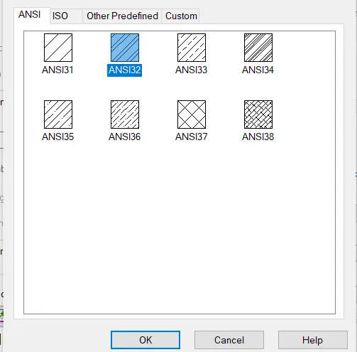
- command : hatch
- patern :ANS132
- command : DIMLIN ( for dimension )
- give the dimension to the plan
- command : MTEXT ( for text )
- give the text to the plan
- press : ENTER
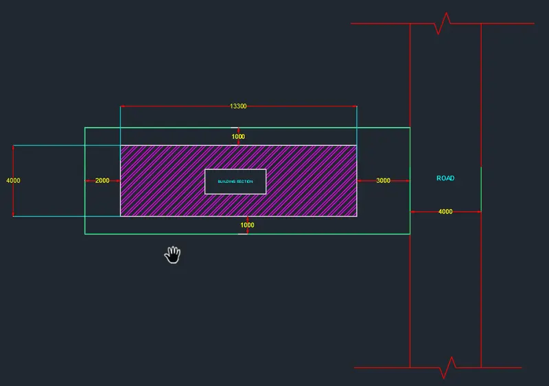
- AREA FOR DEVELOPMENT : 13000 X 4000
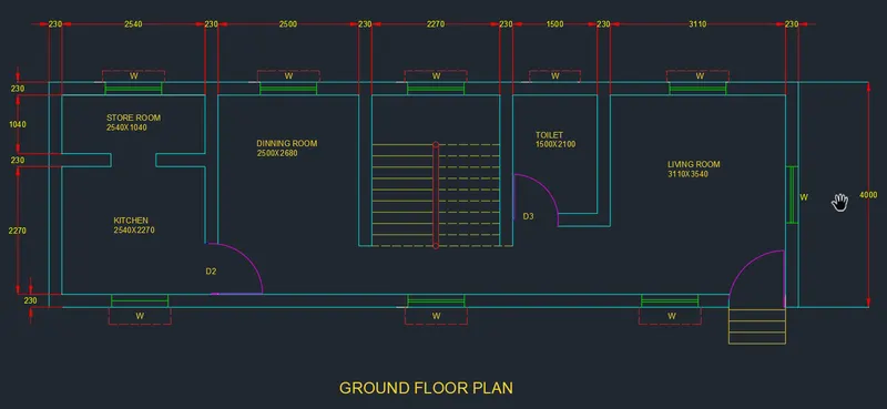
- GROUND FLOOR PLAN
- PROCEDURE :
- command : XL
- mark horizontal and vertical lines by using xl command
- command : o ( for ofset )
- distance 230 for wall thickness on both horizontal and vertical
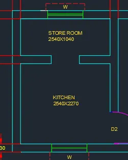
- store room :
- command ofset
- distance 2540 x 1040 and give the 230 mm ofset wall wall
- for kitchen :
- command : o ( for ofset )
- distance : 2540 x 2270
- and giive 230 mm ofset wall thickness
- command : TR ( for triam )
- triam the extra part
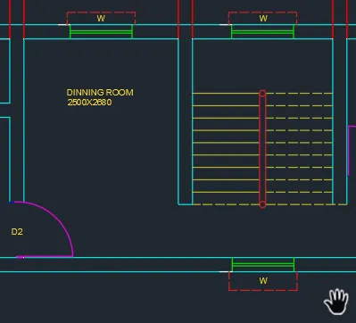
- for dinning room :
- command : o (for ofset )
- dimension : 2500 x 2880
- again command ofset and give 230 ofset for wall thickness
- command : TR (FOR TRIAM )
- triam the extra part
- for staircase
- command :o (for ofset )
- distance : 2270 and 230
- command : o
- distance 200 for rise and treads
- for toilet
- command : o (for ofset )
- distence 1500x2100
- and give the 230 mm ofset for wall thickness
- command : tr (for triam )
- distance : 3110 x 3540
- command : o (for ofset )
distance 230 mm - command : TR ( for triam )
- triam the extra part
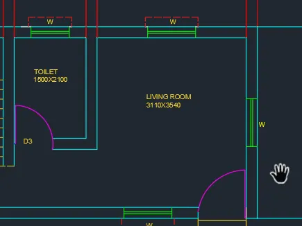
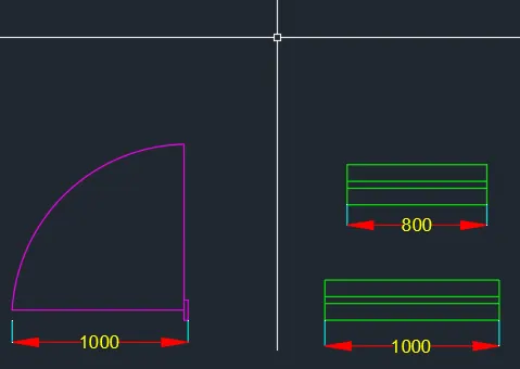
- for doors and window
- command : REC (for rectangle )
- make small rectange
- command : circle
- mode : 2 point circle
- make make circle
- command : TR (for triam )
- triam extra part
- for window
- put object snap on
- click on midpoit and mark a line
- take ofset of that line distance 1000
- and draw the window
- take centerpoit of that line and mark 2 horizontal line by using ofset command
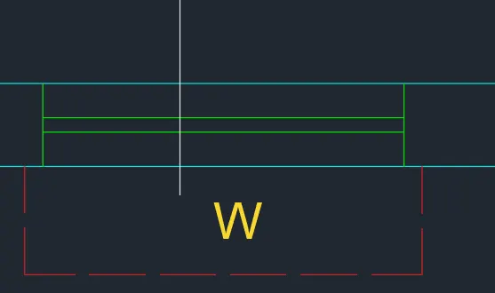
- command : linetype
- click on load
- put ISO DASH line
- make it current
- press : ENTER
- and mark a line over window
- command : DIMLIN
- for dimension
- give the dimension
- command : DIMCONTINUE
- and give the dimension for all units
- command : MTEXT
- and give the text
- press : enter
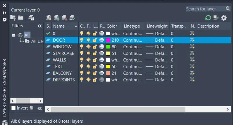
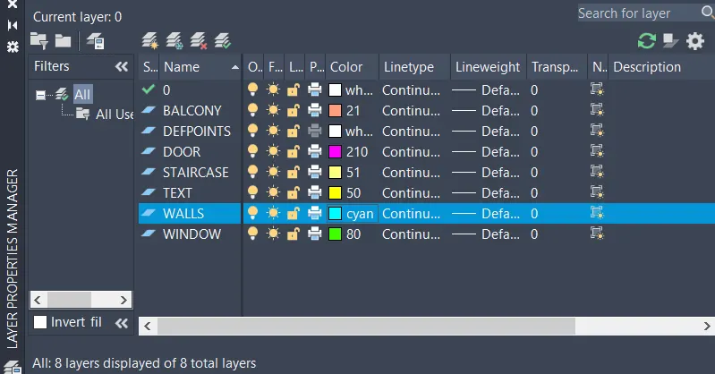
- go to the layer properties
- and create a layers
- as show below
- RESULTS
- COMMAND USED
- START : QNEW
- UNITS : UN
- LIMETS : LIMMAX
- COMMAND : XL
- LINE : L
- RECTANGLE : REC
- OFSET : O
- TRIAM : TR
- TEXT : MTEXT
- DIMENSION : DIMLIN
- DIMCONTINUE
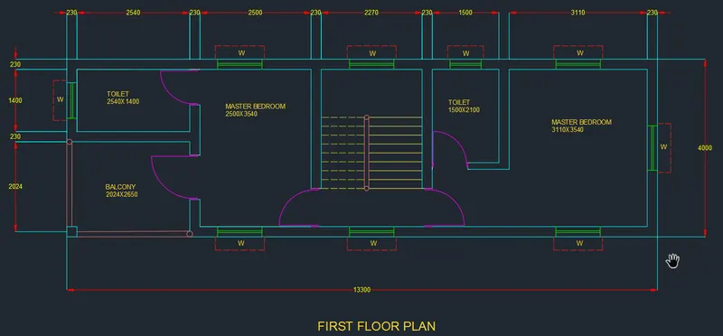
- FIRST FLOOR PLAN :
- PROCEDURE :
- command : xl
- and make the horizontal and vertical line
- command : ofset and give 230 mm ofset for wall thickness
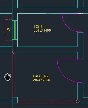
- for toilet
- used ofset command
- dimension : 2040 x 1400
- command : ofset and make 230 mm ofset for wall thickness
- for balcony
- command : ofset
- distance 2024 x 2650
- mark 230 mm ofset for wall
- command : TR (for triam )
- triam the extra part
- put object snap mode on
- take midpoit of 230 mm vertical line
- and mark the line for balconey portion
- command : circle
- mode : 2 point circle
- and draw the circle
- for balconey
- for masterbedroom
- command : ofset
- distance : 2600 x 3640
- command : ofset
- distance 230 mm for wall thickness
- command : tr (for triam )
- triam the extra part
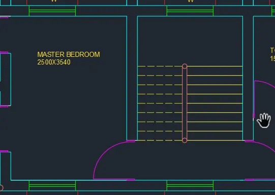
- for staircase
- command : ofset
- distance : 2270 then 230
- object snap on
- take the midpoint of line 2270
- and mark the vertical line
- give the ofset having distance 100 mm for this vertical line
- command : ofset
- distance 200 for rise and treads
- click on MULTIPLE
- AND GIVE 9 NO OFSET LINE
- command : line type
- click on LOAD
- select ISO DASH line
- put it current
- command : ofset
- distance : 200
- select MULTIPLE
- and give 9 nos ofset line
- command : TR ( for triam )
- triam the extra portion
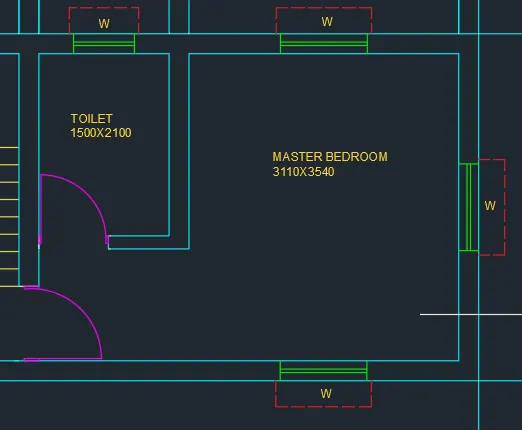
- for toilets
- command : ofset
- distance : 1500x2100
- also give 230 mm ofste for wall thickness
- command : TR (for triam )
- triam the extra part
- for master bedroom
- distance 3110 x 3540
- the give 230 mm ofset for wall
- for doors and window
- command : REC (for rectangle )
- make small rectange
- command : circle
- mode : 2 point circle
- make make circle
- command : TR (for triam )
- triam extra part
- for window
- put object snap on
- click on midpoit and mark a line
- take ofset of that line distance 1000
- and draw the window
- take centerpoit of that line and mark 2 horizontal line by using ofset command
-
- command : linetype
- click on load
- put ISO DASH line
- make it current
- press : ENTER
- and mark a line over window
-
- put the doors and windows over walls as show in plan
- command : DIMLIN (for dimension )
- give the dimension
- command : DIMCONTINUE
- and give the dimension to all units
- then ,
- command : MTEXT ( for text )
- write the text over all units
- press : ENTER
- select the lines
- go to the layer propertice and aply particular line by layer
- as per given below
- press : ENTER
- RESULTS :
- COMMAND USED :
- LINE : L
- OFSET : O
- TRIAM : TR
- COMMAND : XL
- CIRCLE : C
- RECTANGLE : REC
- TEXT : MTEXT
- DIMENSION : DIMLIN , DIMCONTINUE
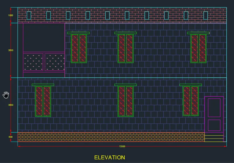
- ELEVATION
- PROCEDURE :
- command : xl
- mark horizontal and vertical line by using xl command
- command : o (for ofset )
- distance : 13300 give vertical distance
- command : o (for ofset )
- distance : 600 horizonticaly
- then give the ofset distance 3500
- again give ofset distane 3500
- and then give 1000 for parapet wall
- command : TR (for triam )
- triam the extra lines
- then take the refrance line for windows and balcones from ground floor plan
- command : REC (for rectangle )
- click on DIMENSION
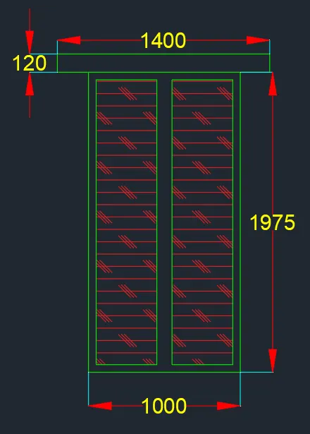
- length :1400
- width : 120
- this rectangle paced over window
- then ,
- command : REC ( for rectangle )
- click on DIMENSION
- LENGTH : 1000
- width : 1975
- command : REC (for rectangle )
- click on dimension
- length :400
- width : 1870
- this rectangle placed in window
- command : MR (for mirror )
- put object snap ON
- click on inner rectangle
- selct midpoint and mirror thre object
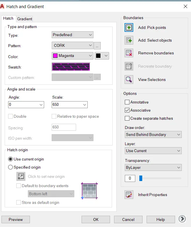
- commnd : hatch
- hatch setting given below
- apply hatch to all window
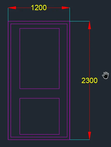
- for door
- mark the refrance line from ground floor plan
- command : REC ( FOR RECTANGLE )
- select the start point
- click on DIMENSION
- length : 1200
- width : 2300
- command : o (for ofset )
- distance 50
- select the rectangle
- and mark the internal ofset of rectangle
- the command : REC
- ang draw the 2 rectangle as show on fig
- for parapet wall
- command : REC (FOR Rectangle )
- select the starting point
- click on dimension
- length " 250
- width : 500
- mark horizontal 2 lines with referance to this rectangle
- command : AR (for array )
- select the object
- click on path
- the click on that horizontal lines
- no of object is array is 9
- press enter
- command : TR (for triam )
- triam the extra lines
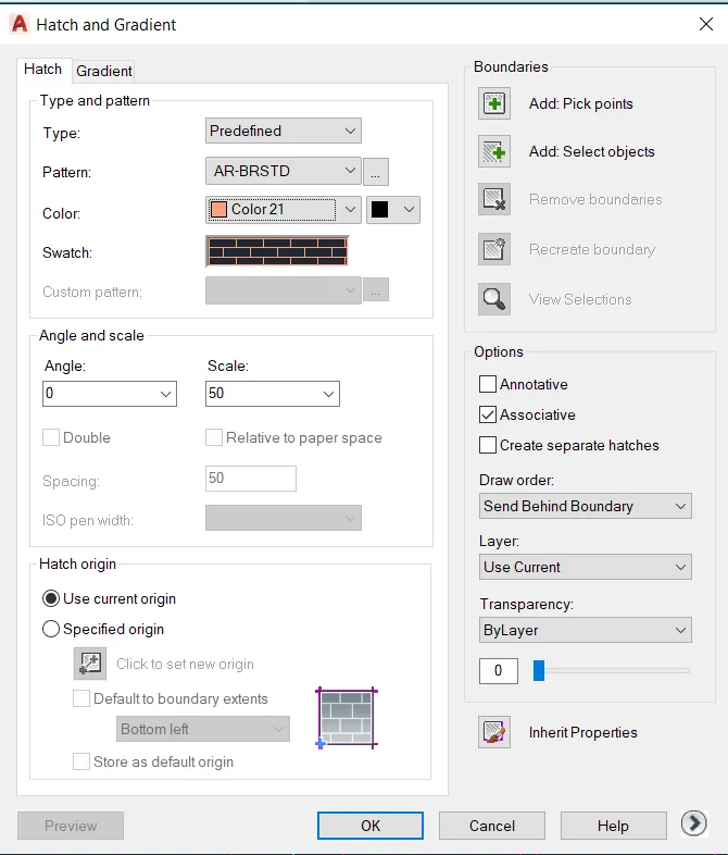
- command : HATCH
- hatch setting given below
- for balcony
- mark line with refrance to ground floor plan
- command : TR (for triam )
- mark lines of balconey after that triam the extra
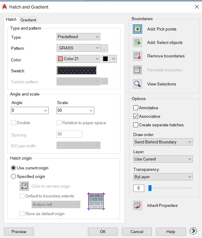
- command : hatch
- hatch seating given below
- for walls
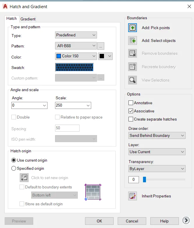
- command : hatch
- hatch eating is given below
- go to the layer properties
- and create the layers
- as shown below

- command : DIMLIN (for dimension )
- give the dimension
- command : DIMCONTINUE
- then
- command : MTEXT (for text )
- give the text to the plan
- RESULTS :
- COMMAND USED :
- LINE : L
- RECTANGLE : REC
- OFSET : O
- TRIAM : TR
- ARRAY : AR
- COMMAND : HATCH
- DIMENSION : DIMLIN , DIMCONTINUE
- TEXT : MTEXT
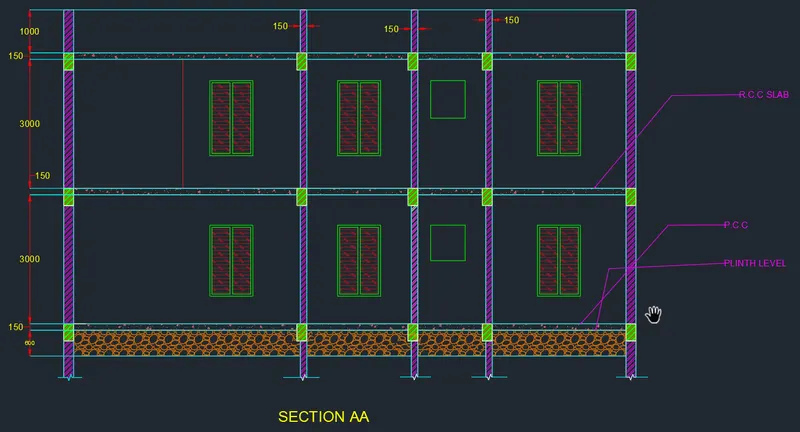
- SECTION PLAN :
- PROCEDURE :
- take the refrence line of first floor plan vertically
- command : L ( For ine )
- mark horizontal line over vertically line
- press : ENTER
- command : O (for ofset )
- distance 1000
- then mark 150 mm ofset line horizontically
- then mark 3000 mm ofset line
- then 150 mm ofset line
- then 3000 mm ofset line
- mark 150 mm ofset line horizontically by using ofset command
- then mark the 600 mm ofset line horizontically
- command : TR (for triam )
- triam the extra lines
- then mark the window by projecting the window from frist floor plan
- for window
- command : REC (FOR RECTANGLE )
- Click on DIMENSION
- length : 1000
- width : 1745
- again
- command : REC (for rectangle )
- click on dimension
- length : 420
- width :1645
- placed this rectangle in largr rectangle
- command : MR (FOR MIRROR )
- put object snap on
- Select the object
- click on midpoint
- and mirror this object
- command : HATCH
- hatch seating given below
-
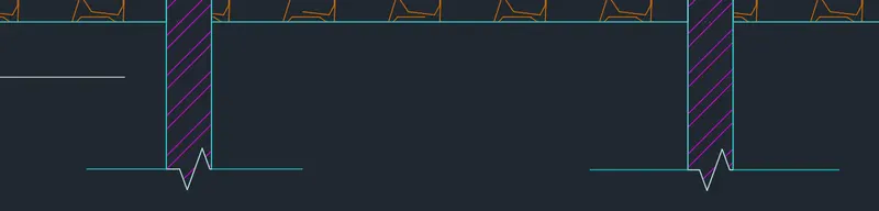
- command : BREAKLINE
- put object snap on
- mark the line over wall section
- click on midpoint
- and break the line
- for column
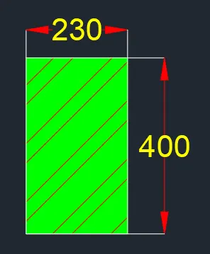
- command : REC (for rectangle )
- select the starting point
- click on DIMENSION
- length : 230
- width : 400
- command : HATCH
- And give the hatch to the portions
- hatch setting given below
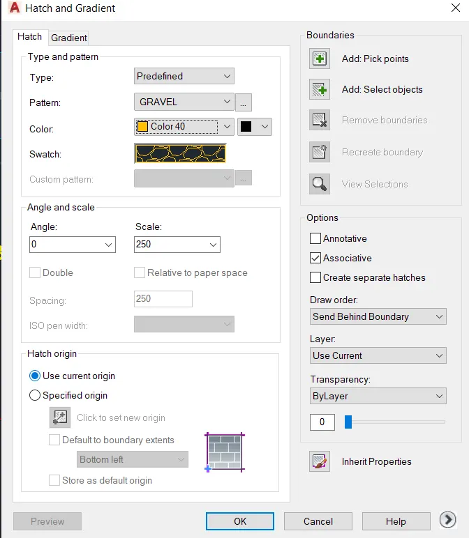
- FOR sub structure
- command :HATCH
- hatch setting given below

- Command : DIMLIN (for dimension )
- give the dimension
- command : DIMCONTINUE
- then , command : MTEXT
- give the al text
- press : ENTER
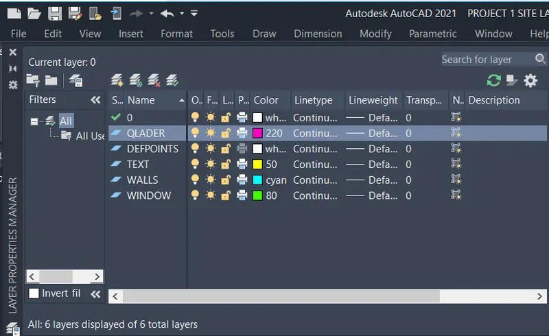
- GO to the layer properties
- create a new layer
- created layer snown below
- RESULTS :
- COMMAND USED :
- LINE : L
- RECTANGLE : REC
- TRIAM : TR
- COMMAND : HATCH
- BREAKLINE
- OFSET : O
- DIMENSION : DIMLIN , DIMCONTINUE
- TEXT : MTEXT
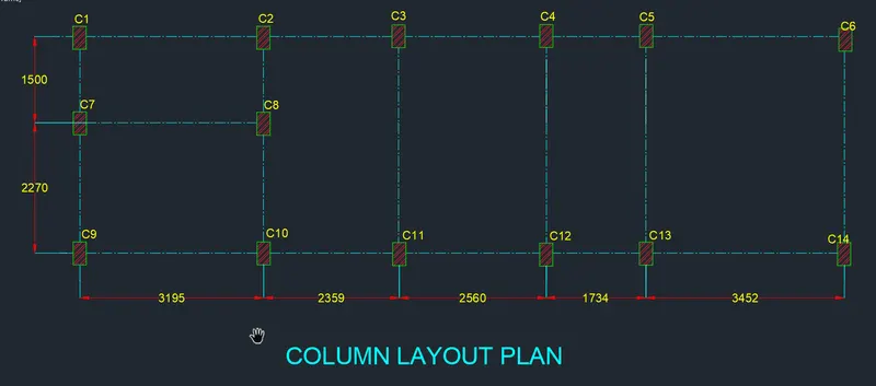
- COLOUMN LAYOUT PLAN :
- PROCEDURE :
- take the refrance line of ground floor plan
- the go the line type
- select the ISO LONG DASH SHORT DASH LINE
- make it current
- click on OK
- go the the anotation tab
- click on center line option
- and mark the centerline of all walls
- after marking the centerline
- command : TR (for triam )
- and triam the outer walls
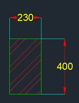
- command :REC ( for rectangle )
- click point where column is place
- click on DIMENSION
- length :230
- width : 400
- in this way placed all columns where requried
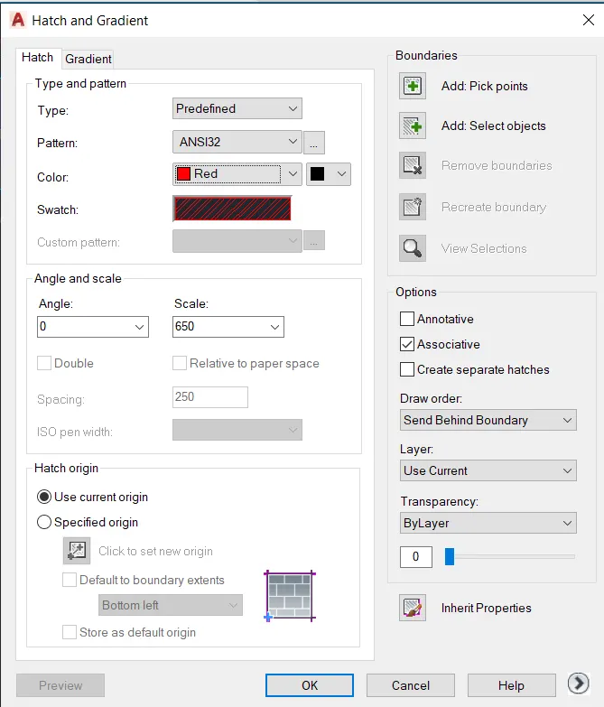
- comman : hatch
- and give the hatch to the all columns
- hatch patern shown below
- command : DIMLIN (for dimension )
- give the dimensions
- command : DIMCONTINUE
- press : enter
- then, command : MTEXT (for text )
- write all text in plan as shown below
- press : ENTER
- RESULTS :
- COMMAND USED :
- LINE : L
- RECTANGLE : REC
- HATCH
- QLADER
- CENTERLINE COMMAND
- MTEXT
- DIMLIN , DIMCONTINUE
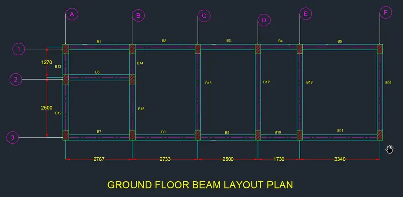
- GROUND FLOOR BEAM LAYOUT PLAN
- PROCEDURE
- take the reftance line of ground floor plan
- command : TR (for triam )
- triam the extra lines
- then,
- go to the anotation tab
- click on centerline
- mark centerline over plan
- for column ,
- command :REC
- click on point where column are show
- click on DIMENSION
- length : 230
- width : 250
- and place all column over plan
- command : HATCH
- And give the hatc to the all columns
- hatch setting given below
-
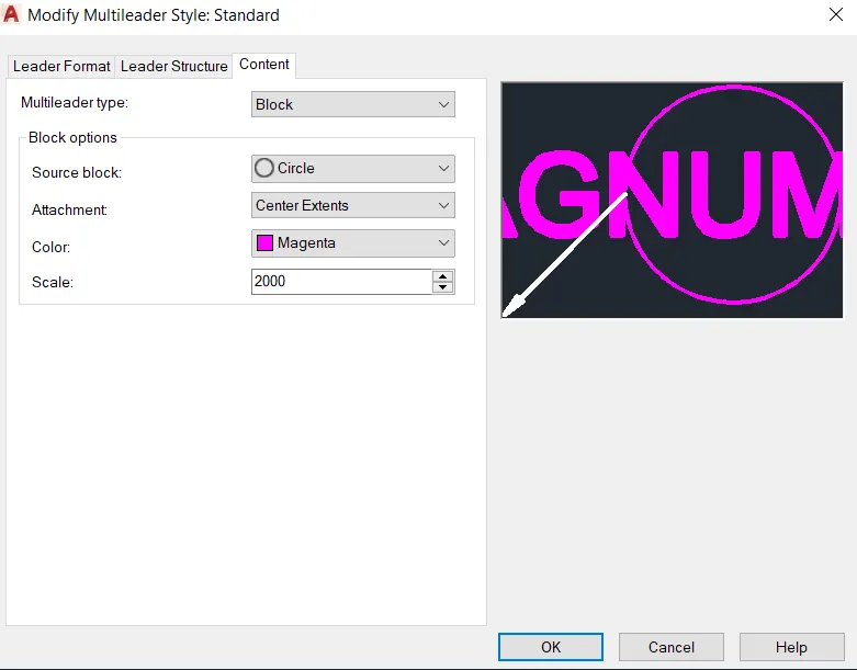
- then go to the anotation tab
- click o LEADERS
- select modify option
- click on CONTENT
- select BLOCK option
- source of block is CIRCLE
- Press : OK
- put it current
- and give the nos of all beams in pln as shown in plan
- command MTEXT (for text )
- write the text and give the numbers to beam
- command : DIMLIN (for dimension )
- give the dimensions
- command : DIMCONTINUE
- go to the layer propertices
- create the layers
- layers created as shown below
-
- RESULTS :
- COMMAND USED :
- LINE : L
- RECTANGLE : REC
- QLADER
- TRIAM : TR
- TEXT : MTEXT
- DIMENSIONS : DIMLIN , DIMCONTINUE
- FOOTING LAYOUT PLAN
- PROCEDURE :
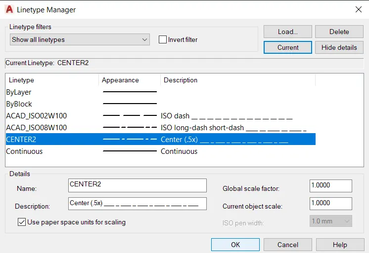
- go to the line type
- click on load
- click on CENTER2 line
- make it current
- press :ok
- take the refrence line of ground floor plan
- command : TR (for triam )
- triam the extra lines
- fo to the anotation
- click on CENTERLINE
- and give the centerline
- triam the outer lines
- command : REC (for column )
- select the point where rectangle is requried
- click on DIMENSIONS
- length : 30
- width : 400
- press : enter
- for footing
- command : O (for ofset )
- distance : 500
- and give the ofset for footing to the column
- commad : DIMLIN (dimension )
- give the dimensions
- command : DIMCONTINUE
- and give all dimension to the plan
- command : MTEXT (for text )
- write the text
- press : ENTER
- RESULTS :
- COMMAND USED :
- LINE : L
- OFSET : O
- TRIAM : TR
- RECTANGLE : REC
- TEXT : MTEXT
- DIMENSION : DIMLIN , DIMCONTINUE
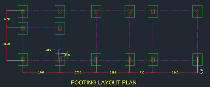
- FINAL RESULTS :
- ARCHITRTURAL PLAN
- SITE PLAN :
-
- GROUND FLOOR PLAN
-
- FIRST FLOOR PLAN :
-
- ELEVATION :
-
- SECTION PLAN
-
- STRUCTURAL PLAN :
- COLUMN LAYOUT PLAN :
-
- GROUND FLOOR BEAM LAYOUT PLAN :
-
- FOOTING LAYOUT PLAN :