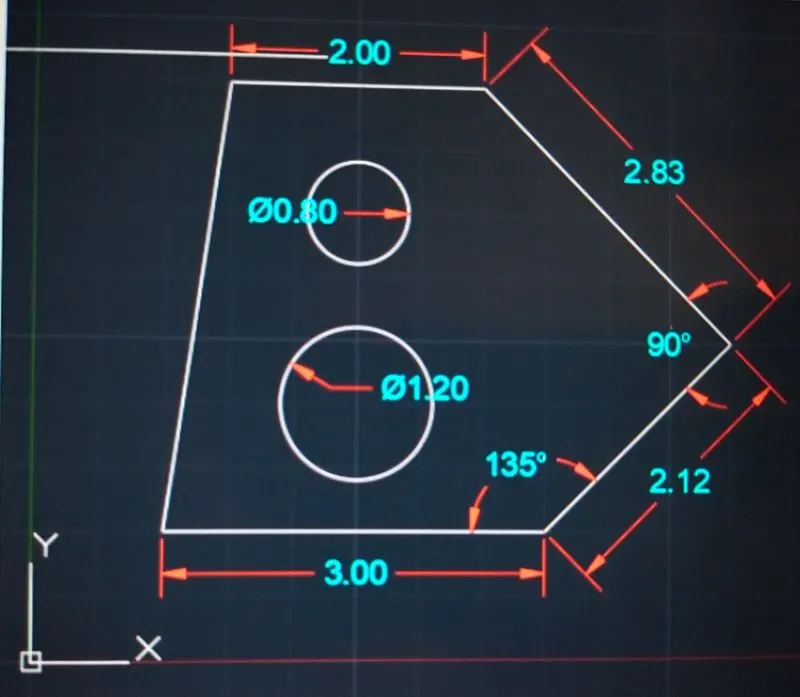
Drafting of various geometries using Chamfer, Fillet tool in AutoCad
- DRAFTING OF A VARIES GEOMETRIES DRAWINGS USING CHAMFER , FILLET AND OTHER TOOLS IN AUTOCAD .
- SOFTWARE USED : AUTODESK AUTOCAD 2021
- AIM : TO DRAW THE GIVEN DRAWING BY USING AUTOCAD SOFTWARE :
- PROCEDURE :
- first the open the software
- give the command QNEW and press the ENTERE key
- click on imperical templete
- select ADVANCE SETUP
- unit : decimal , precision :0.00
- angle :decimal degree , precision :0.00
- angle measure : East
- angle direction : closkwise
- area : 20*20
- and finished , lets start
- command :PL (for polyline )
- starting point :1,1
- @3<0
- @2.12<45
- @2.83<135
- @2<180
- then closed
- after that ,
- object snap :ON
- in object snap slect the MIDPOINT AND ENDPOINT option press OK and closed the dialog box .
- command :L (line )
- starting point : midpoint of line (@3<0)
- then ,@1<90
- press ENTER
- Command : C ( circle )
- starting point : endpoint of line (@1<90
- press :DIAMETER
- give the diameter :1.20 press :ENTER
- delete :line (@1<90)
- then ,
- command :L (line )
- starting point :midepoint of line (@3<0)
- @2.50<90
- press ENTER
- command :C (circle )
- starting point : endpoint of line (@2.50<90)
- press :DIAMETER ,
- give the diameter 0.80
- delete : line (@2.50<90)
- give the dimensition of all point
- go to the PROPERTIES dilog box
- change the text colour :sky blue
- arrow colour :red
- finished
- RESULTS :
- BELOW DIAGRAM SHOW THE RESULTS OF ABOVE PROCEDURE :
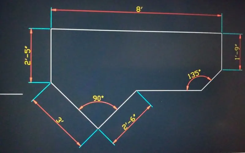
- AIM :DRAW THE FOLLOWING FIG BY USING AUTOCAD SOFTWARE :
- PROCEDURE :
- first the open the software
- give the command QNEW and press the ENTERE key
- click on imperical templete
- select ADVANCE SETUP
- unit : Engineering , precision :0'-0"
- angle :decimal degree , precision :0.00
- angle measure : East
- angle direction : counterclockwise
- area : 20*20
- and finished , lets start
- object snap : ON ,ENDPOINT AND MIDPOINT
- command :L (line )
- @2'-6"<45 degree
- press :ENTER
- command :L(line )
- starting point : first point of line (@2'-6"<45)
- @3'<135
- @2'-5"<90
- @8'<0
- @1'-9"<270
- press : ENTER
- Command :L (for line )
- starting point : endpoint of line (@2'-6"<45)
- give distance @3'1"<0
- joint the endpoint of line (@1'-9")
- press :ENTER and finished
- give all dimensition
- go to the properties dialog box
- change the colour of text and arrow
- text colour :yellow
- arrow colour :red
- RESULTS :
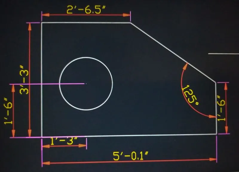
- AIM : DRAW THE FOLLOWING DIAGRAM BY USING VARIOUS COMMAND AND TOOLS IN AUTOCAD :
- PROCEDURE :
- first the open the software
- give the command QNEW and press the ENTERE key
- click on imperical templete
- select ADVANCE SETUP
- unit : Engineering , precision :0'-0"
- angle :decimal degree , precision :0
- angle measure : East
- angle direction : counterclockwise
- area : 20*20
- and finished , lets start
- command :L (line )
- @3'-3.0"<90
- @2'-6.5"<0
- press :ENTER
- command :L (line )
- objest snap :ON , endpoint and midpoint
- starting point :first point of line (@3'-3.0"<90)
- @5'-0.1"<0
- then joint the endpoint of line (2'-6.5"<0) by using object snap
- press :enter
- command :L (for line )
- starting point :first point of line (3'-3.0"<90)
- @1'-3.0"<0
- @1'6.0"<90
- press enter
- command :C (for circle )
- starting point :endpoint of (@1'-6.0<90) by using object snap
- give the diameter :1'-6.0"
- press :enter
- delete :line @1'-6.0"<90
- properties:
- arrow colour: red
- text colour :yellow
- RESULTS :
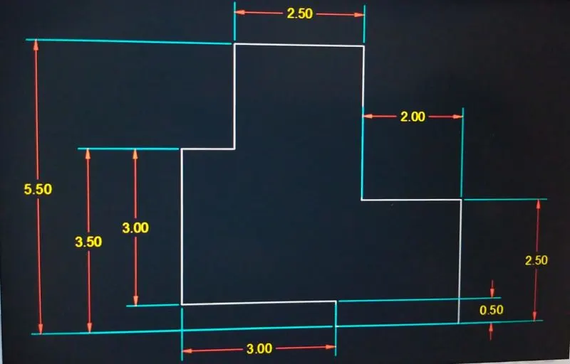
- AIM : CREATE THE FOLLOWING GEOMATRIC FIG BY USING AUTOAD SOFTWARE :
- PROCEDURE :
- first the open the software
- give the command QNEW and press the ENTERE key
- click on imperical templete
- select ADVANCE SETUP
- unit : Decimal , precision :0.00
- angle :decimal degree , precision :0
- angle measure : East
- angle direction : counterclockwise
- area : 20*20
- and finished , lets start
- ortho mode : ON
- object snap : ON select endpoint and midpoint
- command : PL ( for polyline )
- select starting point
- @0.50<90
- @3.00<180
- @3.00<90
- @1.00<0
- @2.00<90
- @2.50<0
- @3.00<270
- @2.00<0
- @2.50<270
- then join the endpoint of line (@0.50<90)
- press : ENTER
- command :DIM (for dimension )
- give the dimension to all points
- select all dimension
- go to the properties
- change the colour of arrow and text
- text colour :yellow
- arrow colour :red
- RESULTS :
- BELOW THE GEOMETRIC FIG IS GIVEN OF ABOVE PROCEDURE
- COMMAND USED :
- POLYLINE :PL
- DIMENSION :DIM
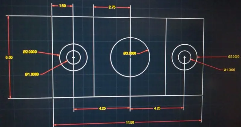
- AIM : DRAW THE GIVEN FIG IN AUTOCAD SOFTWARE BY USING TOOLS IN AUTOCAD :
- PROCEDURE :
- first the open the software
- give the command QNEW and press the ENTERE key
- click on imperical templete
- select ADVANCE SETUP
- unit : Decimal , precision :0.00
- angle :decimal degree , precision :0
- angle measure : East
- angle direction : counterclockwise
- area : 20*20
- and finished , lets start
- ortho mode : ON
- object snap : ON select endpoint and midpoint
- command : PL ( for polyline )
- select the starting point
- @11.50<0
- @6.00<90
- @11.50<180
- @6.00<270
- closed
- command :L (for line )
- select the first point of line (11.50<0)
- @1.50<0
- @3.00<90
- press : ENTER
- command :C (for circle )
- select the point of line (3.00<90)
- diameter :1.00
- press :ENTER
- again go for command :c (for circle )
- select the endpoint of line (@3.00<90)
- diameter :2.00
- press : ENTER
- delete line :@3.00<90
- press :ENTER
- command :l( for line)
- starting point : select the midpoint of circle (
- @4.25<0
- @3.00<90
- press :ENTER
- command :C (for circle )
- select the starting point of line (@3.00<90)
- click on DIAMETER
- dimater :3
- press : ENTER
- delete :@3.00<90
- command : L (FOR LINE )
- select the midpoint of circle having diameter is 3
- @4.25<0
- @3.00<90
- press :ENTER
- command :C (for circle )
- starting point :click on endpoint of line (@3.00<90)
- clinck on DIAMETER
- diameter :1
- press :ENTER
- Command :C (For circle )
- select last point of line @3.00<90
- click on diamter
- diamter :2
- press : ENTER
- delete line 1:@3.00<90
- command :L (For line )
- starting point :midpoint of circle having diamter 3
- @2.72<180
- @6.00<900
- press : enter
- again click on midpoint of circle having diameter 3
- @2.75<0
- @6.00<90
- press : ENTER
- Give the dimension and select it
- go to the properties
- text colour:Yellow
- arrow colour :red
- RESULTS :
- COMMAND USED :
- LINE :L
- CIRCLE :C
- ERRESE :E
- DIMENSION :DIM
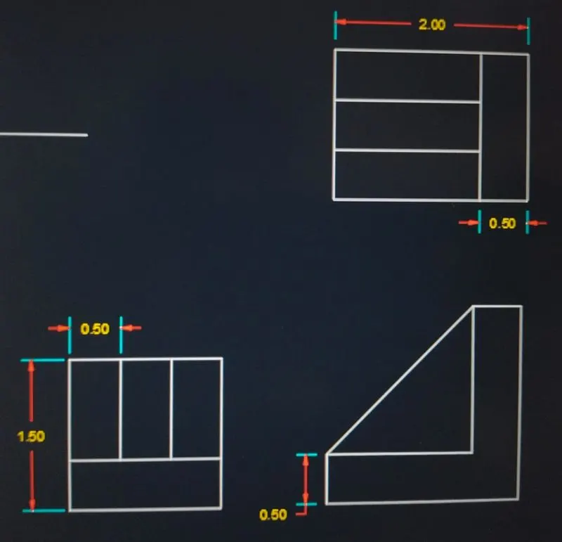
- AIM : CREATE THE FOLLOWING GEOMETRICS BY USING AUTOCAD SOFTWARE :
- PROCEDURE :
- first the open the software
- give the command QNEW and press the ENTERE key
- click on imperical templete
- select ADVANCE SETUP
- unit : Decimal , precision :0.00
- angle :decimal degree , precision :0
- angle measure : East
- angle direction : counterclockwise
- area : 20*20
- and finished , lets start
- Fig no :1
- command :L (for a line )
- select starting point
- ortho mode :ON
- object snap :ON select endpoint and midpoint
- @1.5<90
- @1.5<0
- @1.5<270
- closed
- command : O (ofset )
- give ofset distance 0.5
- select horizontal line object
- press :ENTER
- again go for ofset command
- and select the vertical line
- and give the 2 ofset line having each distance is 0.5
- fig no :2
- command :L (for line )
- select starting point
- @2.00<0
- @1.5<90
- @2.00<180
- @1.5<270
- press :ENTER
- command :o (for ofset)
- give the ofset distance 0.5
- select the object
- and give the one ofset
- press :ENTER
- command :o (ofset )
- give the offset distance is 0.5
- select the object
- and give the 2 offset line
- press :ENTER
- Fig no :3
- command : L (for line )
- select the startig point
- @2<0
- @2<90
- @0.5<180
- @1.5<270
- @1.5<180
- @0.5<270
- press :ENTER
- ortho mode : OFF
- command :L ( FOR LINE )
- select the endpoint of line (@0.5<270)
- and join the endpoint of line @(0.5<180) by using object snap mode
- press : ENTER
- give the dimension to all fig
- command :M (for move )
- move the fig in one line
- press :ENTER
- select dimension
- go to the properties
- change the colour of text and arrow
- RESULTS
- COMMAND USED
- LINE : L
- OFSET :O
- DIMENSION :DIM
- MOVE :M
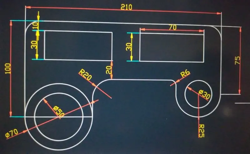
- AIM : DRAW THE FOLLOWING GEOMATRIC FIG USING AYTOCAD SOFTWARE :
- PROCEDURE :
- first the open the software
- give the command QNEW and press the ENTERE key
- click on imperical templete
- select ADVANCE SETUP
- unit : Decimal , precision :0.00
- angle :decimal degree , precision :0
- angle measure : East
- angle direction : counterclockwise
- area : 20*20
- and finished , lets start
- command :L (for line )
- select the starting point
- @100<90
- @210<0
- @75<270
- press :ENTER
- command :F (fillet )
- mode :triam
- radius :15
- click on line (@100<900)and (210<0)
- again same way
- command :F (fillet )
- Mode :triam
- radius :15
- select line (210<0) and (75<270)
- command :L (Line )
- starting point :endpoint of line (@100<90)
- @20<0
- @10<270
- @70<0
- @30<270
- @70<180
- @30<90
- press : ENTER
- delete line :(@10<270)
- command :L ( for line )
- starting point :endpoint of line (@210<0)
- @20<180
- @10<270
- @70<180
- @30<270
- @70<0
- @30<90
- press : ENTER
- delete line :@10<270
- command :L (for line )
- starting point :first point of line (@100<90)
- @70<0
- @40<90
- press : ENTER
- command : C (For circle )
- select circle ,radius option
- starting point :Midpoint of line (@70<0)
- radius :35
- press :ENTER
- again ,command :C (circle )
- select circle ,diameter mode
- diameter :50
- press :ENTER
- command : E (erase )
- delete line :@70<0
- command :L (for line )
- starting point :endpoint of line (@75<270)
- @50<180
- @15<90
- press : ENTER
- Command :C (for circle )
- start point :midpoint of line (@50<180)
- select circle ,radius mode
- radius :25
- press : ENTER
- command : C ( for circle )
- select circle ,diameter mode
- starting point :midpoint of line (@50<180)
- diameter :30
- press : ENTER
- DELETE LINE :@50<180
- then ,
- command :L (for line )
- join the line (@15<90) and (@40<90)
- press : ENTER
- command :F (for FILLETE)
- radius :6
- select line (@15<90) and another connected line
- again fillete opetion
- radius :20
- select line (@40<90) and another connected line
- press :ENTER
- RESULTS :
- command used :
- LINE :L
- CIRCLE :C
- EREASE :E
- FILLETE :F
- DIMENSION :DIM
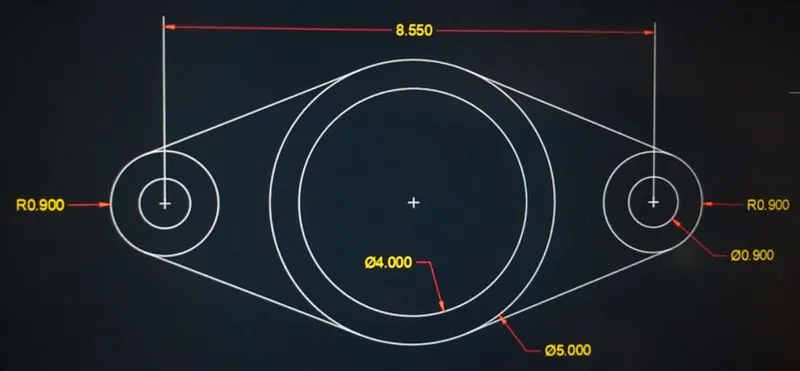
- AIM : CREATE THE GEOMETRIC FIG BY USING AUTOCAD SOFTWARE :
- PROCEDURE :
- first the open the software
- give the command QNEW and press the ENTERE key
- click on imperical templete
- select ADVANCE SETUP
- unit : Decimal , precision :0.00
- angle :decimal degree , precision :0
- angle measure : East
- angle direction : counterclockwise
- area : 20*20
- and finished , lets start
- object snap : ON endpoint ,midpoint and tangent
- command :L (for line )
- select the starting point
- @8.550<0
- press : ENTER
- command :C (for circle )
- select the circle,radius mode
- starting point :starting point of line (@8.550<0)
- radius :0.90
- press : ENTER
- command :C (for circle )
- select the circle , diameter mode
- diameter :0.90
- press : ENTER
- Command :c (for circle )
- starting point :endpoint of line (@8.50<0)
- select circle radius mode
- radius :0.90
- press : ENTER
- command : c (for circle )
- select circle ,diameter mode
- starting point : endpoint of line (@8.500<0)
- diameter :0.90
- then :
- delete line: @8.850<0
- command :L (for line )
- join the tangent to the outer circle
- RESULTS :
- COMMAND USED :
- LINE :L
- CIRCLE :C
- ERASE : E
- DIMENSION :DIM
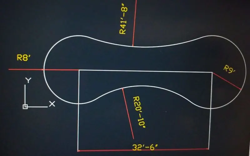
- AIM: DRAW THE GEOMATRIC FIG BY USING AUTOCAD SOFTWARE :
- PROCEDURE
- first the open the software
- give the command QNEW and press the ENTERE key
- click on imperical templete
- select ADVANCE SETUP
- unit : Engineering , precision :0.0
- angle :decimal degree , precision :0
- angle measure : East
- angle direction : counterclockwise
- area : 20*20
- and finished , lets start
- command:L (for line )
- @32'-6" <0
- press : ENTER
- command :C (for circle )
- select the first point of line (@32'-6"<0)
- select circle, radius mode
- radius :8'
- press : ENTER
- Command :c(for circle )
- select the endpoint of line (@32'-6"<0)
- select the circle ,radiuds mode
- radius :9'
- press enter
- command :c ( for circle )
- select the tan tan radius mode
- click on circle having radius is 8' and 9'
- and radius is 20'-10"
- press : ENTER
- Tream the unrequired part
- again
- command :c (for circle )
- move the curcor upward direction
- select the tan tan mode
- click on both two circle
- and radius is 41'-8"
- press : ENTER
- Trim unrequired part
- give the dimension
- RESULTS :
- COMMAND USED :
- LINE :L
- CIRCLE :C
- TRIM :TR
- DIMENSION :DIM
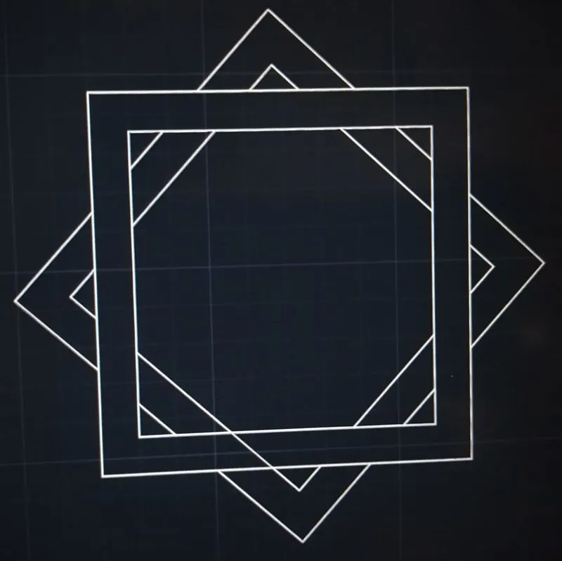
- AIM : DRAW THE GEOMETRIC FIG BY USING THE AUTOCAD SOFTWARE :
- PROCEDURE :
- first the open the software
- give the command QNEW and press the ENTERE key
- click on imperical templete
- select ADVANCE SETUP
- unit : Engineering , precision :0.0
- angle :decimal degree , precision :0
- angle measure : East
- angle direction : counterclockwise
- area : 20*20
- and finished , lets start
- command :REC (rectangle)
- select the starting point
- click on DIMENSION
- length: 5
- width :5
- press :ENTER
- Command :o (ofset )
- give the ofset distance 0.5
- select the object
- press :ENTER
- command: MIR (mirror)
- select the object
- and rotate it
- press : ENTER
- command :TR (triem)
- RESULTS :
- COMMAND USED:
- RECTANGLE: REC
- TRIEM:TR
- OFSET : O
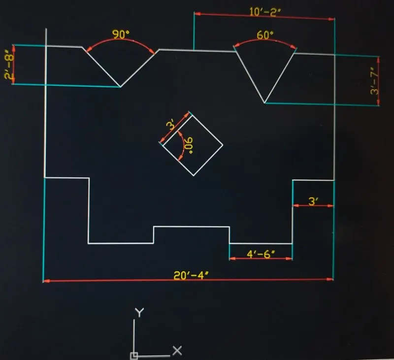
- AIM : CREATE THE FOLLOWING FIG BY USING VARIOUS TOOLS IN AUTOCAD SOFTWARE :
- PROCEDURE :
- first the open the software
- give the command QNEW and press the ENTERE key
- click on imperical templete
- select ADVANCE SETUP
- unit : Engineering , precision :0'-0"
- angle :decimal degree , precision :0
- angle measure : East
- angle direction : counterclockwise
- area : 20*20
- and finished , lets start
- command :L (For line )
- @9'<270
- @3'<0
- @4'-6"<270
- @4'-6"<0
- @1'-2"<90
- @5'-4"<0
- @1'-2"<270
- @4'-6"<0
- @4'-6"<90
- @3'<0
- @9'<90
- @10'-2"<180
- press :ENTER
- command :L (FOR LINE )
- start point : midpoint of line (@10'-2"<180)
- @3'-7"<270
- press : ENTER
- polar tracking :ON
- select the mode 30,60,90,120
- commad :L (for line )
- select the endpoint of line (@3'-7"<270)
- mark the v having angle is 60 degree
- delete the line (@3'-7"<270)
- triam the midline of v portion
- press : enter
- command :L ( for line )
- select the endpoint of line (@10'-2"<180)
- @10'-2"<180
- press : ENTER
- command :l(for line )
- select the mid point of line (10'-2"<180)
- @2'-8"<270
- press :ENTER
- command :L (for line )
- go for v portion
- polar tracking :ON
- select the mode 45,90,135,180
- draw the v portion at angle og 90 degree
- trim the midline of v portion
- command :L (for line )
- select the midpoint of line 20'-4" from upper face
- @6'-9"<270
- press : enter
- command :REC ( for rectangle )
- starting point : select the endpoint of line (@6'-9"<270)
- click on DIMENSION
- Length:3'
- width :3'
- then rotate it at an angle of 90 degree
- press :ENTER
- delete line :(@6'-9"<270)
- give the dimension to all point
- go the properties
- change colour of text and arrow
- text colour : YELLOW
- arrow colour : RED
- press :ENTER
- RESULTS
- COMMAND USED:
- LINE :L
- RECTANGLE :REC
- TRIM :TR
- DIMENSION :DIM