Creating a Floor plan, Footing detail and Isometric view using AutoCad
- CRATE A FLOOR PLAN , FOOTING DETAILS AND ISOMETRIC VIEW USING AUTOCAD :
- SOFTWARE USED : AUTODESK AUTOCAD 2021
- AIM : DEAW THE CROSS SECTION OF A LOAD BEARING WALL OVER THE SPREAD FOOTING . USE THE AUTO CAD
- SOFTWARE TO DRAW THE C.S FOOTING :
- PROCEDURE :
- first the open the software
- give the command QNEW and press the ENTERE key
- click on imperical templete
- select ADVANCE SETUP
- unit : decimal , precision :0.00
- angle :decimal degree , precision :0.00
- angle measure : East
- angle direction : closkwise
- area : 20*20
- and finished , lets start
- give the ds command for some seeting
- snap spacing : x and y spacing =0.5
- grid spacing :x and y spacing =0.5
- press ok key
- give command REC for rectangle
- starting point is 1,1
- press DIMENSITION
- length :0.90
- width :0.25
- command REC
- starting point :1.2,1.25
- click on DIMENSITON
- length :0.50
- width :0.40
- give command REC
- starting point :1.25,1.65
- select DIMENSITION
- length :0.40
- width:0.40
- press ENTER key
- command :REC
- starting point :1.30,2.05
- click on DIMENSITION
- length :0.30
- width:0.60
- command :REC
- starting point :1.30,2.65
- select DIMENSITION option
- length :0.30
- width:0.05
- command :REC
- starting point :1.30,2.7
- select DIMENSITION option
- length:0.30
- width :1.0
- command :L for line
- starting point :1.25,2.05
- @0.15<270
- @1.15<180
- @0.15<90
- @1.15<0
- then closed
- command :L for line
- starting point : 0.40,2.05
- @0.15<90
- @0.30<0
- @0.15<90
- @0.30<0
- @0.15<90
- @0.30<0
- then closed
- RESULTS :
- cross section of load bearing wall over spread footing is given below :
-
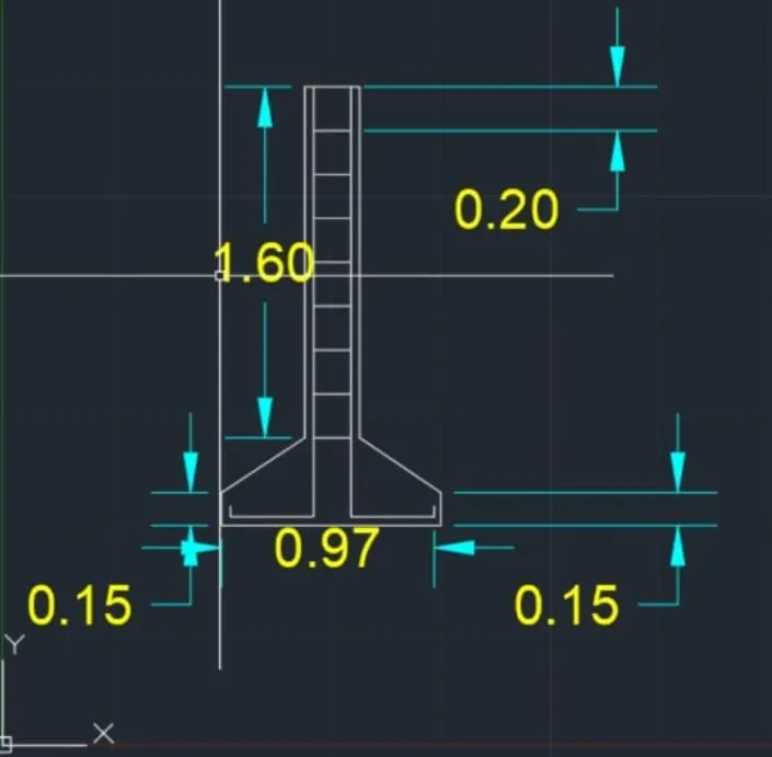
AIM : TO DRAW THE CROSS SECTION OF ISOLATED FOOTING :
-
PROCEDURE :
give the command QNEW and press the ENTERE key
click on imperical templete
select ADVANCE SETUP
unit : decimal , precision :0.00
angle :decimal degree , precision :0.00
angle measure : East
angle direction : closkwise
area : 20*20
and finished , lets start
give the ds command for some seeting
snap spacing : x and y spacing =0.5
grid spacing :x and y spacing =0.5
press ok key
command :L for line
starting point :1,1
@1<0
@0.15<90
press ENTER
command : L for line
starting point :1,1
@0.15<90
enter
command: line
starting point :1.04,1.04
@0.38<0
@1.96<90
@0.17<0
@1.96<270
@0.38<0
command : line
starting point :1.04,1.04
@0.05<90
press : ENTER
command : for line
starting point :1.42,3.00
@0.04<180
@1.60<270
then joint the cordinate (1.38,1.40) and (1,1.15) using line tool
then , command :L
starting point :1.59,3.00
@0.04<0
@1.60<270
similarly above process join the coordinate
then command :O for offset
give
offset distence 0.20
press offset line and then select MULTIPLE option and give the offset
press ENTER -
RESULTS :
-
CEOSS SECTION OF A ISOLATED FOOTING GIVEN BELOW :
-
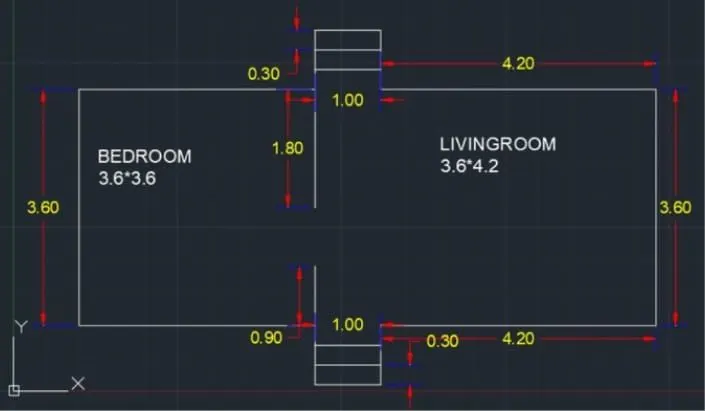
AIM :DRAW A LINE DIAGRAM OF A TWO BEDROOM BUILDING :
-
PROCEDURE :
give the command QNEW and press the ENTERE key
click on imperical templete
select ADVANCE SETUP
unit : decimal , precision :0.00
angle :decimal degree , precision :0.00
angle measure : East
angle direction : closkwise
area : 20*20
and finished , lets start
give the command QNEW and press the ENTERE key
click on imperical templete
select ADVANCE SETUP
unit : decimal , precision :0.00
angle :decimal degree , precision :0.00
angle measure : East
angle direction : closkwise
area : 20*20
and finished , lets start
L for line
starting point :1,1
@3.60<0
press :ENTER
command :L
starting point : 1,1
@3.60<90
@3.60<0
@0.9<90
@1<0
@0.9<270
@4.20<0
@3.60<270
@4.20<180
@0.9<270
@1<180
@0.9<90
closed
command :L
starting point : 4.60,1
@0.9<90
press :ENTER
command :L
starting point :4.60,4.60
@1.80<270
closed
command :O for offset
give the offset distence 0.30
select offset line and option MULTIPLE
give the officet and dimensition and finished it -
RESULTS :
-
LINE DIAGRAM OF TWO BEDROOM IS GIVEN BELOW :
-
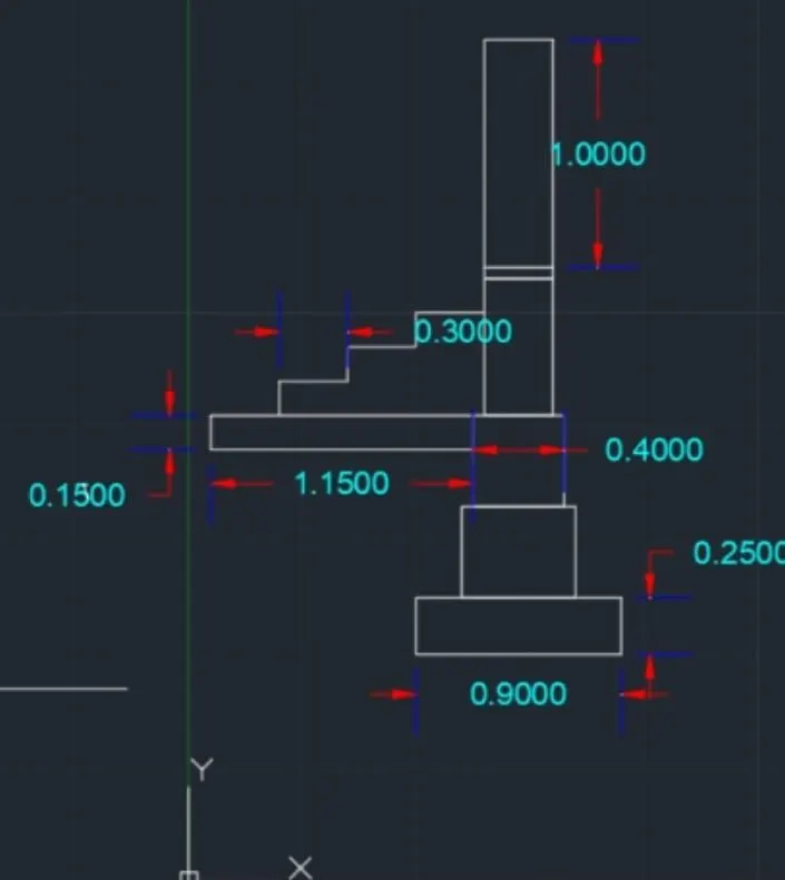
DRAW THE CROSS SECTION OF A LOAD BEARING WALL WHICH SHOWS THE FOUNDATION DETAILS :
-
PROCEDURE :
give the command QNEW and press the ENTERE key
click on imperical templete
select ADVANCE SETUP
unit : decimal , precision :0.00
angle :decimal degree , precision :0.00
angle measure : East
angle direction : closkwise
area : 20*20
and finished , lets start
give the command QNEW and press the ENTERE key
click on imperical templete
select ADVANCE SETUP
unit : decimal , precision :0.00
angle :decimal degree , precision :0.00
angle measure : East
angle direction : closkwise
area : 20*20
and finished , lets start
command :REC for rectangle
starting point :1,1
press DIMENSITION
length :0.90
width :0.45
press ENTER
command :REC for rectangle
starting point :1.15,1.45
click on DIMENSITION
length:0.60
width :0.40
press ENTER
command :REC
Starting point :1.20,1.85
press DIMENSITION
length:0.50
width :0.30
press ENTER
Command :REC
starting point :1.25,2.15
click on DIMENSITION
length :0.40
width:0.60
command :REC
starting point :1.30,2.75
click on DIMENSITION
length :0.30
width:1.00 -
RESULTS :
-
CROSS SECTION OF THE LOAD BEARING WALL SHOWING THE FOUNDATION DETAILS IS GIVEN BELOW :
sn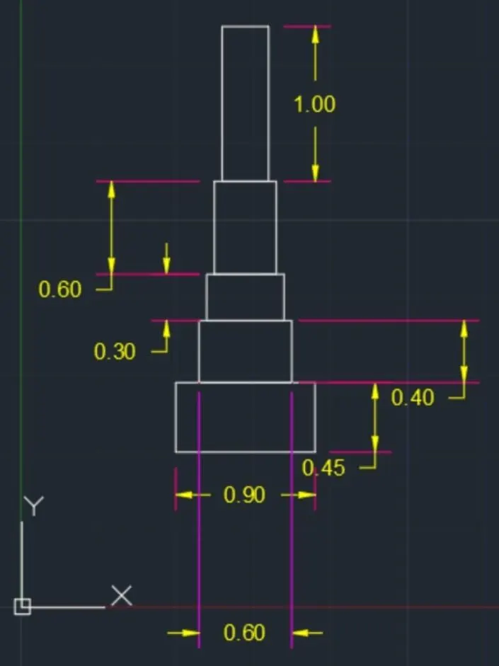
-
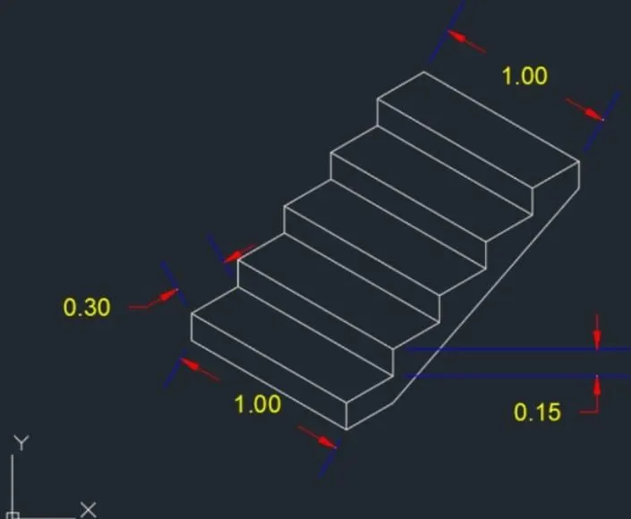
AIM :DEAW THE ISOMATRIC VIEW OF A STEPS :
-
PROCEDURE :
Open the AUTOCAD SOFTWARE
give the command QNEW
press on imperical templets
advance setup decimal
angle : decimal degree precision :0.00
and finished it
give the command ds
in drafting seating ,
snap mode :off
grid mode off
isomatric snap: ON
Ortho mode :ON
Command :L for line
starting point :1,1
give the distence 1 and isoplane facing left
then give the distance 0.15
after that give the distance 0.30
use isoplane fasing left ,right and top view
this process is done till steps are formed -
RESULTS :
-
ISOTROPIC VIEW OF A STEPS given below :
-
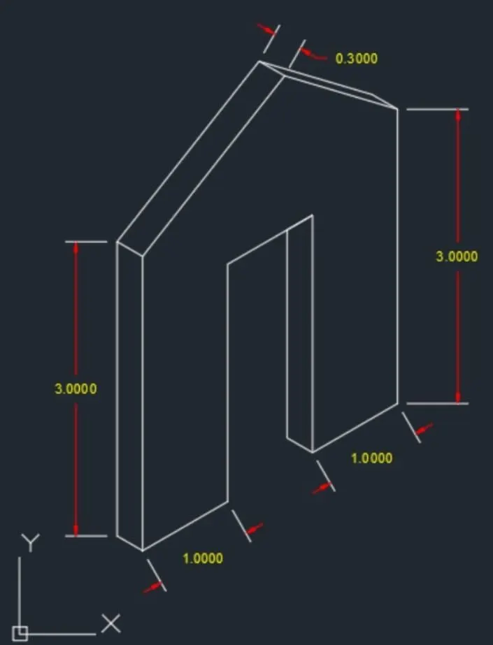
AIM :DRAW THE ISOTROPHIC VIEW OF A GABLE WALL :
-
PROCEDURE :
Open the AUTOCAD SOFTWARE
give the command QNEW
press on imperical templets
advance setup decimal
angle : decimal degree precision :0.00
and finished it
give the command ds
in drafting seating ,
snap mode :off
grid mode off
isomatric snap: ON
Ortho mode :ON
give the line command
select the starting point 1,1
give the distence 3
use isoplane top view
give the distance 0.30 and draw
then distance 1 and drow the door -
by giving peoper distance and use og isoplane top views, right views and left view complete the diagram
-
RESULTS :
-
ISOMATRIC VIEW OF GABLE WALL IS GIVEN BELOW :