Project 1 _Creating an Architectural plan for the provided plot size and develop relevant basic structural drawings
Design and Draft a layout of a residential building with the following details:
a. Plot Size: 60’x20’(18.3m x6m)
b. Orientation- Facing East
c. Develop the following: 1. Architectural Drawing (Floor Plan, Elevations, and Sections) 2. Structural Drawing (Column, Bean, Footing Plan)
DEVELOPING ARCHITECTURAL AND STRUCTURAL DRAWINGS OF A RESIDENTIAL BUILDING
AIM: To draw,
- Architectural Drawings of Floor Plan, Elevations, and Sections
- Structural Drawings of Column, Beam and Footing Plan.
INTRODUCTION:
- Architectural and structural drawings are generally considered to be the drawings of steel, wood, concrete,and other materials used to construct buildings, ships, planes, bridges, towers, tanks, and so on.
- A structural drawing, a type of engineering drawing, is a plan or set of plans and details for how a building or other structure will be built.
- Structural drawings are generally prepared by registered professional engineers, and based on information provided by architectural drawings.
- The structural drawings are primarily concerned with the load-carrying members of a structure.
- They outline the size and types of materials to be used, as well as the general demands for connections.
- Architectural drawings are used by architects and others for a number of purposes to develop a design idea into a coherent proposal, to communicate ideas and concepts, to convince clients of the merits of a design, to assist a building contractor to construct it based on design intent, as a record of the design and planned development, or to make a record of a building that already exists.
COMMANDS USED:
- Limits command
- Line command
- Offset command
- Hatch command
- Dimlinear command
- Dimstyle command
- Units command
- Extend command
- Fillet command
- Trim command
- Join command
- Circle command
- Line weight command
- Line type command
- Object snap command
PROCEDURE:
1. Architectural Drawings of Floor Plan, Elevations, and Sections:
Step:-1
Ground floor plan:
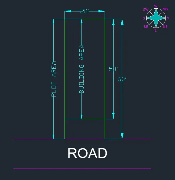
- First we have to draw the plot area and building area using the line command and dimlinear command as shown in the below figure.
- Next we have to draw the line hrozontally forward with the length of 20'.
- And next again draw the line upwards from the previous line with the length of 50'.
- From the top from previous line again we draw the line backwards with the length of 18'-4"
- Next from previous line we draw the line downwards with the length of 39'-9".
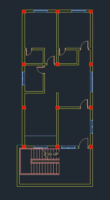
- Now from the left side corner of the 1st line we draw the another line from thet edge with the length of 10'-1".
- Next join the to edges with the small horizontal line to join them, as shown in the below figure.
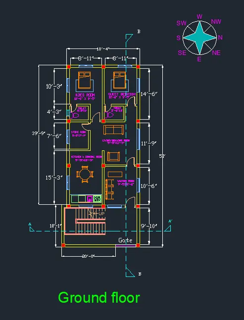
- Now we draw the master bedroom with the size of 10'-6" x 9'-5".
- Next we draw the attached toilet with the size of 5'-5" x 4'-0".
- Next we draw the Guest bed room with the size of 10'-6" x 9'-5".
- Next we draw the attached toilet with the size of 5'-6" x 4'-0".
- Next we draw the store room with the size of 5'-5" x 7''-9".
- Next we draw the Living/ drawing room with the size of 9'-5" x 11'-9" using the line command and trim command.
- Next we draw the kitchen room and dinning room with size of 9'-5" x 15'-3".
- Next we draw the waiting room with the size of 9'-5" x 10'-6".
- Next we draw the staircase with the tread of 9 inches and riser of 6 inches, and we also draw the entrance gate facing east.
- Next we draw the all doors with the size of 800 x 2000mm except toilet doors.
- Next we draw the toilet doors with the size of 700 x 2100mm.
- Next we draw the all windows with the size of 900 x 1200mm.
- Then after we use the dimlinear command to put the dimensions to the rooms.
- Next we draw the furniture things where they are required.
- Now we select the Single text command to indicate the rooms.
- Next we draw the direction symbol using the circle command, line command and text command as shown in the below figure.
- Finally, we indicate the total drawing using the Single text command as Ground floor plan as shown in the figure.
Step:2
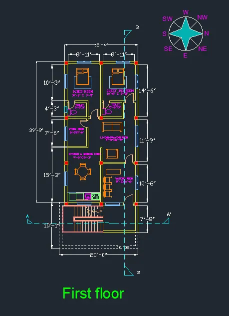
First floor plan:
- Next we have to draw the line hrozontally forward with the length of 20'.
- And next again draw the line upwards from the previous line with the length of 50'.
- From the top from previous line again we draw the line backwards with the length of 18'-4"
- Next from previous line we draw the line downwards with the length of 39'-9".
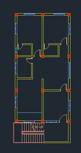
- Now from the left side corner of the 1st line we draw the another line from thet edge with the length of 10'-1".
- Next join the to edges with the small horizontal line to join them, as shown in the below figure.
- Now we draw the master bedroom with the size of 10'-6" x 9'-5".
- Next we draw the attached toilet with the size of 5'-5" x 4'-0".
- Next we draw the Guest bed room with the size of 10'-6" x 9'-5".
- Next we draw the attached toilet with the size of 5'-6" x 4'-0".
- Next we draw the store room with the size of 5'-5" x 7''-9".
- Next we draw the Living/ drawing room with the size of 9'-5" x 11'-9" using the line command and trim command.
- Next we draw the kitchen room and dinning room with size of 9'-5" x 15'-3".
- Next we draw the waiting room with the size of 9'-5" x 10'-6".
- Next we draw the staircase with the tread of 9 inches and riser of 6 inches, and we also draw the entrance gate facing east.
- Next we draw the all doors with the size of 800 x 2000mm except toilet doors.
- Next we draw the toilet doors with the size of 700 x 2100mm.
- Next we draw the all windows with the size of 900 x 1200mm.
- Then after we use the dimlinear command to put the dimensions to the rooms.
- Next we draw the furniture things where they are required.
- Now we select the Single text command to indicate the rooms.
- Next we draw the direction symbol using the circle command, line command and text command as shown in the below figure.
- Finally, we indicate the total drawing using the Single text command as Ground floor plan as shown in the figure.
Step:-3
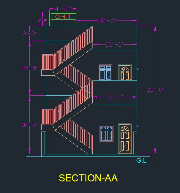
Section-AA
- First of all we have to draw the line with the length of 20' horizontally.
- Next draw a line from previous line with the length of 23'-0" vertically upwards.
- From the precious line we draw the line backwards with the length of 20' horizontally.
- Next join the first line and the last line with the length of 23'-0".
- Next we draw the staircase using the line command with the 9 inches tread and 6 inches riser.
- And also draw the railing to the stairs to look good in the front view.
- Next draw the doors and windows in the ground floor and first floor as shown in the below figure.
- And draw the water tank on the top at left side of the building.
- Finally we put the dimensions where ever they required using the dimlinear command.
- And write the elevation name downside of the drawing using the single text command.
Step:-4
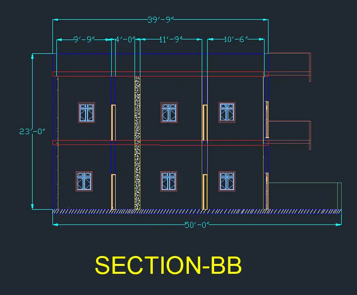
Section-BB
- First we have to draw the line with the length of 50'-0" using the line command.
- And then offset that line with the length of 150mm offset.
- Next draw the vertical line fron the left side corner of the first line with the length of 23'-0".
- Next draw the floors using the line command and offset command.
- Next draw the doors and windows with the help of line command and trim command.
- The thickness of slabs are 200mm for both floor slabs.
- And draw the water tank on the top at left side of the building.
- Finally we put the dimensions where ever they required using the dimlinear command.
- And write the elevation name downside of the drawing using the single text command.
Step:-5
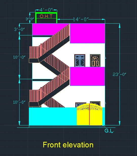
Front Elevation:
- First of all we have to draw the line with the length of 20' horizontally.
- Next draw a line from previous line with the length of 23'-0" vertically upwards.
- From the precious line we draw the line backwards with the length of 20' horizontally.
- Next join the first line and the last line with the length of 23'-0".
- Next we draw the staircase using the line command with the 9 inches tread and 6 inches riser.
- And also draw the railing to the stairs to look good in the front view.
- Next draw the doors and windows in the ground floor and first floor as shown in the below figure.
- And draw the water tank on the top at left side of the building.
- After that we draw the compound wall and draw the gate attached to the compound wall.
- Finally we put the dimensions where ever they required using the dimlinear command.
- And write the elevation name downside of the drawing using the single text command.
- Next we use the hatch command to hatch the different parts in building with different colours.
- Next use single text command to indicate the ground level of the building as shown in the below figure.
Step:-6
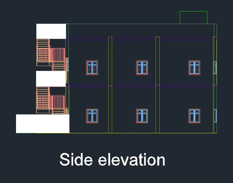
Side elevation:
- First we have to draw the line with the length of 50'-0" using the line command.
- And then offset that line with the length of 150mm offset.
- Next draw the vertical line fron the left side corner of the first line with the length of 23'-0".
- Next draw the floors using the line command and offset command.
- Next draw the doors and windows with the help of line command and trim command.
- The thickness of slabs are 200mm for both floor slabs.
- And draw the water tank on the top at left side of the building, and we draw the staircase in the side elevation.
- As we designed a building, when we see the building in side view that will be look like the figure shown below.
2. Structural Drawings of Column, Beam and Footing Plan:
Step:-1
Column Layout:
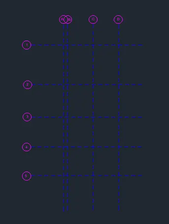
- First we have to draw the grid lines as shown in the below figure.
- Next indicate the vertcal lines with the alphabates.
- And next indicate the horizontal lines with the numbers, as shown in the figure below.
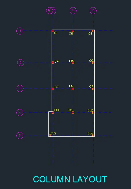
- Next draw the columns where ever they are required in the figure.
- Next use the single text command to indicate the columns with C1, C2, C3, C4, C5, C6, C7, C8, C9, C10, C11, C12, C13, C14.
- Next use the single text command and write the text as 'Column Layout' downwards to the figure.
Step:-2
Beam Layout:
- First we have to draw the grid lines as shown in the below figure.
- Next indicate the vertcal lines with the alphabates.
- And next indicate the horizontal lines with the numbers, as shown in the figure below.
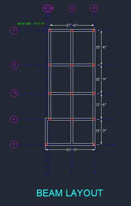
- Next draw the columns where ever they are required in the figure.
- Next we have to draw the beams using the line command with reference to the columns.
- Next put the dimensions where ever they required using the dimlinear command, and the beam size is taken as 10" x 10".
- Next use the single text command and write the text as 'Beam Layout' downwards to the figure.
Step:-3
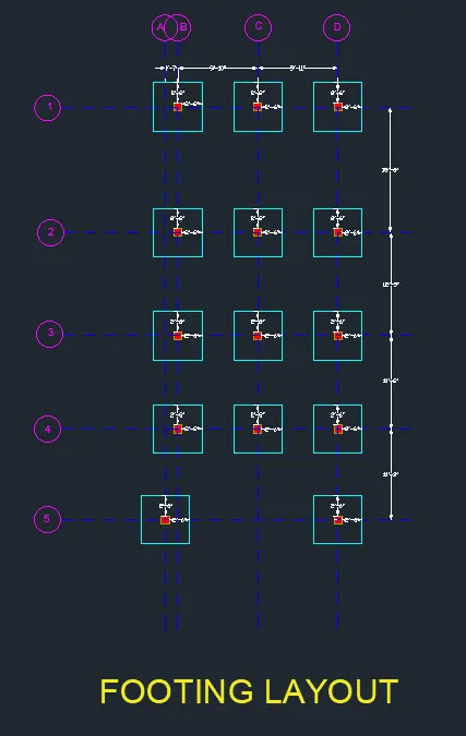
Footing Layout:
- First we have to draw the grid lines as shown in the below figure.
- Next indicate the vertcal lines with the alphabates.
- And next indicate the horizontal lines with the numbers, as shown in the figure below.
- Next we have to draw the column and footing with the required dimensions.
- We take the column size as 10" x 10".
- Next we do the offset of 2'-6" horizontally and vertically from the columns to form the footings.
- Then we drawn the footing layout with required dimensions.
- Finally we put the dimensions in the every part of the drawing using the dimlinear command.
- Next use the single text command and write the text as 'Footing Layout' downwards to the figure.
RESULT:-
- The architectural drawings(Floor Plan, Elevations, and Sections) and Structural drawings(Column, Beam and Footing Plan) are drawn successfully in the autocad in detailed manner.