Project 1 _Creating an Architectural plan for the provided plot size and develop relevant basic structural drawings
1.
AIM:-
Design and Draft a layout of a residential building with the following details:
a. Plot Size: 60’x20’(18.3m x6m)
b. Orientation- Facing East
c. Develop the following: 1. Architectural Drawing (Floor Plan, Elevations, and Sections)
2. Structural Drawing (Column, Bean, Footing Plan)
INTRODUCTION:-
Auto Cad is a commercial computer aided design (CAD) and drafting software,which was developed by Autodesk.
Auto cad was first released in December 1982 as a desktop running on mirocomputers with internal graphics controllers.
Auto cad is mainly used by industry,graphic designers,city planners,and other professionals.
COMMANDS USED:-
line,rectangle,offset,trim,dimension,layers,block,insert,extend,hatch
PROCEDURE:-
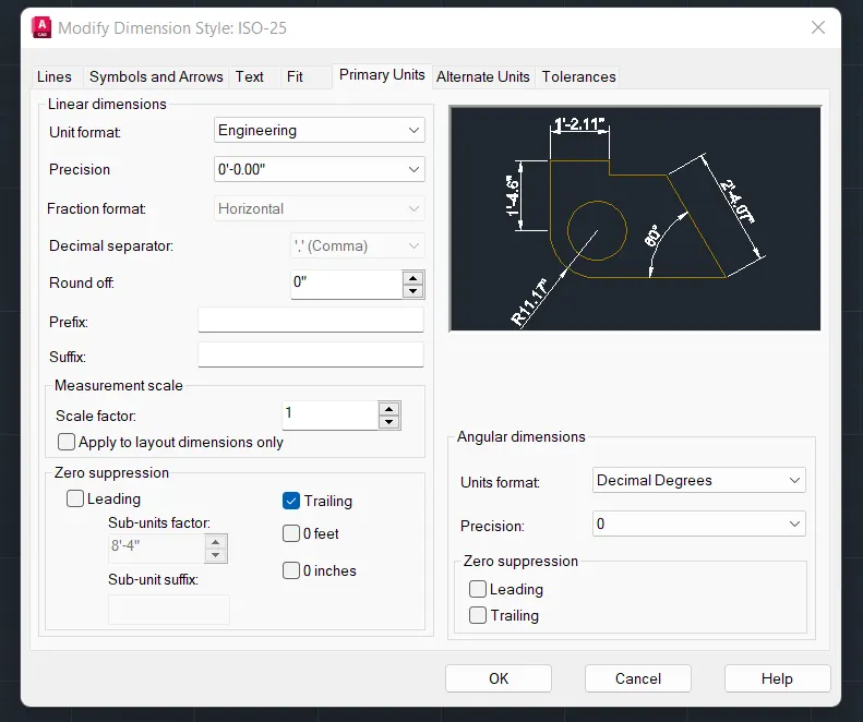
1.Firstly we have to change the unit system and decimal system to feet and inches, as we are going to make our plan according to feet and inches.
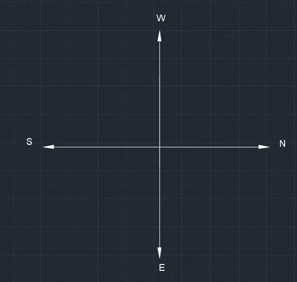
2. we will provide a direction of N,S,E,W that will help us in making or plan more accurately.
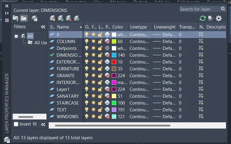
3.Then, we have to add all the layers that will be used in making the plan. providing different colours to the different layers helps in the visiblity of the layers and also if we want to work on a specific layer then this can also be done.
4.After providing the layers we have to draw the plan:-
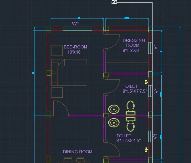
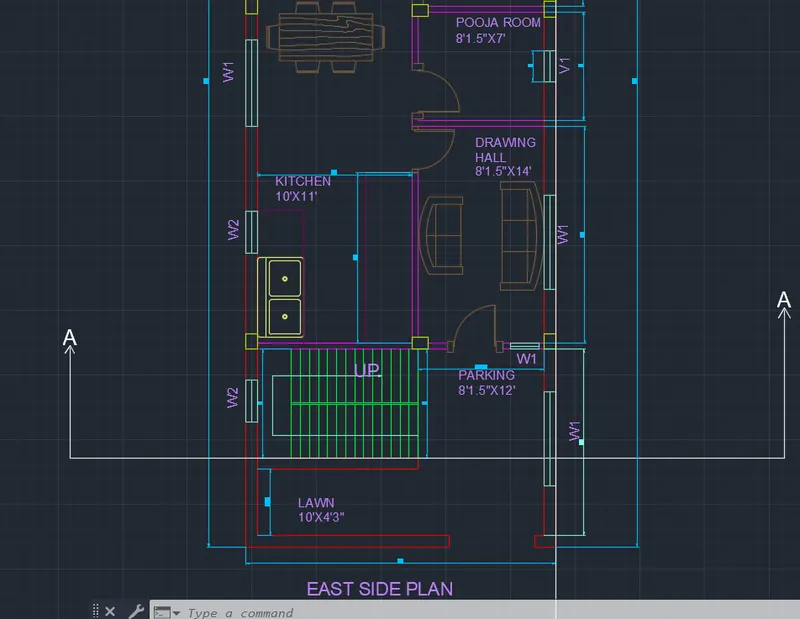
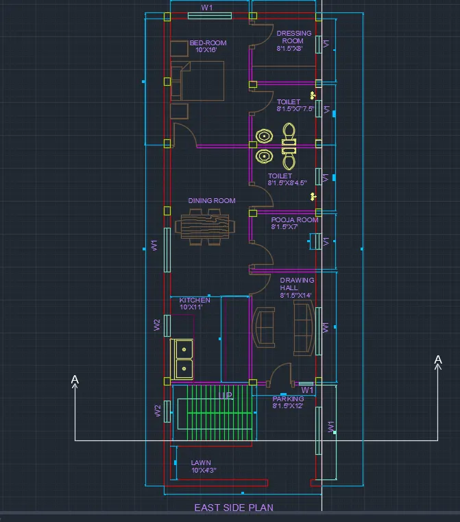
TOP VIEW PLAN
a. Make an outer boundary of 20'x60'
b. take an off set of 9" for the exterior wall
c.then by changing the layer start creating the interior walls (4.5')of the plan.
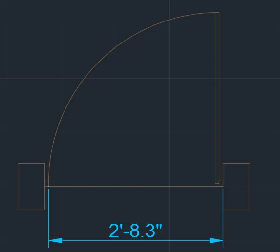
d.After that create the doors of the rooms.
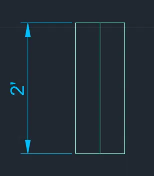
e. draw all the windows and the ventilators available in the room,toilet,pooja room,drawing room,kitchen
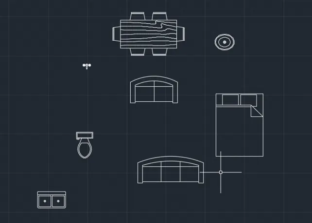
f. After that add all the furniture and sanatarty items to the plan and place them according to need.
g. Add dimensions to the drawing where ever needed.
result:-
EAST SIDE FRONT SECTION:-
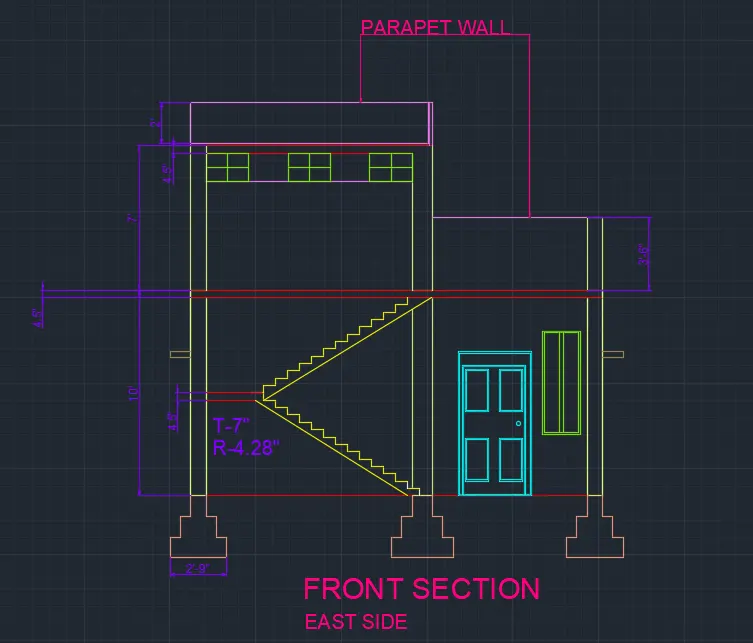
a. take the projection lines from the our top view plan.
b. then provide the column in the elevation as per top view plan.
c. provide the stairs in which the thread is of 7" and the height of the riser is 4.28".
d. privide the door in the front elevation i.e. of 7 feet from the ground level.
e. then provide the window at 3' above from the ground level.
f. provide a slab of 4.5" in the plan.
g. above the ground floor provide the parapet wall and the stair roof.
result:-
SIDE ELEVATION:-
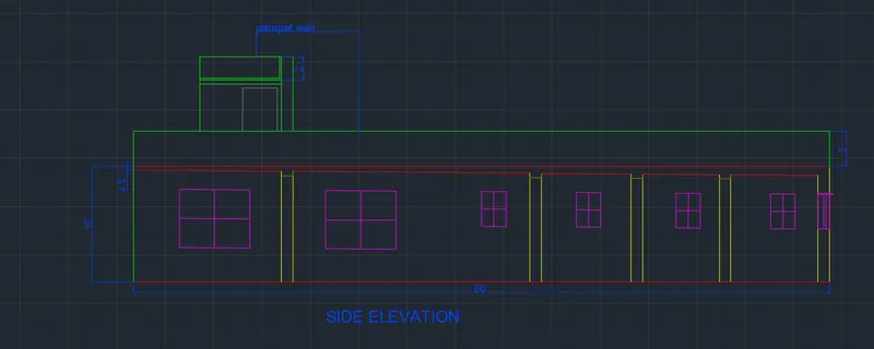
a.for the side elevation we have to create a wall of 60'x10'(widthx height).
b. provide the column in the side elevation by the help of projection line from the top view plan.
c.Provide all the windows and the ventilators in the plan.
d.above the slab of the the parapet wall is also made of height 3'.
e.also the stair roof is made having a height of 7'.
f.above stair roof create a parapet wall of 2'.
STRUCTURAL PLAN:-
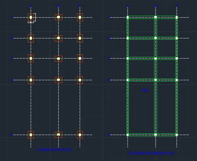
a. For structural plan we need to create 2 plan one for column and beam and other showing the foundation.
b. Create the column where ever provided in the plan, we can take the projection lines to provide a proper symmetry of the lines. The size of the column provided is 9"x12".
c. create the grid lines by changing the line type to dot dash. it should be provided centre to centre of the column and foundation.
d.simillarly create the beams of the structure in the structural plan.
result:-