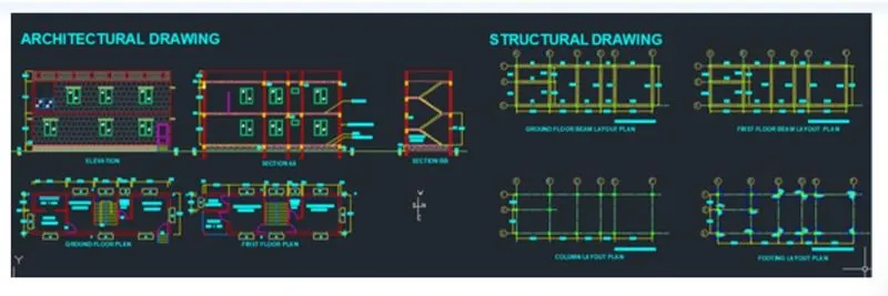
Project 1 _Creating an Architectural plan for the provided plot size and develop relevant basic structural drawings
- Project: Creating a Architectural plan for the provided plot size and develope relevant basic structural drawings
- Aim: To draw the Residential Building in the plot size of 60'x 20' (18.3m X 6m) facing East direction with the following drawings:
- Architectural Drawing :
- Site Plan
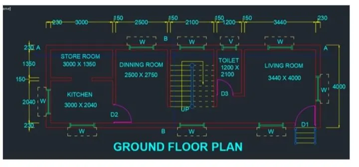
- Ground Floor Plan
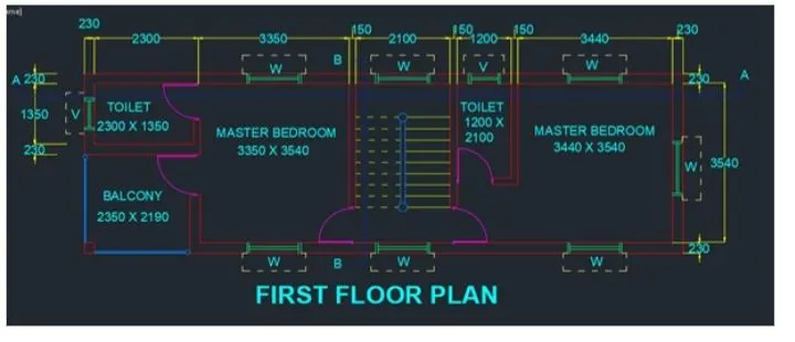
- First Floor Plan
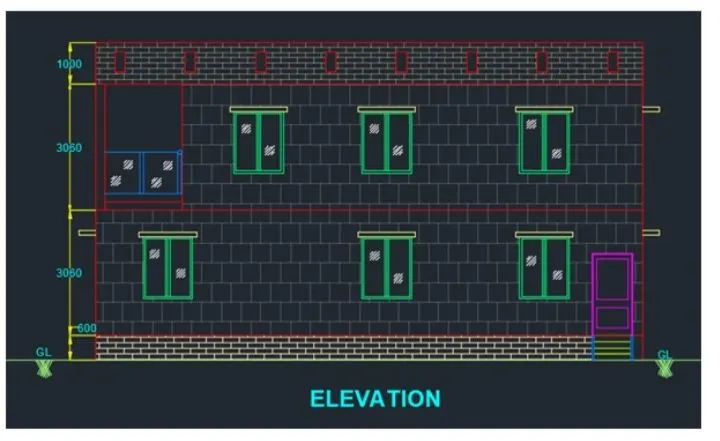
- Elevation
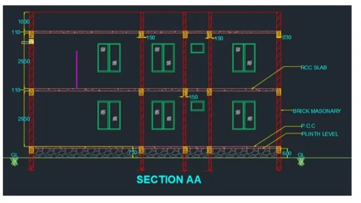
- Section
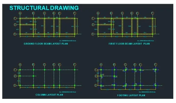
- Structural Drawing
- Column Layout Plan
- Beam Layout Plan
- Footing Layout Plan
- Introduction :-
- The general commands used for drawing the building is as follows :
- Line
- Polygon
- Rectangle
- Circle
- Erase
- Copy
- Trim
- Mirror
- Offset
- Extend
- Array
- Move
- Rotate
- Dimension
- Text
- Fillet
Etc.
- The dimensions:
- For external wall – 230mm
- For internal wall – 150 mm
- For Staircase : - Treads : 250 mm, Rise : 170mm
- The assumed dimensions :
For Windows:
- W – 1000 X 1500
- V – 700 X 500
For Doors:
- D1 – 1000 X 2000
- D2 – 900 X 2000
- D3 – 800 X 2000
- Procedure :-
- Click on AutoCAD application and open this application
- Type QNEW in command bar and enter
- Select default setting as Metric
- In default setting click on use a wizard and in that advance setting and set unit as decimal and precision as 0 and press Next
- Set Angle as Decimal Degree and precision as 0 and click next
- Set Angle Measure as EAST and press NEXT
- Set Angle Direction as Counter-Clockwise and press NEXT
- Set Area by providing Length as 50 and Width as 50
- Press finish
- Keep ortho, Object snap >ON
- Keep Snap and Grid > Off
- Un+enter
- Type > Decimal, Precision > 0
- Units to scale inserted content > milimeter
- Enter
- Site Layout :
- Take line command
- Specify first point anywhere
- Specify next point as - @18300>0
- Specify next point as - @6000>90
- Specify next point as - @18300>180
- Specify next point as - @6000>270
- Enter
- Take offset command
- Specify offset distance > 1000
- Select the object > click on both horizontal lines keeping curser towards inwords
- Enter
- Take offset command
- Specify offset distance > 2000
- Select the object > click on both horizontal lines keeping curser towards inwords
- Enter
- Take offset command
- Specify distance > 3000
- Select the object > Click on vertical right side line keeping curser inwords
- Specify offset distance > 5000
- Select the object > Click on vertical right side line keeping curser outwords to show the road
- Enter
- Stretch the vertical right side lines as shown below
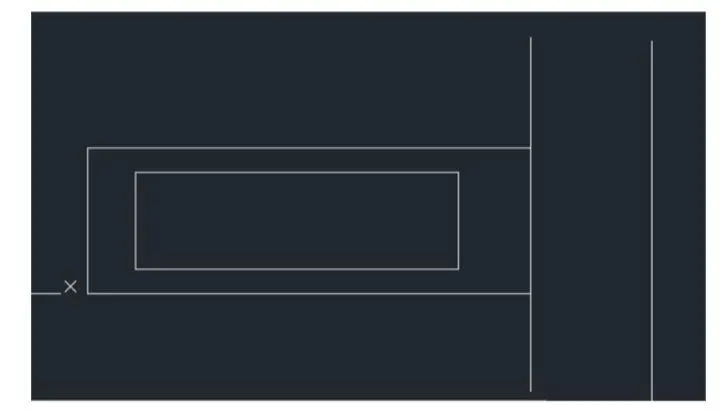
- Take hatch command
- Click on dropdown
- Select hatch style as ANSI32
- Click inside the rectangle to show the proposed building area r the area on which the building is going to built
- It will show you following results
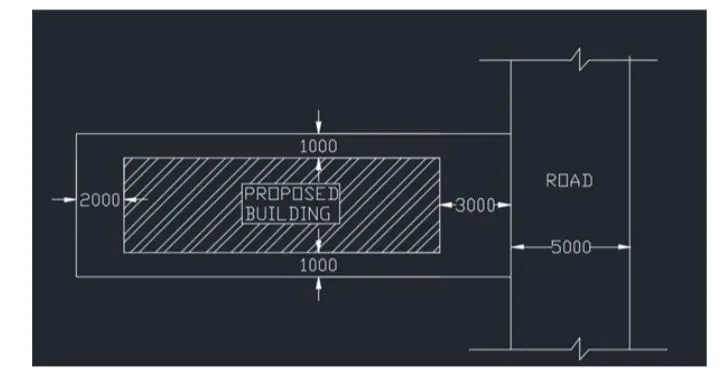
- Selection of Layers :
- Click on layer properties
- Click on new layer
- Give the layer name > Wall
- Turn the layer ON
- Set Unlock
- Slect layer colour > Red
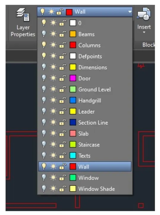
- Similarly, use this above process to provides the layer
- The layers which are assigned are shown in below fig
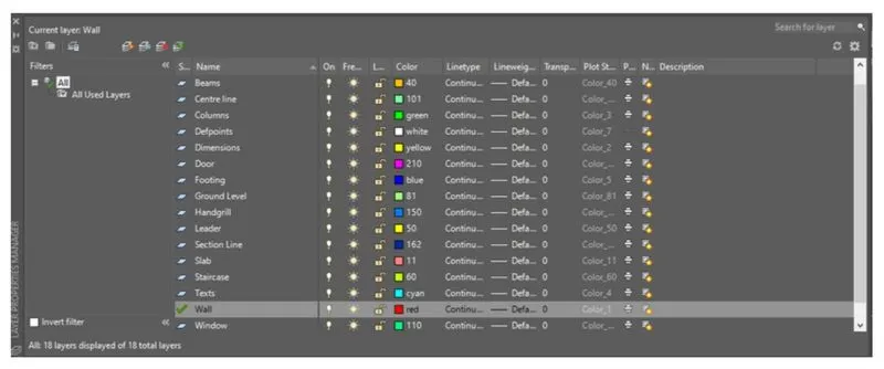
- PLAN
- We have the 13300mm X 4000 mm area on which the building is going to be built
- GROUND FLOOR PLAN
- Set the current layer to Wall
- Take the line command
- Specify first point > click anywhere on the sheet
- Specify next point > type 13300 > Enter by keeping curser rightside
- Specify next point > type 4000 > Enter by keeping curser upside
- Specify next point > type 13300 > Enter by keeping curser Lefttside
- Specify next point > type 4000 > Enter by keeping curser downside
- Enter
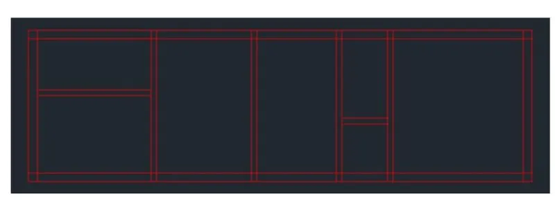
- Take offset command
- Specify offset distance > 230
- Click on all the lines on the screen > Keeping curser inside the lines to show the external wall thickness
- Specify offset distance > 3230 > Enter
- Specify object as > Left side vertical line
- Specify offset distance > 3380 > Enter
- Specify object as > Left side vertical line
- Specify offset distance > 5880 > Enter
- Specify object as > Left side vertical line
- Specify offset distance > 6030 > Enter
- Specify object as > Left side vertical line
- Specify offset distance > 8130 > Enter
- Specify object as > Left side vertical line
- Specify offset distance > 8280 > Enter
- Specify object as > Left side vertical line
- Specify offset distance > 9480 > Enter
- Specify object as > Left side vertical line
- Specify offset distance > 9630 > Enter
- Specify object as > Left side vertical line
- Specify offset distance > 13070 > Enter
- Specify object as > Left side vertical line
- Specify offset distance > 1580 > Enter
- Specify object as > Top Horizontal line
- Specify offset distance > 1730 > Enter
- Specify object as > Top Horizontal Line
- Specify offset distance > 2330> Enter
- Specify object as > Top Horzontal Line
- Specify offset distance > 2480 > Enter
- Specify object as > Top Horizontal Line
- It will gives you result as shown below
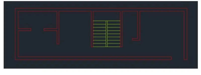
- Change current layer to staircase layer
- Take the offset command to show the staircase in plan
- Provide the tread of 250 by using offset command
- Take line command
- Select the mid of the tread line
- Extend this line by switchin On ortho mode to another end of the tread line to differ the flight
- Give offset at both side to that line at 50
- Select that line and erase it
- Take trim command
- Trim the internal lines of handgrill
- According to vaastu Shastra, Kitchen should be in a E-side or in a S-E side and living should be in a E-side or in a N-Side
- So kitchen and living room should be placed as per vaastu Shastra
- Use the Line command, Offset command and Trim command to leave the places for doors as shown below
- Set current layer to Door
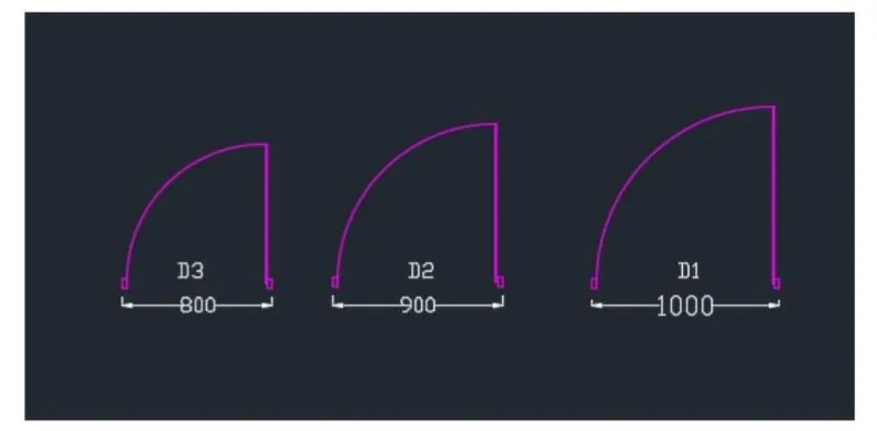
- To draft the doors D1
- Use the line command
- Specify point > anywhere in the drawing
- Specify length > @1000>0
- Take rectangle command to show the frame
- Specify length as 25
- Specify width as 50
- By using object snap move the rectangle at one end of the line and copy that rectangle and place over another end point of the line as shown below
- Take circle command to show the swing position of door
- Similarly draw the D2 and D3 as per above procedure
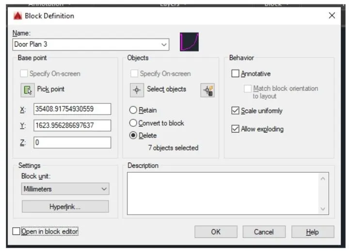
- To create a block for D1
- B > Enter
- Specify Name > Door 1 Plan
- Select object > Select D1 object
- Enter
- To create a block for D2
- B > Enter
- Specify Name > Door 2 Plan
- Select object > Select D2 object
- Enter To create a block for D3
- B > Enter
- Specify Name > Door 3 Plan
- Select object > Select D3 object
- Enter
- And made other internal settings as shown below
- To insert these blocks
- Take insert command
- Open Door 1 plan
- Select Scale > Specify on screen
- Select Rotation > Specify on Screen
- Enter
- Place the door as per requirement
- Specify scale > 1
- Specify Rotation angle > 0
- Similarly place the other doors as per requirement
- Use the line command and offset command to create the window and ventilators as per respective size
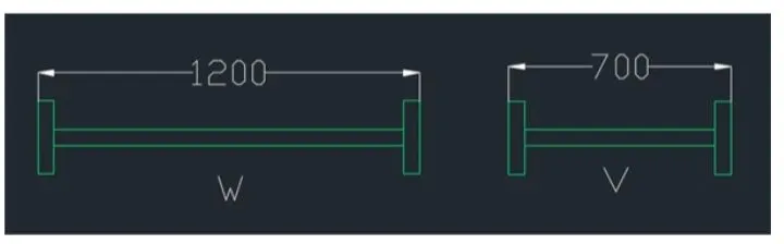
- To create a block for W
- B > Enter
- Specify Name > Window Plan
- Select object > Select W object
- Enter
- To create a block for V
- B > Enter
- Specify Name > Ventilator Plan
- Select object > Select V object
- Enter To create a block for V
- B > Enter
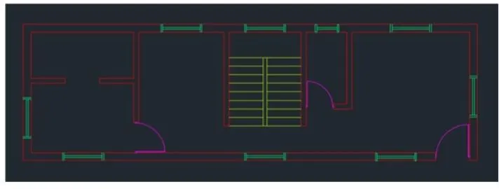
- Insert the window wherever it is necessary by the similar way as door
- It will show us following results
- For Hidden line
- Change the current layer to the staircase
- Click on line type > Other
- Load > Select ACAD_ISO03W100
- Global scale factor > 5
- Enter
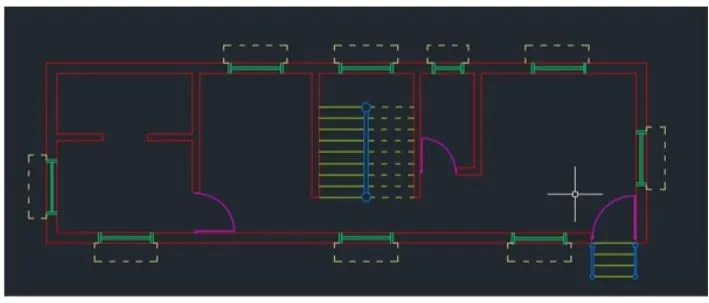
- Use line command to show the dashlines for the staircase as shown below
- Change current layer to Window shade
- Use the line command to provide the window shade as shown below
- To create the text
- Click on Annotation tab >multi line
- Manage textile > New
- Style name as > Project 1 > OK
- Font Name > Arial
- Height > 200
- And press set current
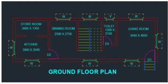
- Use multiline text
- And fill the required text in drawing as shown below
- Set current layer to dimension layer
- Click on ANNOTATION tab
- Click on Dimension
- Click > Manage dimension style
- Style name > Project
- Set the characteristics of dimensions as
- Select the yellow colour for the dimension style and extension line
- Select arrowhead size as 150
- Select the text as Cyan colour
- Select Text Style > Project 1
- Text Height > 150
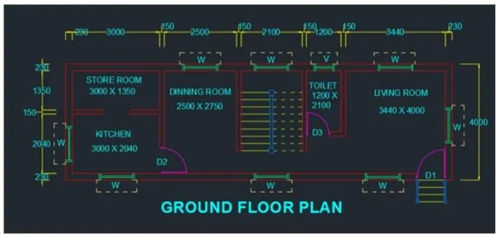
- Then select linear dimensions
- Provide the linear dimension having length 230mm
- Then take continuous dimension command and provide the dimensions
- And similarly this way, provide the dimensions wherever necessary
- To create the Leader
- Click on Annotation tab >Multileader
- Manage leader style > Project leader
- Maximum leader points 4
- Colour > Yellow
- Size > 100
- Text style > Project 1
- Text colour > Cyan
- Font Name > Arial
- Height > 200
- And press set current
- And fill the required text in drawing as shown below
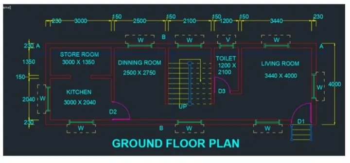
- Change the current layer to Section line
- Click on line type > Other
- Load > Select CENTER
- Global scale factor > 5
- Enter
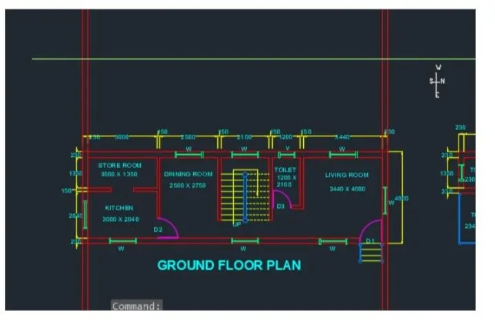
- The ground floor plan is ready
- First Floor Plan :
- Change the current layer to wall
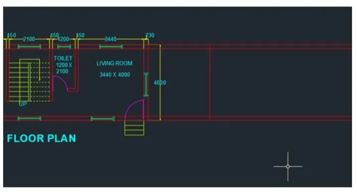
- Take the xline command
- Select > Horizontal
- Specify the points required to take projection for First floor plan
- Take the perpendicular line as shown below
- Take offset command
- Specify offset distance > 230
- Select the object > Click on perpendicular line
- Specify offset distance > 2430 > Enter
- Specify object as > Click on perpendicular line
- Specify offset distance > 2580 > Enter
- Specify object as > Click on perpendicular line
- Specify offset distance > 5880 > Enter
- Specify object as > Click on perpendicular line
- Specify offset distance > 6030 > Enter
- Specify object as > Click on perpendicular line
- Specify offset distance > 8130 > Enter
- Specify object as > Click on perpendicular line
- Specify offset distance > 8280> Enter
- Specify object as > Click on perpendicular line
- Specify offset distance > 9480 > Enter
- Specify object as > Click on perpendicular line
- Specify offset distance > 9630 > Enter
- Specify object as > Click on perpendicular line
- Specify offset distance > 13070 > Enter
- Specify object as > Click on perpendicular line
- Specify offset distance > 13300 > Enter
- Specify object as > Click on perpendicular line
- Trim and erase the unwanted lines
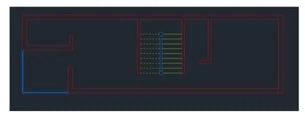
- Change current layer to staircase layer
- Take the offset command to show the staircase in plan
- Provide the tread of 250 by using offset command
- Take line command
- Select the mid of the tread line
- Extend this line by switchin On ortho mode to another end of the tread line to differ the flight
- Give offset at both side to that line at 50
- Select that line and erase it
- Take trim command
- Trim the internal lines of handgrill
- Change the layer to handgrill layer
- Selct the object and keep that object in handgrill layer
- For Hidden line
- Change the current layer to the staircase
- Click on line type > Other
- Load > Select ACAD_ISO03W100
- Global scale factor > 5
- Enter
- Use line command to show the dashlines for the staircase as shown below
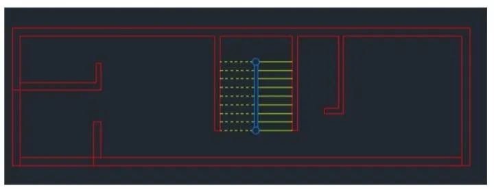
- Change the current layer to handgrill
- Provide the handgrills by using line command in Balcony
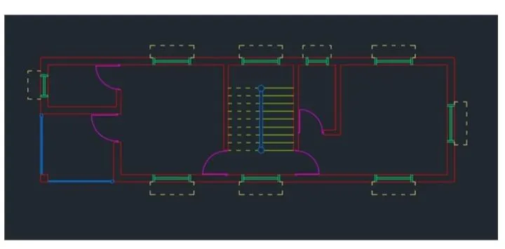
- Take insert command
- Open Door 1 plan
- Select Scale > Specify on screen
- Select Rotation > Specify on Screen
- Enter
- Place the door as per requirement
- Similarly place the other doors as per requirement
- Insert the window wherever it is necessary by the similar way as door
- Change current layer to Window shade
- Use the line command to provide the window shade as shown below
- It will show us following results
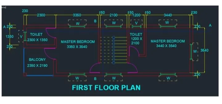
- To create the text
- Click on Annotation tab >multi line
- Style name as > Project 1 > OK
- Use multiline text
- And fill the required text in drawing as shown below
- Set current layer to dimension layer
- Click on ANNOTATION tab
- Click on Dimension
- Style name > Project
- Then select linear dimensions
- Provide the linear dimension having length 230mm
- Then take continuous dimension command and provide the dimensions
- And similarly this way, provide the dimensions wherever necessary
- The First plan is ready
- Elevation :-
- Change the current layer to wall
- Take the xline command
- Select > Vertical
- Specify the points required to take projection of Ground Floor plan for Elevation
- Change the current layer to ground level
- Take the perpendicular line as shown below
- Take the offset command
- Specify offset distance as 600 to show the plinth level
- Select object as > Click on the Ground level line
- Change the current layer to staircase
- Use the offset command to show the main entrance stairs having rise of 150 by keeping curser downwords
- Take the offset command
- Specify Distance as 3060
- Specify object > Click on plint level line keeping curser upside
- Specify Distance as 6120
- Specify object > Click on plint level line keeping curser upside
- Specify Distance as 7120 to show the parapet wall
- Specify object > Click on plint level line keeping curser upside
- Trim and erse the unwanted Xline
- It will show us following results
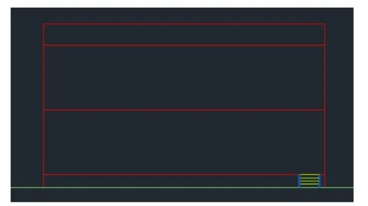
- To draw the door
- Change the current layer to door
- Take a Rectangle command
- Specify corner point anywhere out of elevation
- Click > Domension
- Specify Length as 1000
- Width as 2000
- Enter
- Explode command
- Select object as rectangle
- Take offset of 25 from both the vertical lines to show the frame
- Take offset of 25 from both the Top horizontal line to show the top frame
- Take offset from all the inside frames of 100
- Use the line command and offset command such that the top panel of the door will be of 750 X 1000 and bottom panel of 750 X 500 dimension created
- Enter
- The door is ready
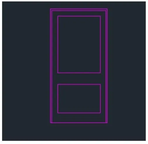
- Move that door and place in proper position as by using projection line from the ground floor plan
- Change the current layer to window layer
- Take projections from ground floor plan window by using x line command
- Take offset of plinth level line at a distance of 900 to show the window seal
- Tream and erase the unwanted lines
- Take offset command
- Specify distance as 50 and select the object > Click on all the four sides of window
- Draw the vertical line from the mid of horizontal line of window
- Take offset of that vertical line from both side at a distance of 50
- Similarly do the same process for all the windows
- Change the current layer to the wall layer
- Take the offset of left vertical line at a distance of 230
- Another take offset command
- Specifi object distance as > 2350
- Specify object > Click on left vertical line near the balcony
- Take the rectangle command
- Specify corner in the parapet wall
- Select > Dimension
- Length > 250 , Width > 500
- Enter
- Copy that rectangle > Array
- No of array > 8
- Fit as shown below
- Enter
- Take the rectangle command to show the window shade
- Specify corner point anywhere out of drawing
- Select > Dimension
- Length > 1400 , Width > 110
- Enter
- Take copy command
- Select object > Select rectangle
- And place that shade by keeping object snap ON
- Change current layer to text layer
- To create the text
- Click on Annotation tab >multi line
- Style name as > Project 1 > OK
- Use multiline text
- And fill the required text in drawing as shown below
- Click on ANNOTATION tab
- Click on Dimension
- Style name > Project
- Then select linear dimensions
- Provide the linear dimension as shown below
- Use the hatch command to give architectural look
- The elevation is ready
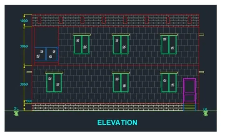
- Section AA :-
- Change the current layer to wall
- Take the xline command
- Select > Vertical
- Specify the points required to take projection of First Floor plan for Section
- Change the current layer to ground level
- Take the perpendicular line as shown below
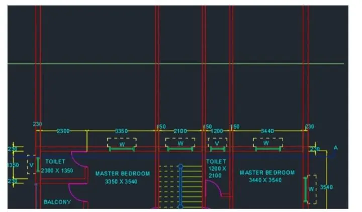
- Take the offset command
- Specify Distance as 3060
- Specify object > Click on plint level line keeping curser upside
- Specify Distance as 6120
- Specify object > Click on plint level line keeping curser upside
- Specify Distance as 7120 to show the parapet wall
- Specify object > Click on plint level line keeping curser upside
- Trim and erse the unwanted Xline
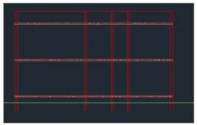
- Change the current layer to the slab layer
- Take offset command anf provide the slab depth as 110
- Take hatch command
- Click on dropdown
- Select hatch style as AR CONCR
- Scale > 50
- Click inside the slab portion
- It will show you following results
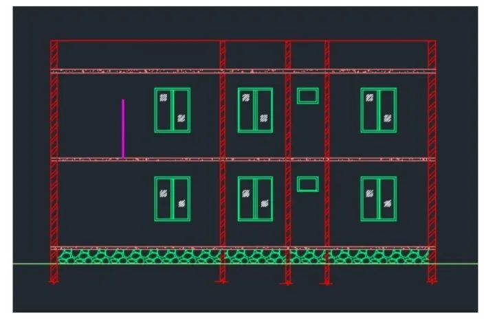
- Take the projections of windows from the first floor plan to show the windows and ventilatore
- Take a line command to show the jog for footing
- Take hatch command
- Click on dropdown
- Select hatch style as Gravel
- Scale > 600
- Click below the plinth line
- Take hatch command
- Click on dropdown
- Select hatch style as ANSI32
- Scale > 600
- Click inside the wall
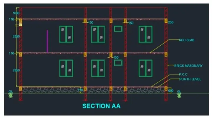
- Take rectangle command
- Specify corner > Anywhere out of section
- Specify > Dimension
- Specify Length > 230, Width > 350

- Copy this beam and provide at the required positions
- To create the Leader
- Click on Annotation tab >Multileader
- Manage leader style > Project leader
- Modify
- Maximum leader points 2
- And press set current
- And fill the required text in drawing as shown below
- Change the current layer to dimension layer
- Click on ANNOTATION tab
- Click on Dimension
- Style name > Project
- Then select linear dimensions
- Provide the linear dimension as shown below
- The section AA is ready
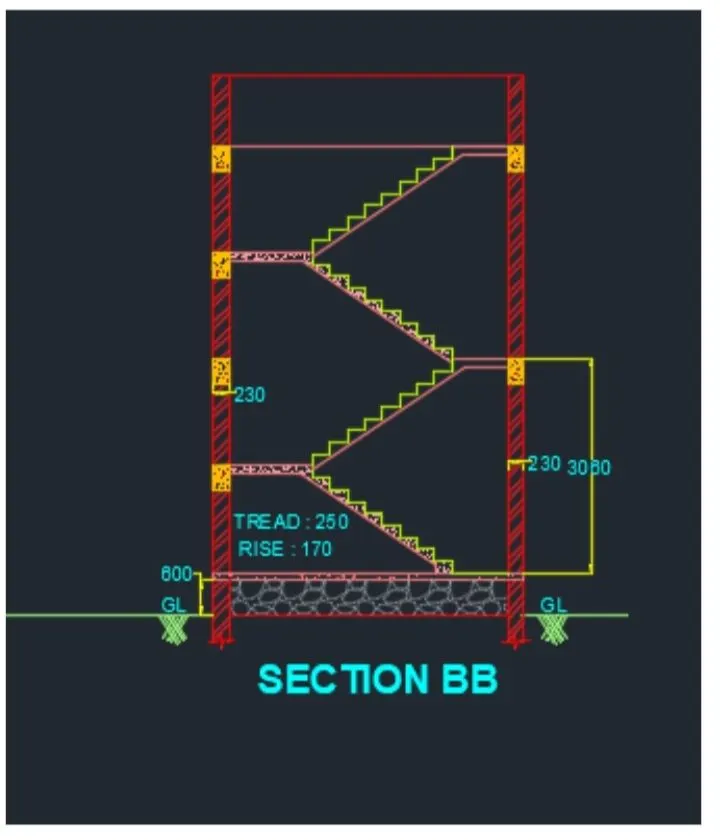
- Section BB :-
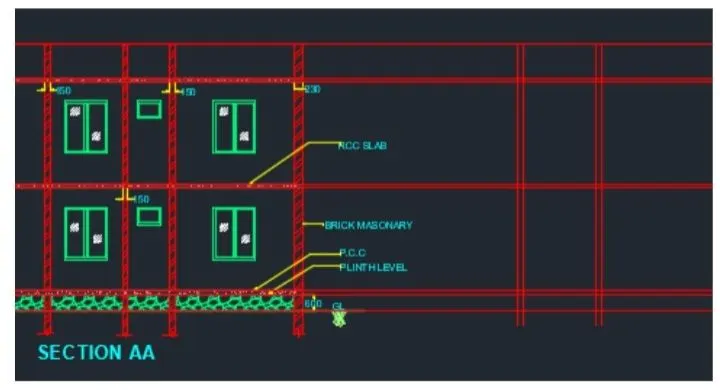
- Change the current layer to wall
- Take the xline command
- Select > horizontal
- Specify the points required to take projection of First Floor plan for Section
- Take the perpendicular line as shown below
- Take offset command
- Specify distance > 230 > Enter
- Specify object > Click on perpendicular line keeping curser rightside
- Specify distance > 4230 > Enter
- Specify object > Click on perpendicular line keeping curser rightside
- Specify distance > 4460 > Enter
- Specify object > Click on perpendicular line keeping curser rightside
- Enter
- Take a line command to show the jog for footing
- Trim and erase the unwanted xline
- Change the current layer to slab layer
- Take hatch command
- Click on dropdown
- Select hatch style as AR CONCR
- Scale > 50
- Click inside the slab portion
- Take hatch command
- Click on dropdown
- Select hatch style as Gravel
- Scale > 600
- Click below the plinth line
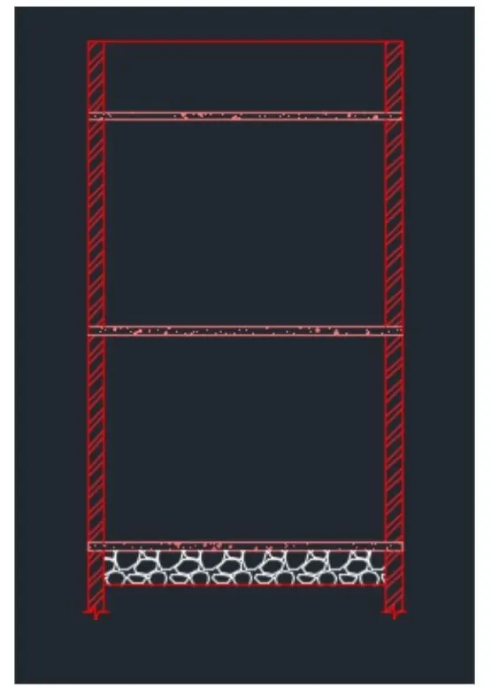
- Take hatch command
- Click on dropdown
- Select hatch style as ANSI32
- Scale > 600
- Click inside the wall
- Change current layer to staircase layer
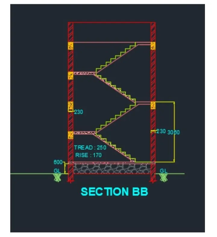
- Take offset of Right side internal vertical line of distance 800
- Take the line command
- Specify point > Click on the end of the last offset
- Specify next point > @170>90
- Specify next point > @250>180
- Specify next point > @170>90
- Specify next point > @250>180
- Continue this method upto the last step
- Take rectangle command
- Specify corner > Anywhere out of section
- Specify > Dimension
- Specify Length > 230, Width > 350

- Copy this beam and provide at the required positions
- Change the current layer to slab layer
- Use the line command to provide the waist slab
- Change current layer to text layer
- To create the text
- Click on Annotation tab >multi line
- Style name as > Project 1 > OK
- Use multiline text
- And fill the required text in drawing as shown below
- Set current layer to dimension layer
- Click on ANNOTATION tab
- Click on Dimension
- Style name > Project
- Then select linear dimensions
- And provide the dimensions as per requirement
- The section BB is ready
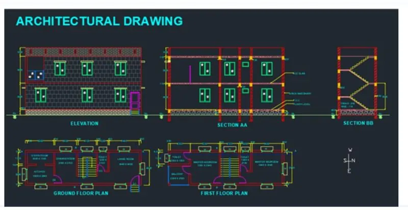
- The architectural Drawing is ready
- Strctural Drawing
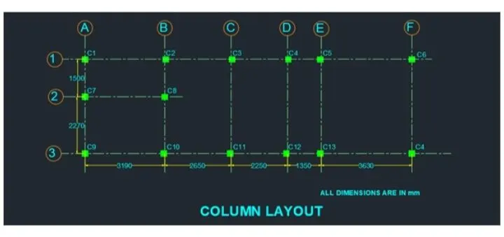
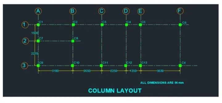
- Column Layout :-
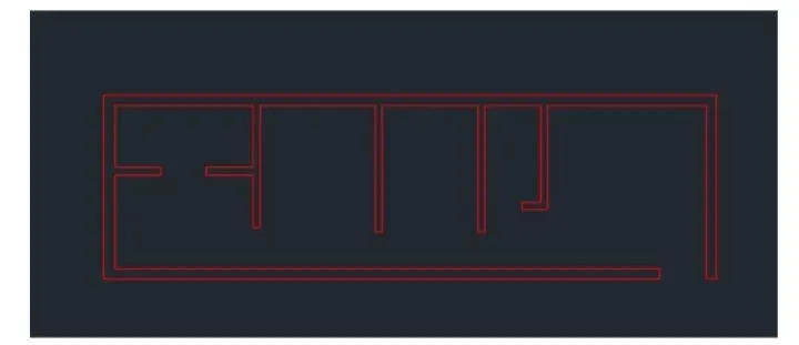
- Turn off all the layers except wall and column as per shown below
- Take copy command
- Select object > Select whole ground floor plan
- And place at a proper position as shown below
- For Center line
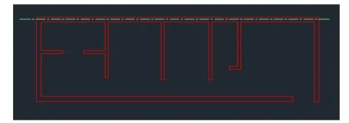
- Change the current layer to the center line layer
- Click on line type > Other
- Load > Select CENTER
- Global scale factor > 70000
- Enter
- Use line command
- Specify first point anywhere perpendicular of length 115to the internal wall
- Enter
- Again take line command
- Draw a line perpendicular to the last line drawn
- Enter
- Erase the first center line as per shown below
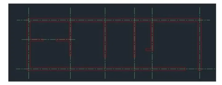
- By this similar way, draw the centre line for all the necessary walls
- It will show us the following result
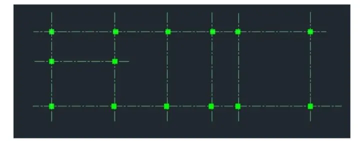
- Change current layer to column layer
- Take rectangle command to show the column
- Specify corner point anywhere
- Specify > Dimension
- Length > 230, Width > 230
- Take hatch command
- Click on dropdown
- Select hatch style as Solid
- Click inside the rectangle
- Copy that rectangle and place in location as per design requirement
- Off the layer of the wall , it will show us following result
- Mark the grid lines as 1,2,3 in Y direction and A,B, etc in X direction
- Create the circle and insert these above text and place as per shown below
- Also use the text command to show the C1, C2, etc
- Change current layer to dimension layer
- Click on ANNOTATION tab
- Change the layer to dimension layer
- Click on Dimension
- Click > Manage dimension style
- Style name > Project
- Then select linear dimensions
- Provide the linear dimension having length 3190mm
- Then take continuous dimension command and provide the center to center dimensions
- And similarly this way, provide the dimensions wherever necessary
- The Column layout is ready
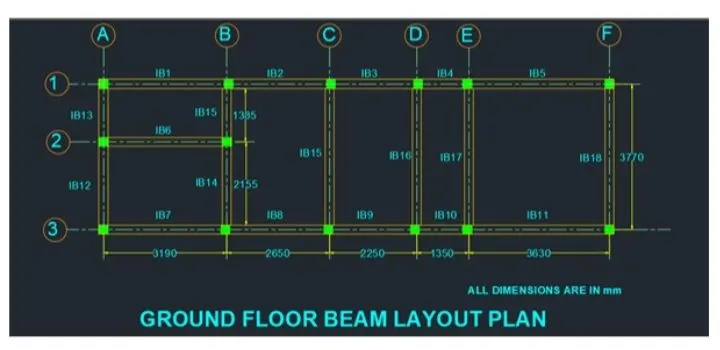
- Beam Layout :-
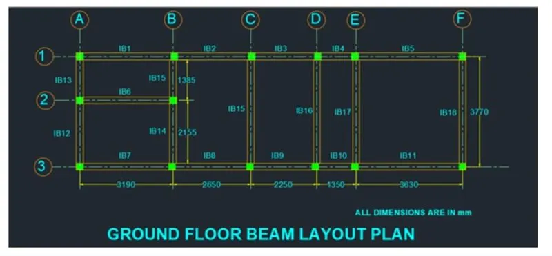
1. Ground Floor Beam Layout :-
- Keep all the layers off except centreline layer
- Copy the column layout drawing as drwn before
- And place to a proper position for showing beam layout using copied drawing
- For beam
- Switch ON beam layer
- Change the current layer to the beam layer
- Enter
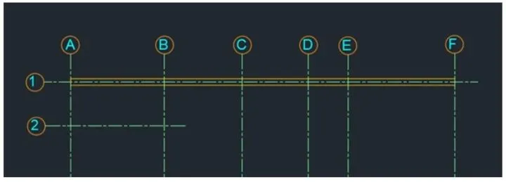
- Use line command
- Specify first point anywhere perpendicular of length 115to the center line
- Enter
- Again take line command
- Draw a line perpendicular to the last line drawn
- Offset this line at a distance of 230 to show the beam
- Enter
- Erase the first line as per shown below
- Similarly using this procedure, provide the other beams as shown below
- Switch on the column layer
- Change current layer to text layer
- To create the text
- Click on Annotation tab >multi line
- Style name as > Project 1 > OK
- Use multiline text
- And fill the required text to show the beam name such as IB1, IB2, etc in drawing as shown below
- Click on ANNOTATION tab
- Click on Dimension
- Click > Manage dimension style
- Style name > Project
- Then select linear dimensions
- And show the dimensions as shown below
- The Beam layout for ground floor is ready
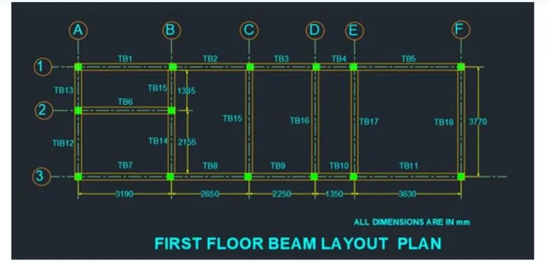
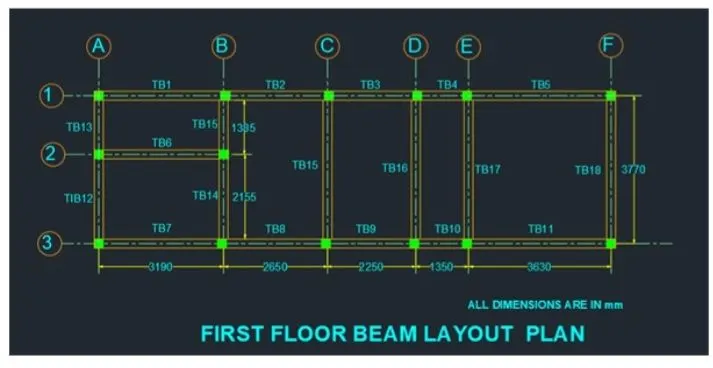
2. First Floor Beam Layout Plan :-
- Keep all the layers off except centreline layer
- Copy the column layout drawing as drwn before
- And place to a proper position for showing beam layout using copied drawing
- For beam
- Switch ON beam layer
- Change the current layer to the beam layer
- Enter
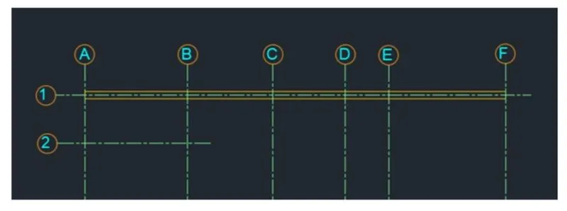
- Use line command
- Specify first point anywhere perpendicular of length 115to the center line
- Enter
- Again take line command
- Draw a line perpendicular to the last line drawn
- Offset this line at a distance of 230 to show the beam
- Enter
- Erase the first line as per shown below
- Similarly using this procedure, provide the other beams as shown below
- Switch on the column layer
- Change current layer to text layer
- To create the text
- Click on Annotation tab >multi line
- Style name as > Project 1 > OK
- Use multiline text
- And fill the required text to show the beam name such as IB1, IB2, etc in drawing as shown below
- Click on ANNOTATION tab
- Click on Dimension
- Click > Manage dimension style
- Style name > Project
- Then select linear dimensions
- And show the dimensions as shown below
- The Beam layout for First floor is ready
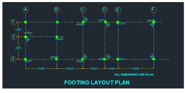
- Footing Layout :-
- Make off all the layers except column layer, text layer and center line layer
- Copy the column layout drawing
- And place at the side to create the footing layout drawing
- Switch on the footing layer and set current
- Take a rectangle command for the single footing
- Specify cornere > anywhere
- Specify > dimension
- Length as 1000 and width as 1000
- Take a rectangle command for the combined footing
- Specify cornere > anywhere
- Specify > dimension
- Length as 1000 and width as 2500
- Copy and Place the footing as per design requirement
- And rotate wherever it is necessary
- Switch on the dimension layer
- select current
- Click on ANNOTATION tab
- Click on Dimension
- Click > Manage dimension style
- Style name > Project
- Then select linear dimensions
- And show the dimensions for footing
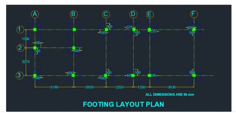
- The Footing layout drawing is ready
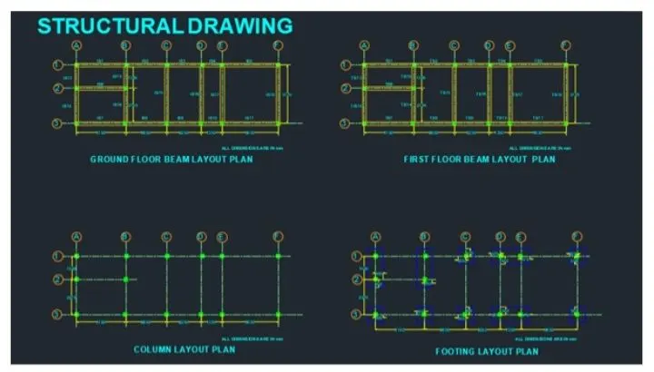
- The Structural Drawing is ready
- Result :-
- Architectural Drawing :-
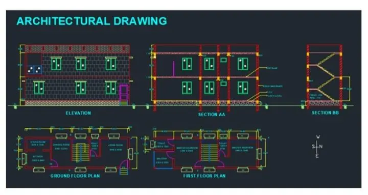
1. Ground Floor Plan :-
2. First Floor Plan :-
3. Elevation :-
4. Section AA :-
5. Section BB :-
- Structural Drawing :-
1. Column Layout Plan
2. Ground Floor Beam Layout Plan
3. First Floor Beam Layout Plan
4. Footing Layout Plan
Architectural and Structural Drawing