Project 1 _Creating an Architectural plan for the provided plot size and develop relevant basic structural drawings
Design and Draft a layout of a residential building with the following details:
a. Plot Size: 60’x20’(18.3m x6m)
b. Orientation- Facing East
c. Develop the following:
1. Architectural Drawing (Floor Plan, Elevations, and Sections)
2. Structural Drawing (Column, Bean, Footing Plan)
Aim: To draw:
1. Architectural drawing of a residential building:
- Plan of a residential building.
- Elevation of a residential building.
- Section of a residential building.
2. Structural drawing:
- Column plan layout of the building.
- Footing plan layout of the building.
- Beam plan layout of the building.
Commands used:
- Line.
- Offset.
- Rectangle.
- Trim.
- Extend.
- Block.
- Block edit.
- Dimension.
- Layer.
- Hatch.
- Design centre.
Procedure:
Step 1:
Opening of AutoCAD, setting limits .Select metric as we are drawing in Meters.
Set the limits and zoom all (Command -Z-a).Set the dimension to decimal units and set the precision.
Architectural drawing of residential building
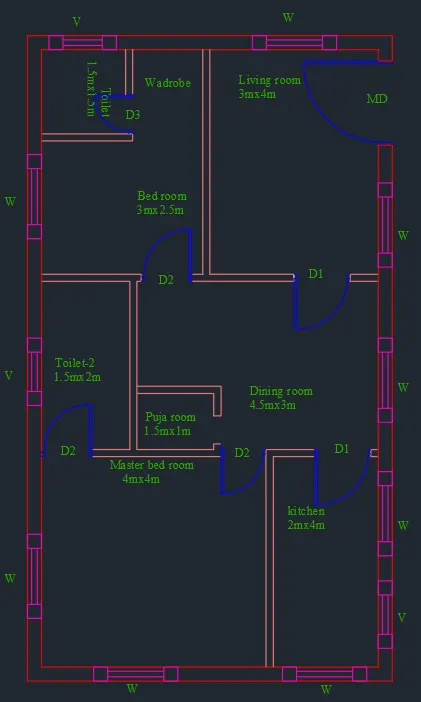
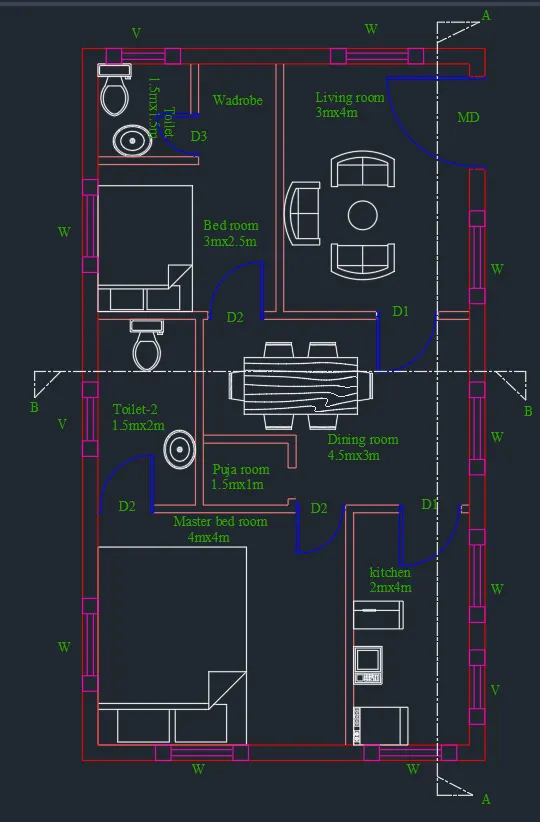
Plan of the residential building:
Step 2:
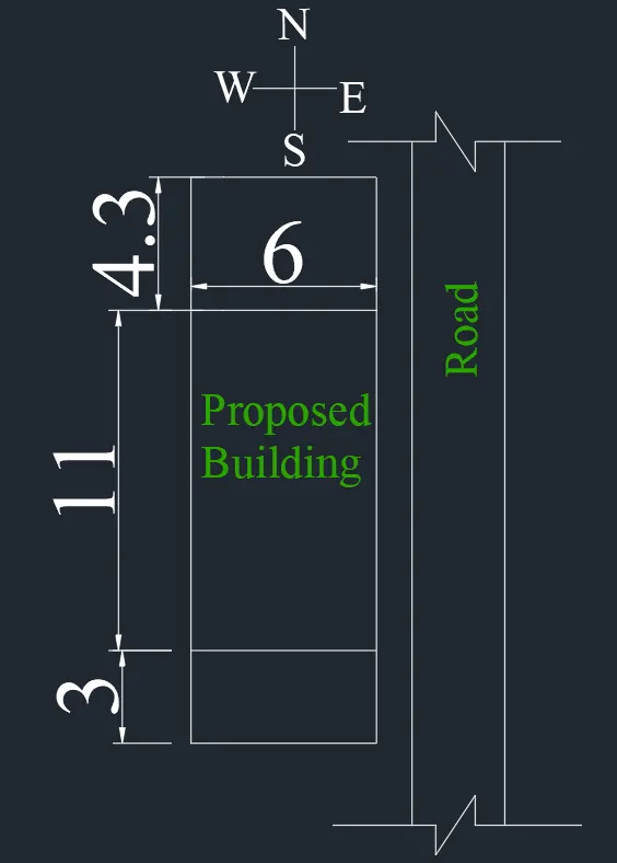
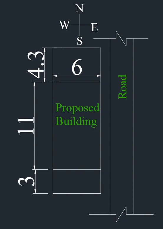
Drawing the plot, and giving setback.Given plot size as 18.3m x6m.Mark the direction N, S, E, W.
By rectangle, draw the plot giving dimensions as 6 and 18.3 m.
Give setback from the plot, 4.3m and 3m for the sides.The proposed building should come inside the setback drawn.
Drawing of plan:
Step 3:
Drawing wallOffset 0.25 m from the boundary after the setback is taken for the wall thickness.
Step 4:
Drawing Living room:
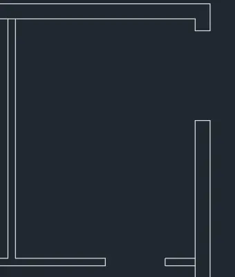
As the orientation is given as East, main door should face East.For living room, give 3m offset horizontally from the West side.
The size of the room will be 3 x 4 m.
Opening for main door is create by offsetting 1.5m from the wall and trim the same.
As per Vaastu Shastra, North-East is favourable for living room and the entrance should face North or East.
Step 5:
Drawing dining room:
Again offset 3m from the living wall for dining room.Width will be 4.5m
Size of dining room is 4.5x 3 m.Create a door opening of 1m on the North wall of living.

Step 6:
Drawing kitchen:
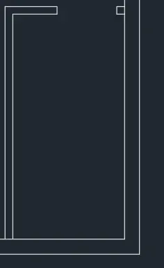
Offset 2m horizontally from dinning wall and 4m vertically.The size of kitchen is 2 x4 m.
Trim 1 m for the door opening.
According to Vaastu Shastra the ideal position for kitchen is South-East ,with cooking place facing East.
Step 7:
Drawing Master bedroom and toilet:
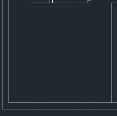
From the South wall offset 4m and width of 4m joining the kitchen wall.
The size of bedroom is 4x 4m.Create opening of 0.80 m by offset and trim commands.
For toilet, draw an offset horizontal of 1.5 m from the Dinining wall.
Size of toilet is 1.5 x2m.
North-East should be avoided for toilets according to Vaastu Shastra
According to Vaastu Shastra the ideal position for Bed room is South-West.
Step 8:
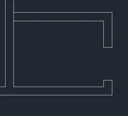
Drawing of Puja room:
From the Toilet offset 1.5m and from master bed room offset 1m.
Size of the puja room is 1.5m x1.0m.
North-East should be good for puja room according to Vaastu Shastra
Step 9:
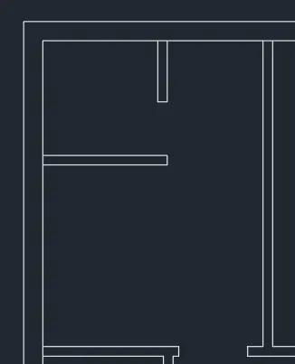
Drawing of Bed room with toilet:
From Living room offset 3m and from dining room offset 2.5m .Size of the bed room is 3m x 2.5m.
Draw a toilet of 1.5m x 1.5m inside the bed room.
Trim the excess lines and fillet the corners.
According to Vaastu Shastra for bed room is North-East good.
Step 10:
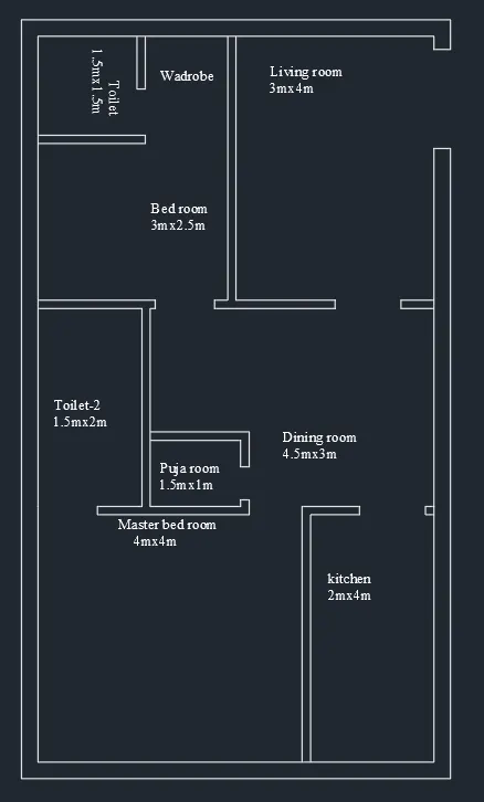
Inserting text:
With multiline text, draw the text box, text height as 0.15m and style as Times roman.
Step 11:
Place the doors and windows in the respective places.
Step 12:
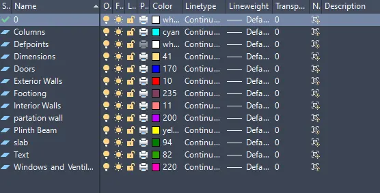
Use of Layer:
Different layers are made and the objects are placed in layers.Click on layer, layer manager dialogue box appears.
Create new layer button and create the layer for walls, stairs, doors, windows, text, dimension.Insert the respective elements in the layer.
Step 13:
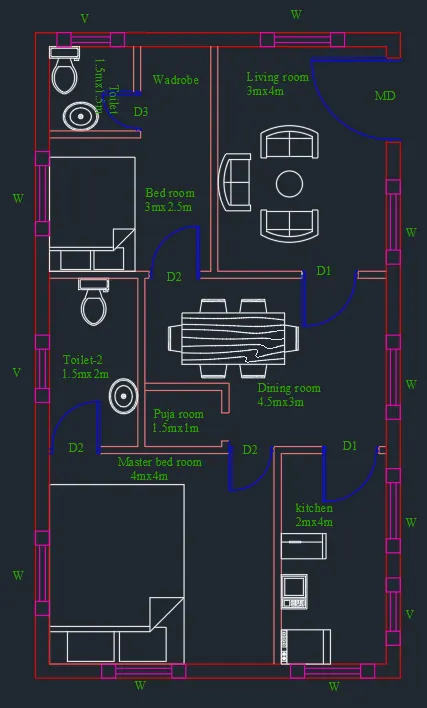
Design centre:
With the help of design centre, insert the required furniture in the plan.
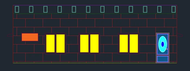
Elevation:
Step 14:
Projecting lines to draw the elevation.Project the wall lines to the top.
Draw a horizontal line.Offset 1 m for the plinth level.Offset 2.1m for the Lintel level.Offset 3.5m for the floor level .Offset 0.6m for the parapet wall .
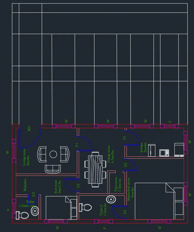
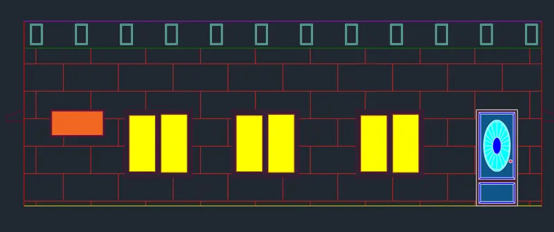
Trim off the extension lines and make shutters and panels for doors and windows.
For architectural purpose, create some hatches.
Section:
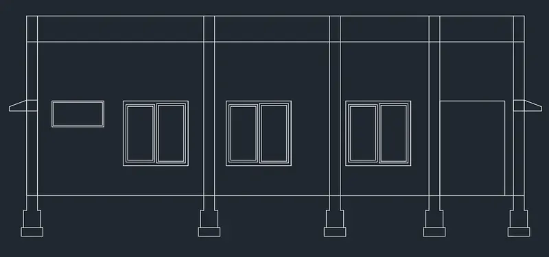
Step 15:
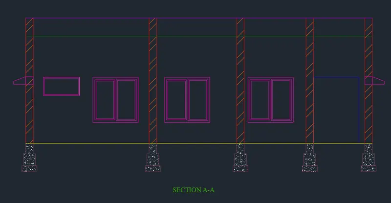
SECTION A-A:
Project the lines from the elevation for the height and from the section line of plan for the horizontal members.
Drawing windows, doors and stairs in section.Draw the window and door which we see after cutting the section line.
Trim off the unawanted lines.
Step 16:
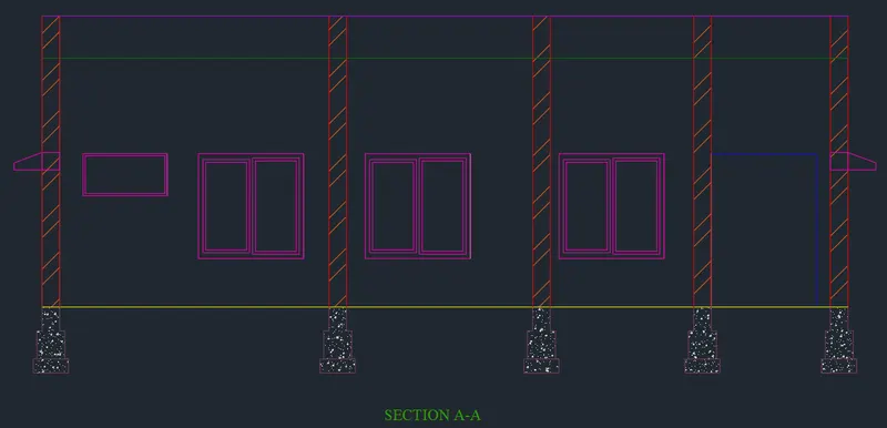
Hatching and layering:
Using hatch hatch the walls with the bricks hatch and foundation with the concrete hatch.
Place the windows and foundations in the respective layers and give colours.
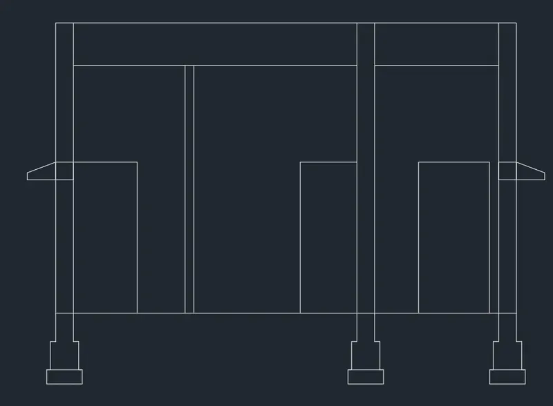
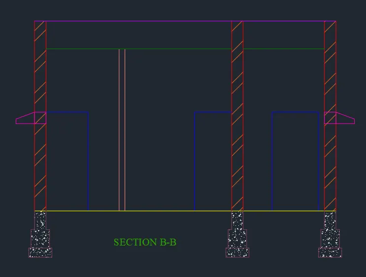
SECTION B-B:
Project the lines from the elevation for the height and from the section line of plan for the horizontal members.
Drawing windows, doors and stairs in section.Draw the window and door which we see after cutting the section line.
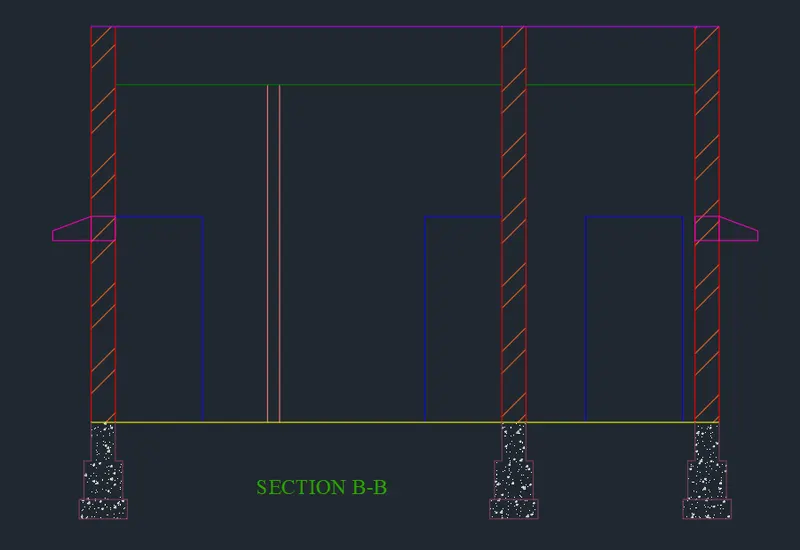
Using hatch hatch the walls with the bricks hatch and foundation with the concrete hatch.
Place the windows and foundations in the respective layers and give colours.
Structural drawings:
1. Column layout:
Step 17:
Placing of columns:
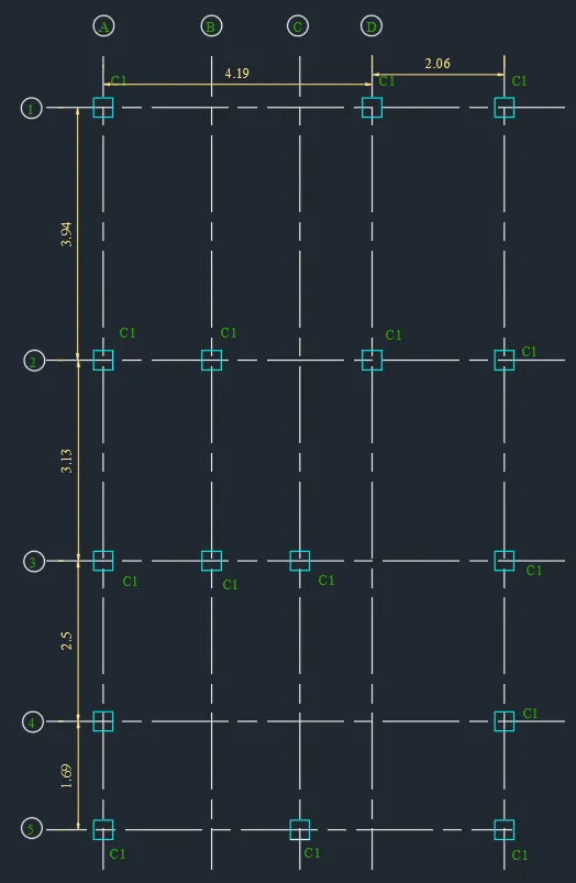
Column of size 0.25m x0.25m is considered.Columns are placed in all corners of the wall and intersection of walls wherever required.
Now draw the centre line for column from the annotate tab -centre line.
Now mark the grid line as 1,2 in the y direction and A, B, C, D, E, F in the x direction.
Create a circle and insert text into it .
Dimension between the grid lines is mentioned as it is used for marking the columns.
Make a layer for Column and place the column in that layer.
Footing Layout:
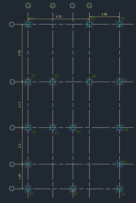
Isolated footing of size 0.5m x0.5m is provided.Create a rectangle with dimension 0.5x0.5 m, place the centre of rectangle with the centre of column.
Make a layer for footing and place the footings in that layer.
Plinth beam layout:
Drawing of plinth beam:
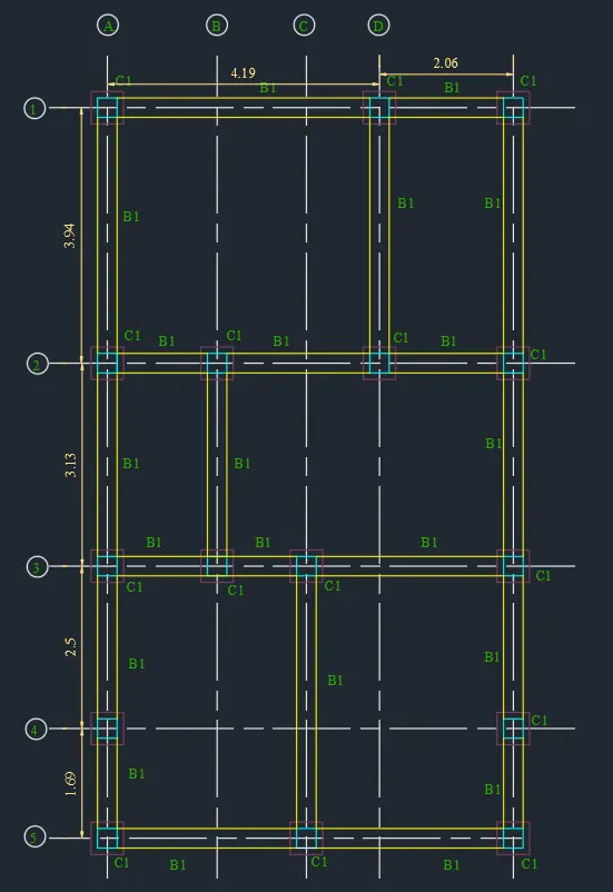
First connect the columns by beam of width 0.25m, as the wall thickness is 0.25.Plinth beam is provided below all the walls.
Create a layer for beam and put the plinth beam in that layer.
Result: Architectural and structural plan of a residential building is drawn.
1. Architectural plan is drawn:
Plot:
Plan:
Elevation:
Section A-A:
Section B-B:
2. Structural plan has been drawn:
Column Layout:
Footing Layout:
Plinth Beam Layout: