Project 1 _Creating an Architectural plan for the provided plot size and develop relevant basic structural drawings
AIM :- Design and draft a layout of residential building with the following details:
- Plot size – 60’x20’ (18.3m x 6m)
- Orientation – facing east
- Develop the following :
- Architectural drawing (floor plan, elevation and sections)
- Structural drawing (column, beam, footing plan)
INTRODUCTION :- AutoCAD is a commercial computer-aided design (CAD) and drafting software application. Developed and marketed by Autodesk, AutoCAD was first released in December 1982 as a desktop app running on microcomputer with internal graphics controllers. Before AutoCAD was introduced, most commercial CAD programs ran on mainframe computers or microcomputers, with each CAD operator working at a separate graphics terminal. AutoCAD is also available as mobile and web apps.
AutoCAD is used in industry, by architects, project managers, engineers, graphic designer, city planners and other professionals. It was supported by 750 training center worldwide in 1994.
USED TOOL COMMAND
- LINE, XLINE -To create plan sections, elevations, beam, column and footing layout.
- HATCH – To fill the column in column layout.
- RECTANGLE – To make column in column layout plan.
- COPY – To create same object at other place.
- OFFSET – To create the line at specific dimensions.
- DIMLINE/DIMCONTINUE – For mention all the dimensions.
- ARC – For creating doors.
- MTEXT – To write specific things which are required in drawings.
- QLEADER – To show staircase UP & DOWN.
- MIRROR – For drawing mirrored things.
- FILLET – To create rectangle where missed the lines.
- TRIM/ERASE – For trimming & erase all unwanted object or lines.
SIZE OF PLAN
- Given dimensions 60’x20’ (18.3m x 6m) converted into mm (18300mm x 6000mm) for drawing size which used in this
- The dimension assumed for the external wall 230mm and interior wall 150mm
- Main door D1 = 1000X2100mm
- D2 = 750X2100mm
- D3 = 900X2100mm
- W1 = 1500X1200mm
- W2 = 1200x1200mm
- W3 = 1000x1500mm
- V1 = 900X1200mm
- V2 = 600X600mm
- Stair = T.-200mm & R.-143.75mm
PROCEDURE :-
- Open AutoCAD by clicking on the AutoCAD icon on desktop.
- Start a new drawing by clicking CTRL+N on the keyboard. Create new drawing dialog box will appear.
- Click metric option and click OK.
- Type UN in command prompt and set units to decimal and set the precision as per data given and insertion scale as millimeters.
- Type LIMITS and specify lower corner as 0,0 and upper corner as 10000,10000.
- Type ZOOM and select ALL.
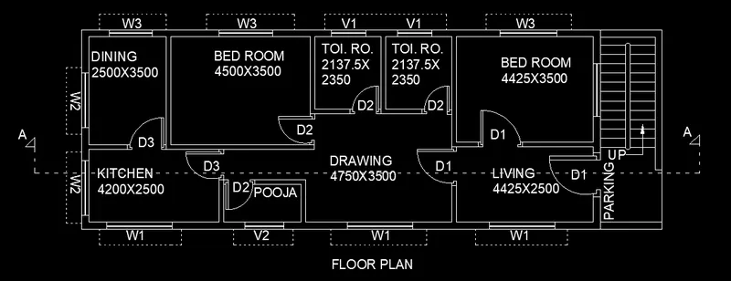
FLOOR PLAN
- XL command for horizontal and vertical line respectively for the starting reference corner.
- OFFSET command for offsetting line horizontally 6000mm for vertically 18300mm .
- OFFSET external wall as 230mm and internal wall as 150mm.
- Again by using OFFSET command for making rooms vertically and horizontally as shown size in drawing.
- For dinning room OFFSET horizontal from top 3500mm and for vertical line OFFSET from left 2500mm.
- For bed room-2 OFFSET horizontal from top 3500mm and for vertical line OFFSET from dinning 4500mm.
- For both toilet room OFFSET horizontal from top 2350mm and for vertical line OFFSET from bedroom-2 2137.5mm respectively for both.
- For bed room-1 OFFSET horizontal from top 3500mm and for vertical line OFFSET from toilet 4425mm.
- For living room OFFSET horizontal from bottom 2500mm and for vertical line OFFSET from right 4425mm.
- For kitchen room OFFSET horizontal from bottom 2500mm and for vertical line OFFSET from left 4200mm.
- For pooja room OFFSET horizontal from bottom 1200mm and for vertical line OFFSET from kitchen 1500mm.
- Remaining space is drawing area 4750x3500mm.
- After that draw doors and window and also the stairs by using LINE command and ARC
- MTEXT command used for show the rooms name and size
- For dotted lines change there line type at properties section.
- After that use the trim & erase tool to delete all unwanted lines and objects.
- QLEADER to show the staircase directions.
- For section-AA line is drawn by the line and properties changed to dotted line.
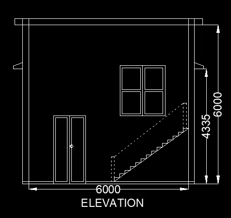
ELEVATION PLAN
- XL command for horizontal and vertical line respectively for the starting reference line from the plan.
- OFFSET & MIRROR command used to draw the door. At the distance of 1200mm from left and from right 3800mm.
- Door height 2100mm and width 1000mm.
- Window from the reference of plan 1500x1200mm.
- Stairs are drawn at the distance of 3000mm from left.
- chajja are made with the respective dimension.
- Stairs are drawn by using LINE command tread-200 and riser-143.75mm.
- For the dimensioning use DIMLINE
- For the text use MTEXT
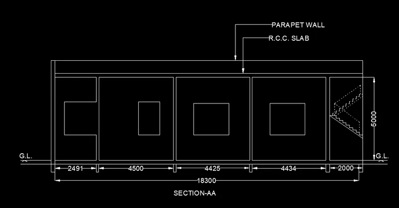
SECTION-AA
- XL command for horizontal and vertical line respectively for the starting reference line from the plan.
- Then by using OFFSET command drawn the line and windows.
- At the respective dimension which are shown above for all the objects.
- Stairs are drawn by using LINE command tread-200 and riser-143.75mm.
- TRIM command used to trim unwanted lines.
- For the dimensioning use DIMLINE
- For the text use MTEXT
- QLEADER for showing parapet wall & R.C.C. slab.
- Dotted stairs are drawn by LINE command then changed there properties to dotted line.
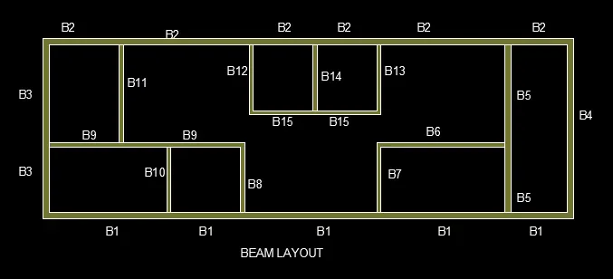
BEAM LAYOUT PLAN
- XL command for horizontal and vertical line respectively for the starting reference line from the plan.
- Then trimmed and erased unwanted lines by using TRIM & ERASE
- Then use the HATCH command to fill the beams.
- Solid color layer is used for hatching.
- MTEXT for showing the names of beam.
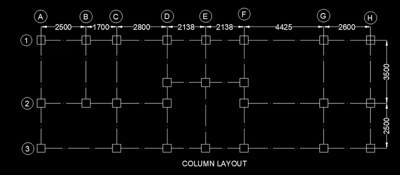
COLUMN LAYOUT PLAN
- XL command for horizontal and vertical line respectively for the starting reference line from the plan.
- Then make all the lines dotted from changing there properties from ribbon.
- Then draw rectangle 300x300mm.
- Then COPY object from there center then place at crossing point where I have to show columns.
- Then use MTEXT for numbering A-H and 1-3 then chose enclose circle from express tool.
- After making them block place where columns are shown.
- For the dimensioning use DIMLINE
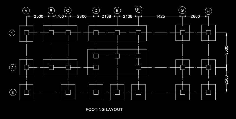
FOOTING LAYOUT PLAN
- XL command for horizontal and vertical line respectively for the starting reference line from the plan.
- Then make all the lines dotted from changing there properties from ribbon.
- Then draw rectangle 300x300mm.
- Then COPY object from there center then place at crossing point where I have to show columns.
- Show the columns as the footing where given as per the drawing.
- Footing are drawn by LINE command then COPY for other place where single footing.
- Footing are drawn by LINE command for showing two footing at same place.
- In center large footing which is drawn by LINE command at respective size.
- Then use MTEXT for numbering A-H and 1-3 then chose enclose circle from express tool.
- After making them block place where columns are shown.
- For the dimensioning use DIMLINE
RESULT :-
ARCHITECTURAL - The residential building is drawn to east facing direction with the given plot size. 20’x60’(18.3m x 6m) and the section and elevation are drawn as the same size which are plot is given.
FLOOR PLAN
ELEVATION PLAN
SECTION-AA
Structural drawing – The residential building is drawn to east facing direction with the given plot size. 20’x60’(18.3m x 6m) and the beam layout and column layout and footing layout plan are drawn as the respective size of floor plan.
BEAM LAYOUT PLAN
COLUMN LAYOUT PLAN
FOOTING LAYOUT PLAN