Project 1 _Creating an Architectural plan for the provided plot size and develop relevant basic structural drawings
Aim and Introduction
Aim:
This challenge aims to provide an experience to the student in sketching a full plan and elevation of a building including the column, beam and foundation details.. This will allow the student to utilize all the AutoCAD tools in multiple uses. The AutoCAD software provides different tools that when utilized together can from any sketch that followa in the imagination. A building part of the civil engineering industry and this correlates the AutoCAD software with the civil engineering industry. This challenge aims to give the student deeper understanding on how to utilize the AutoCAD software in sketching a residential building house. It provides the opportunity for the student to apply everything he have learned throughout the course
Introduction:
The AutoCAD software provides different tools. used in this challenge is as described below:
Line- creates line object
Polyline- creates rectangle line object
Rectangle- creates rectangles object
Circle- create circle object
Trim-Cut unwanted lines or shapes with the provided cutting edges
Extended- Extend lines to opposite corners
Move- Move objects to particular locations
Copy- Copy obejects to particular locations
Rotate- Rotate selected objects to a particular angle with respect to base point
Array- Copy an object in a set path linearly or polarly
Join- Joins separated line objects to a particular angle with respect to base point Dimlinear(DLI)- provides vertical or horizontal linear/ straight dimensions Dimligned(DAL)- Provides dimensions with respect to the angle of the object Dimangular(DAN)- Provides angular dimensions between two line objects.
Quicklinedimension(QDIM)-provides quick dimension of a geometry Leader- creates an arrow head line
Layer- Provides identification of line or object groups by their properties
Units- Open "Drawings Units" window to specify to modify the dimension properties
Hatch- provides hatching pattern in a given object or internal point
Sketch and Procedure:
A. 1st, 2nd, ad 3rd Floor Plan
Procedure:
Note: Units are in meter
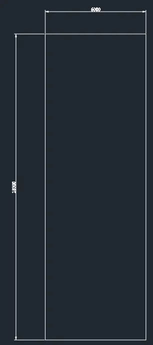
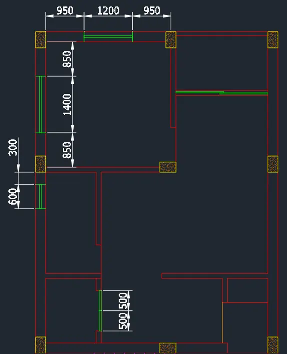
Create boundary using rectangle object. Dimension 6m by 18.3m
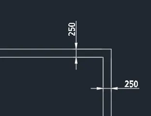
Offset it by 250 towards the inside to project the wall. Add the plant north facing east
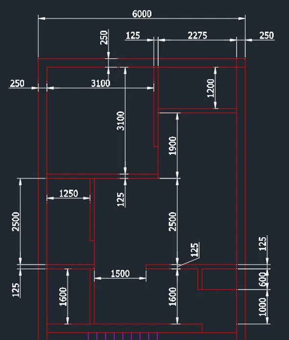
Now create a projected boundaries for the layout. Add lines and use the extend/trim command to sketch the plan
Start from the top, position stairs in the middle
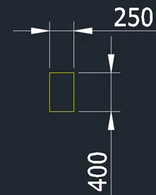
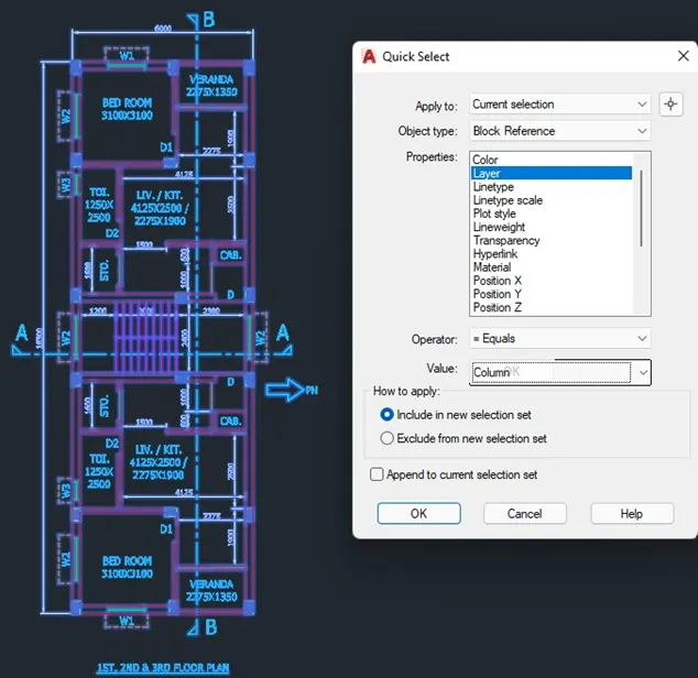
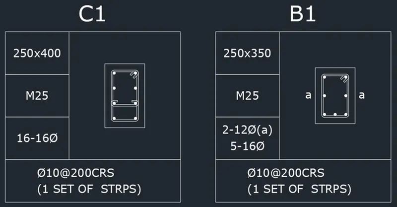
Add the columns. Column size is 250 x 400mm
Column Procedure
Put a hatch pattern inside and make it a block using the CTRL+C and CTRL+v function
Add the doors and windows at locations where it is needed
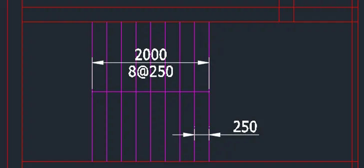
Create the stair provision at the middle part
Mirror the layout of the top room and mirror it on the other side. Include the columns,walls,windows and doors to the other side
Add the text at necessary dimension using the dtext command.Use dimlinear for the dimensions and utilize dimbreak for intersecting lines
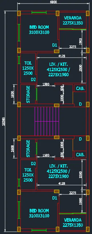
FINAL PRODUCT
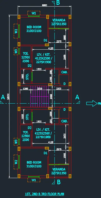
B. SECTION-AA PROCEDURE:
Project the plan to the elevation. Add the lines to represent the elevation and ground level
Use the Ray tool or XLINE tool to project the plan
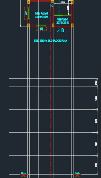
Draw the walls and columns through the projected lines. Do it per elevation
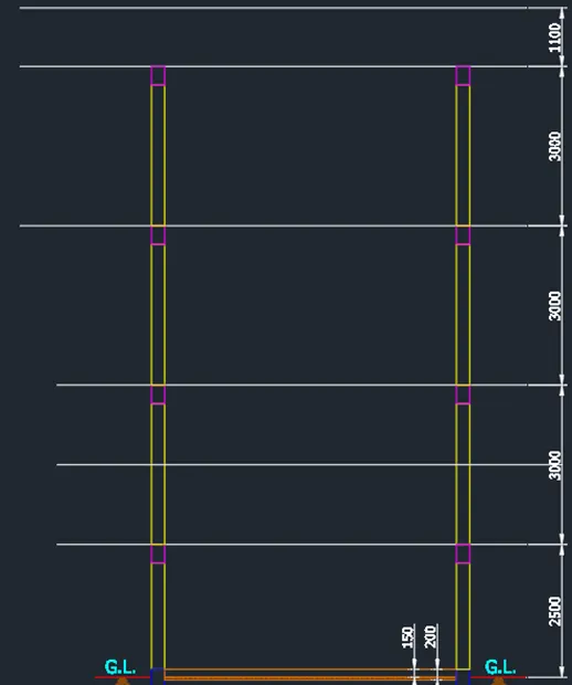
Create the stairs, use slab thickness= 125mm. Beam size is 250x350mm
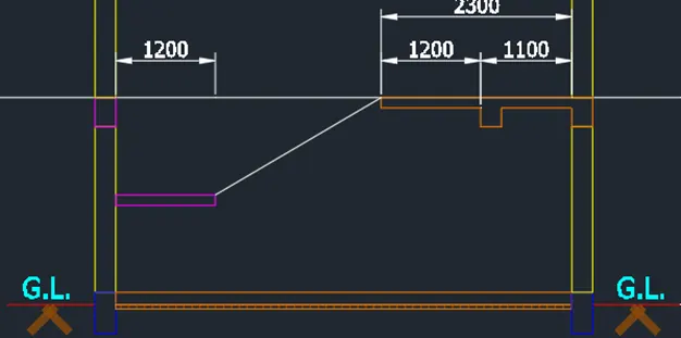
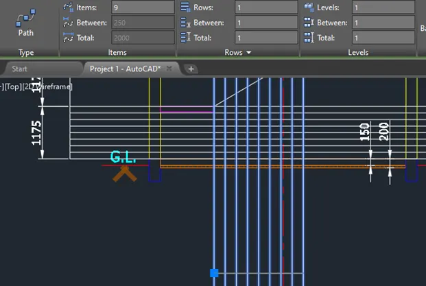

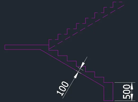
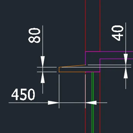
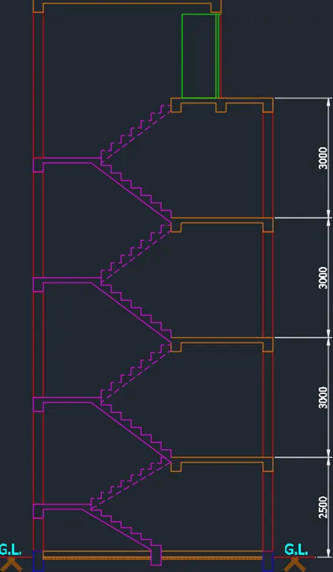
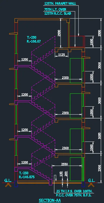
Add the doors and windows.Add the necessary texts and dimensions.Use dimlinear and simcontinue to proceed.Use dtext command and textheight 200 for the texts
Add arrows using the leader command at necessary spaces
Results
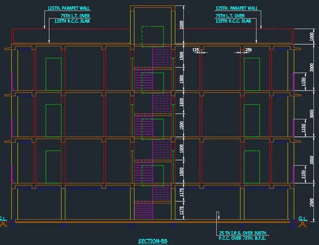
C. SECTION-BB
PROCEDURE:
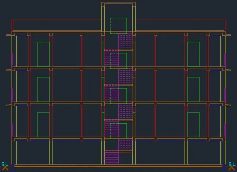
Project the plan and elevation using lines,ray or xline
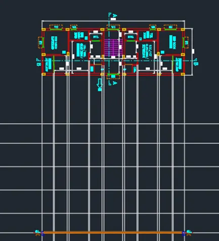
Draw the columns and walls. Draw it per level
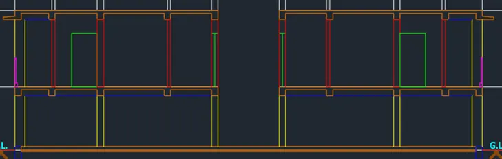
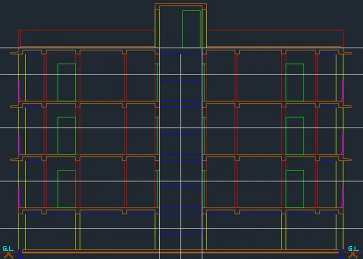
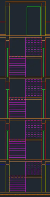
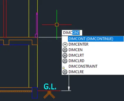
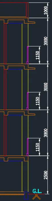
Add the text and dimension. Use dimlinear,dimcontinue and dtext to sketch this. Utilize leader to add the arrow
Results
D. Footing Plan
PROCEDURE:
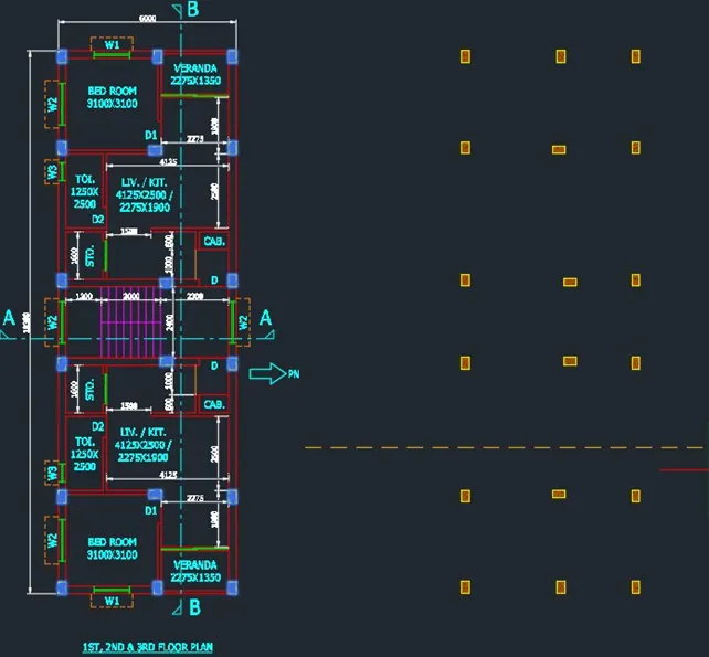
Copy the columns and add gridlines
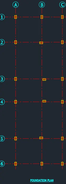
Add the dimensions
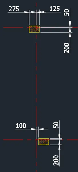
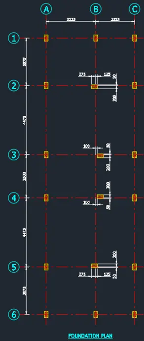
Add the footing boundary
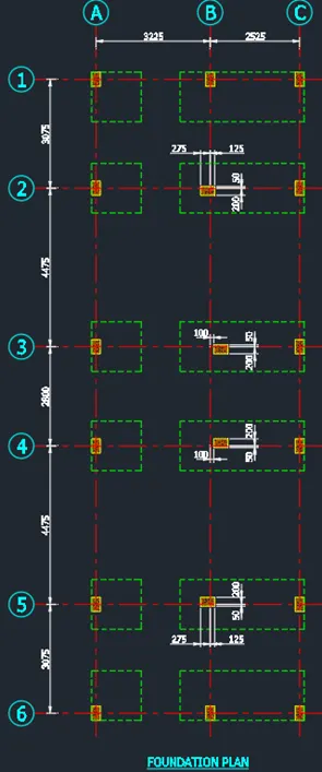
Add the footing dimensions to finish the plan
Result:
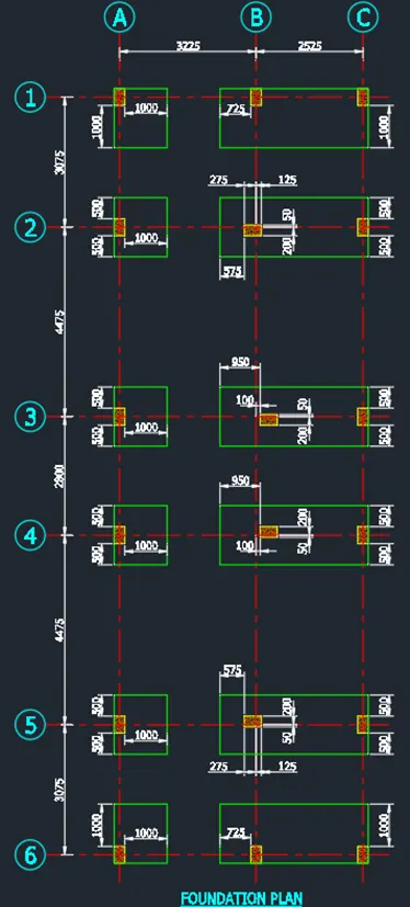
Column and Beam Details
PROCEDURE:
Create the column coundary
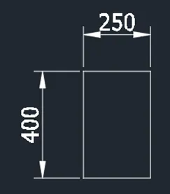
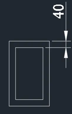
Add the ties. Concrete cover is 40mm
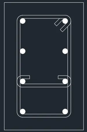
Add the rebars using circle command. Add a solid hatch for the main bars. Stirrups is 10mm and main bar is 16mm

Add the boundary and add the details using texts
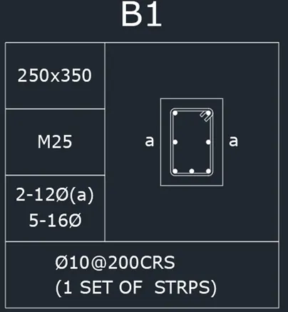
Results:
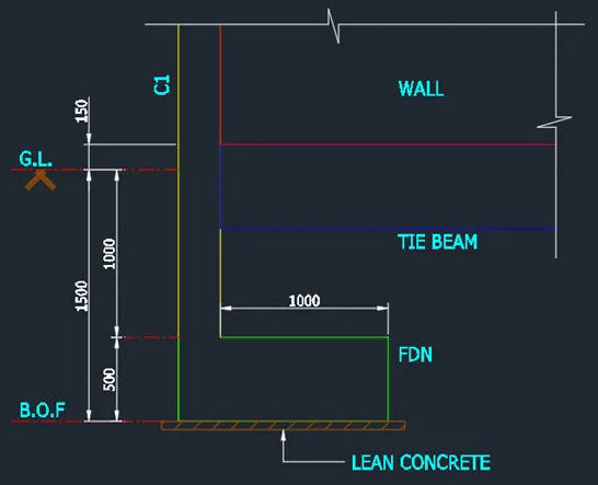
Footing Detail
PROCEDURE:
Copy the plan and project a typical footing detail
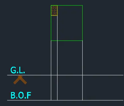
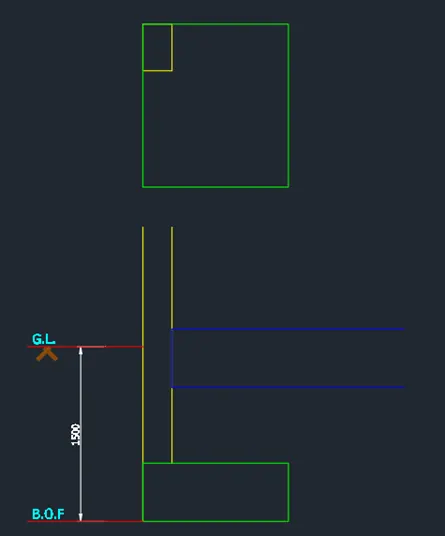
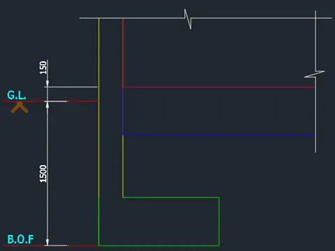
Add the necessary dimensions and texts
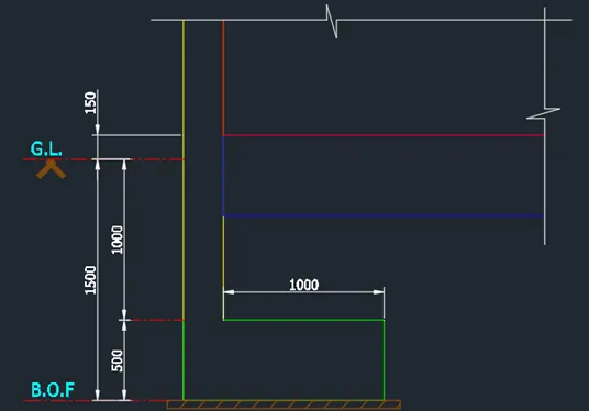
Results:
Conclusion:
AutoCAD software is a great tool for the civil engineering industry. The AutoCAD software contains a number of tools in helping to create,sketch, or draw building plans, elevations and details.By utilizing the different tools provided by this software, a civil engineer can provide the correct and accurate the actual image of the building but also provides the specific details of the building. The specific details contain the column/beam size,dimensions,reinforcement information,thickness and other important informations that is required in the construction of building
The AutoCAD software is revolutionary tool that makes the creation and production of construction drawings faster and easier.