Project 1 _Creating an Architectural plan for the provided plot size and develop relevant basic structural drawings
AIM:
Design and Draft a layout of a residential building with the following details:
a. Plot Size: 60’x20’(18.3m x6m)
b. Orientation- Facing East
c. Develop the following: 1. Architectural Drawing (Floor Plan, Elevations, and Sections) 2. Structural Drawing (Column, Bean, Footing Plan)
INTRODUCTION:
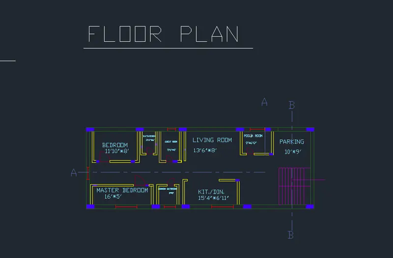
- specify command line to draw the plan
- set the measurement units as architectural in dimension style manager
- use trim command for any extend lines
- In layer properties apply layers to plan
- Cross-section the plan with the help of line command .
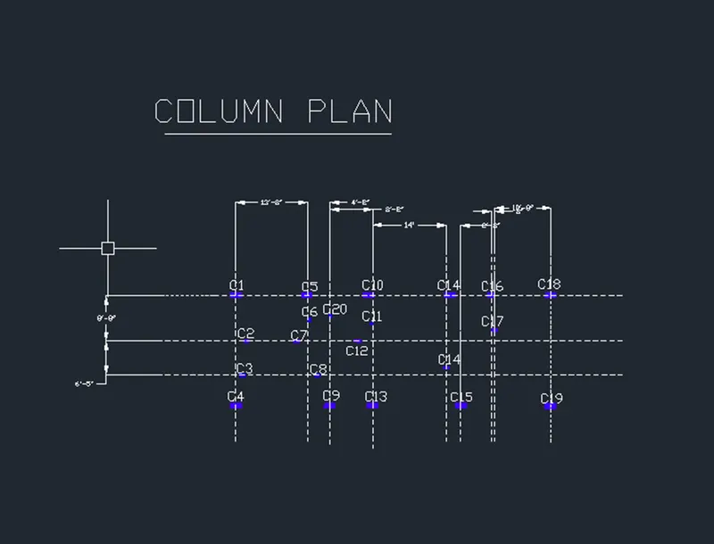
- With the help of layer option switch off the layer of walls, doors, windows, staircase, dimension text, section line
- Draw central line of the column horizontally and vertically through it.
- Measure the dimensions of each column using dimension options .
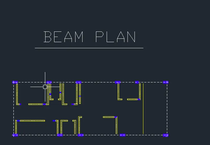
- With help of layer option switch off the layers like windows ,door, dimension text, section line , staircase.
- Draw a hidden central line crossing all the columns in walls.
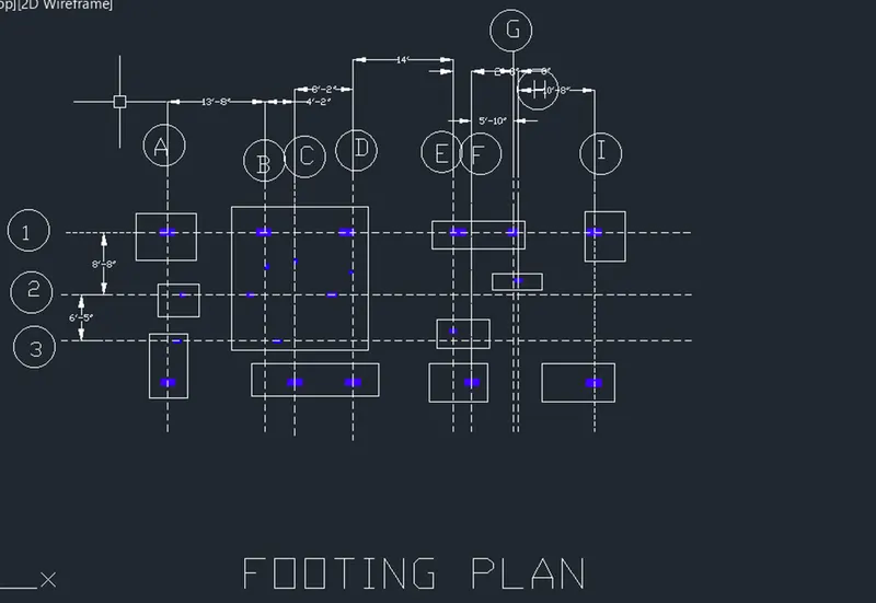
- With help of layer option switch off the layers like windows, door, dimension text, section line, staircase, walls.
- Draw a hidden central line touching the all columns horizontal and vertical.
- Specify rectangle command and draw the rectangles around the column edges.
- Take dimensions using dimension option between column lines.
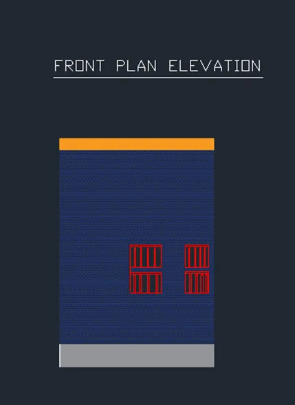
- Specify command XL line and draw the lines from column, windows intersecting the floor plan.
- Project the lines vertically downward and make a plan
- Draw a horizontal xl line presenting the NGL, plinth, sill and lintel .
- From the projections using trim command remove unwanted column lines .
- Create window by projections of window section.
- Apply layer filters and hatch to the lines created in the plan.
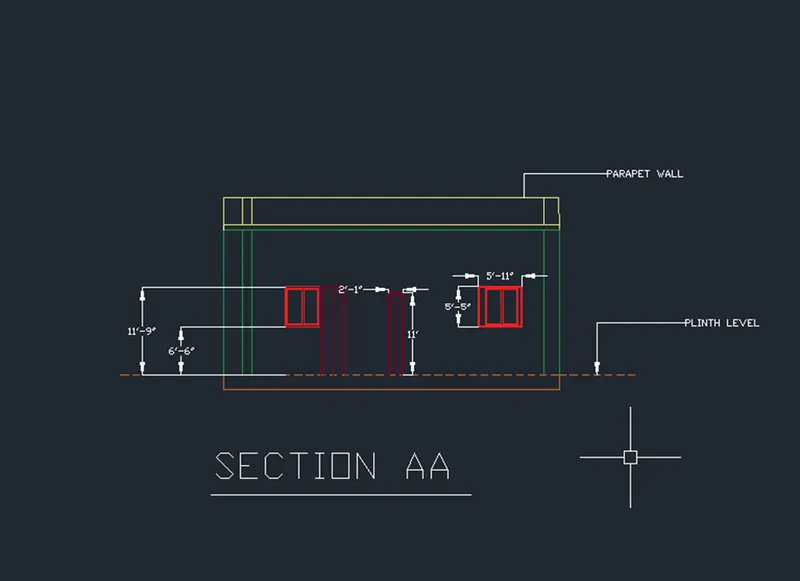
- Specify command XL line and draw the lines from column, windows ,door intersecting the floor cross -section plan AA.
- Project the lines vertically downward and make a plan
- Draw a horizontal xl line presenting the NGL, plinth, sill and lintel .
- From the projections using trim command remove unwanted column lines .
- From projection of window draw a vertical line and create a section window by trimming unwanted lines.
- Draw projection lines of door vertical and make door section by trimming unwanted line.
- Measure the distance between plinth and windows, door using dimension option.
- Apply layer properties to the lines.
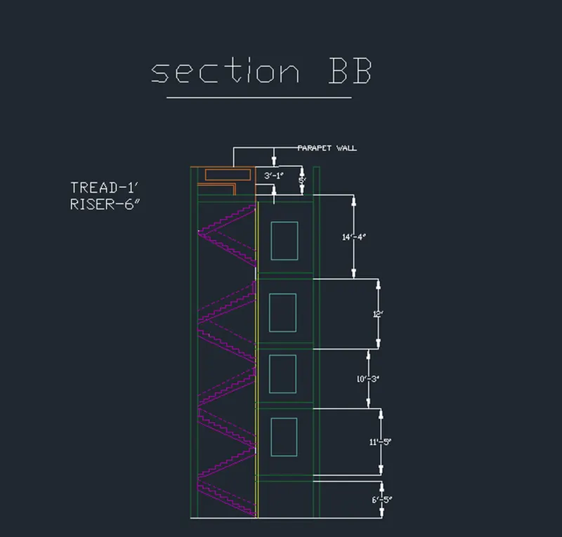
- Specify command XL line and draw the lines from column, stair case intersecting the floor cross -section plan BB.
- Create a sectional staircase from the stair case projection lines.
- Using trim command erase all unwanted lines.
- Draw rectangle showing the sectional room plan.
- Apply layer filters to the all lines .
- Measure the distance of section plan room elevation using dimension options.
https://web.autocad.com/acad/me/sid/shares/drawings/b9883754-97e9-4a0f-9cf0-e2685ff23eb5/editor