Project 1 _Creating an Architectural plan for the provided plot size and develop relevant basic structural drawings
AIM: To create the Architectural Drawing ( Floor plan, Elevations and Sections) for the plot size 60' X 20'(18.3m X 6m),orientation East facing and to develop various structural drawings ( Column, Beam, Footing plan).
INTRODUCTION: The desired drawing can be prepared by using different AutoCAD tools and commands like : Line command , Erase command , Circle command, Rotate command , Trim command, Rectangle command, Dimlinear command, Text command, XL command etc. These are the various tools which helps us in creation relevant drawings in the AutoCAD.
1. ARCHITECTURAL DRAWINGS:
Procedure:
- Firstly open the AutoCAD software select NEW.
- In the Create New Drawing option select IMPERIAL settings.
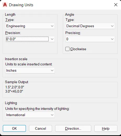
- In the advanced setup select the Engineering as the measurement unit and select precision as 0'-0.0".
- Now set the limits just by typing LIMITS in the command line and then press Enter.
- Now give the limits. The lower left corner limit is 0'0",0'0" and the upper right corner limit is 1000',1000'.
- Now set the unit just type UNI in the command line and then press Enter.
- Select the Engineering in the type section and give the precision as 0'-0.0" and Inches in the insertion scale column.
- Then click on OK.
Create layers:
- Firstly click on the LAYER PROPERTIES option in the layer pannel.
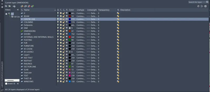
- Now click on the NEW LAYER to create the different layers for different blocks like doors, windows, external and internal wall,furniture,stairs,dimensions,text etc.
- Specify different colours for different blocks.
- And now close the layer properties.
A) Floor plan:
Given data:
Plot size: 60' X 20'. or (18.3m X 6m).
- To start the drawing,select the walls layer from the layer properties as the current layer.
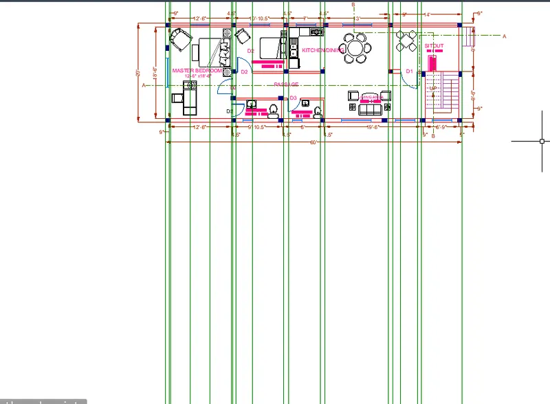
- With the help of Construction line command we can draw the boundaries of the plan.
- Type XL in the command line and then type "V" for the vertical line and "H" for the horizontal line and then press Enter.
- Draw two construction lines, one in horizontal and the other one is vertical in direction intersecting at a point.
- Now press ESC to cancel the xline command.
- By using trim tool we can trim the all unwanted lines. Just type TR in the command line and then press Enter.
- Now trim the all unwanted lines.
- Press ESC to cancel the ESCAPE command.
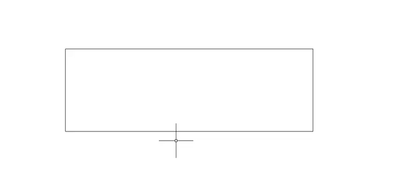
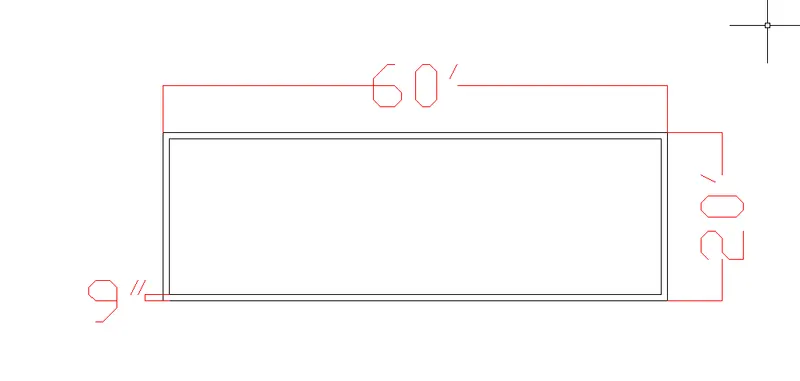
- Using offset command, offset the vertical line at a offset distance of 60'.
- And the horizontal line at a distance of 20'.
- Repeat the offset command to give the thickness of the walls.
- Take external thickness as 9" and internal thickness as 4.5".
- Select both the vertical and horizontal line above the drawing.
- Press ESC to cancel the OFFSET command.
- Now trim the all unwanted lines using the TRIM command.
- Type TR in the command line and the press Enter.
- Press ESC.
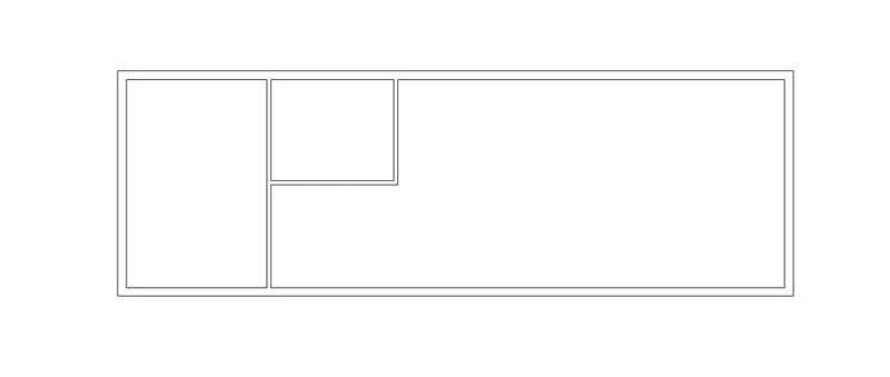
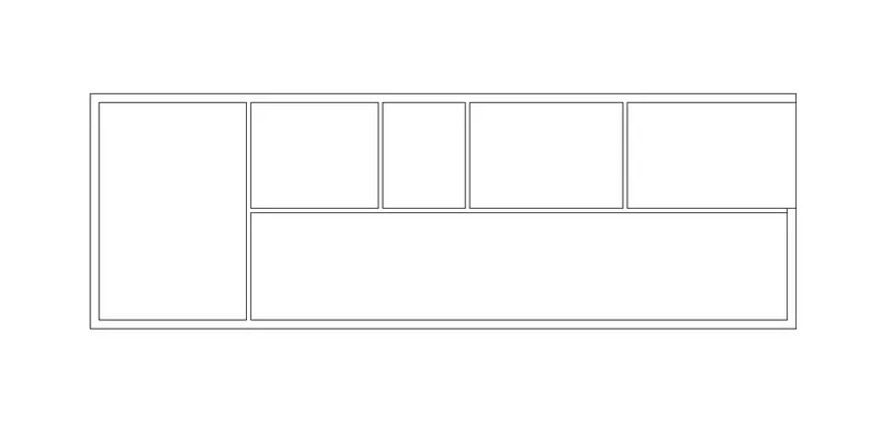
- Use the offset command repeatedly to create the remaining walls i.e,internal and external walls.
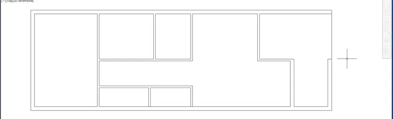
STAIRS:
- For drawing the stairs, select the stairs layer from the layer properties and turn on the stairs layer.
- Stairs can be drawn using the line command, type L in the command line and then press Enter.
- Draw a line of length 6'.
- Press ESC to cancel the line command.
- Now using the offset command we can draw the steps/treads of the stairs. Type OFFSET in the command line and then press Enter.
- Specify the offset distance as 10" and the click wherever is required.
- Now keep selecting and offseting the lines untill 9th step to create the staircase.
- Now press the ESC to cancel the offset command.
- Now using the line command draw a midline of 6" line.
- Press the ESC command to cancel the line command.
- Now use the trim command and trim the all unwanted lines.
- Type TR in the command line and then press Enter.
- Press Esc to cancel the trim command.
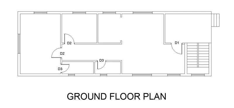
DOORS AND WINDOWS:
Assumed data:
DOORS:
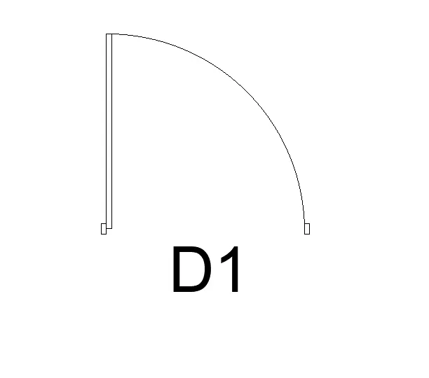
D1 : 3'-3" X 6'-8"
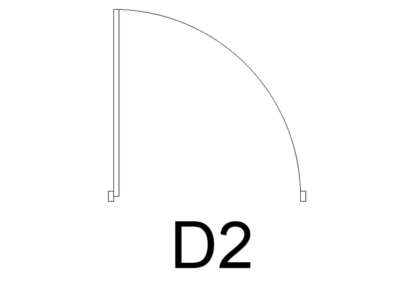
D2 : 3' X 6'-8"
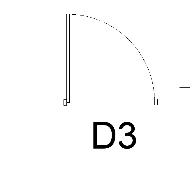
D3 : 2'-6" X 6'-8"
- To draw the doors and windows, select the door and window layer from the layer property.
- And set the door and window layer as the default layer.
- Using the line tool by typing L in the command line and then press Enter.
- Door D1 is created at the main door with a width of 3'-3".
- Press Esc to cancel the line command.
- Using the arc command i can draw the arc represents the swing of the door.
- Click on the arc option from the ribbon and from there click on the Start,End,Direction and draw the arc by specifying the start,end and direction.
- Press Esc to cancel the Arc command.
- Now using the line command by typing L in the command line and then press Enter.
- Door D2 is created with a width of 3'.
- Press Esc to cancel the line command.
- Using the arc command i can draw the arc represents the swing of the door.
- Click on the arc option from the ribbon and from there click on the Start,End,Direction and draw the arc by specifying the start,end and direction.
- Press Esc to cancel the Arc command.
- Now using the line command by typing L in the command line and then press Enter.
- Door D3 is created with a width of 2'-6".
- Press Esc to cancel the line command.
- Using the arc command i can draw the arc represents the swing of the door.
- Click on the arc option from the ribbon and from there click on the Start,End,Direction and draw the arc by specifying the start,end and direction.
- Press Esc to cancel the Arc command.
Assumed data:
WINDOWS:
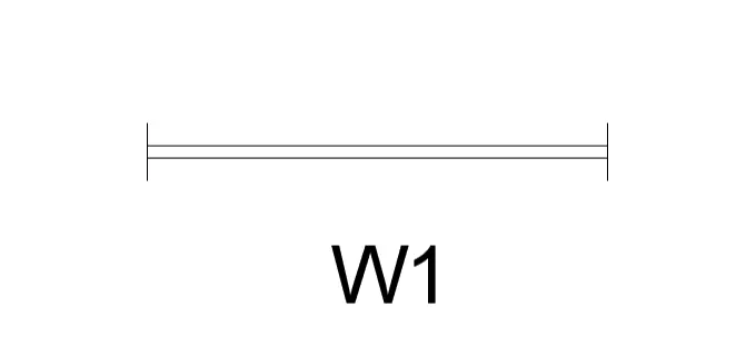
W1 : 6' X 4'
W2 : 4' X 4'
V : 2' X 4'
- For drawing the windows,using the line command by typing L in the command line and then press Enter.
- Window W1 is created with a width of 6'.
- Press Esc to cancel the line command.
- Using the line tool by typing L in the command line and then press Enter.
- Window W2 is created with a width of 4'.
- Press Esc to cancel the line command.
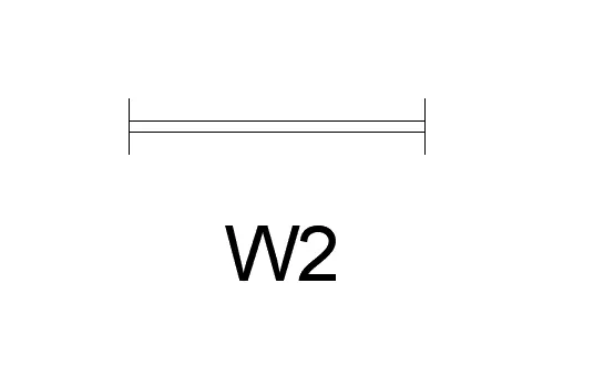
- Using the line tool by typing L in the command line and then press Enter.
- Ventilator V is created with a width of 2'.
- Press Esc to cancel the line command.
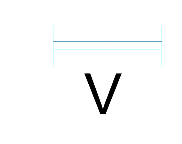
- Now convert the doors,windows and the ventilators in the blocks.
- Type B in the command line and then press Enter.
- Specify a pick point and select the objects individually and assign the names to the blocks.
- Type I in the command line and then press Enter.
- Insert the doors, windows and ventilators where required with suitable rotation.
COLUMN:
- To draw the column, select the column layer from the layer property.
- Select the column layer as the default layer.
- Column can be draw by using the rectangle tool.
- And to invoke the rectangle tool type REC in the command line and then press Enter.
- Specify the first point anywhere in the drawing and then type d and enter.
- Now specify the length and width of the rectangle.
- Draw the column of length and width 1' X 9".
- Press Esc to cancle the rectangle command.
- Now use the copy command we can copy the column to their respective positions.
- Type CO in the command line and then press Enter.
- Press Esc to cancel the copy command.
- Using hatch command we can hatch the column.
- Type H in the command line and then press Enter.
- Select AR-CONC pattern and select the pick point inside the colum.
- Press Esc to cancel the hatch command.
FURNITURE:
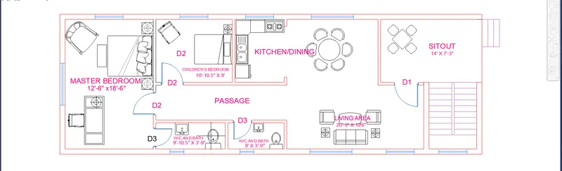
- To create the furniture, select the furniture layer from the layer properties.
- Set the furniture layer as the default layer.
- Type ADC in the command line and then press Enter.
- Select the desired furniture and appliances and copy them to our drawing sheet.
- And scale them according to the drawing scale.
- Press Esc.
CHAJJA:
- To draw the chajja,select the chajja layer from the layer property.
- And set the chajja layer as the default layer.
- By using the line tool we can draw the chajja. Just type L in the command line and then press Enter.
- Draw the chajjas using the line.
- Press Esc.
- Now go to the properties and change the line type to the dashed.
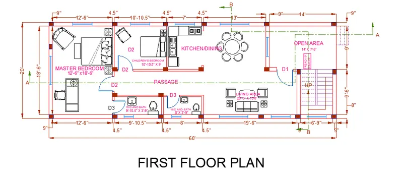
SECTION LINE AA :
- To draw the section line AA use line command.
- Type L in the command line and then press Enter.
- Now draw the section line AA and section line BB within the drawing.
- Press Esc to cancel the line command.
- Now go to the properties and change the linetype to the long dash short dash.
DIMENSION AND TEXT:
- To enter the text,select the dimension and text layer from the layer property.
- And set the dimension and text layer as the default layer.
- Type D in the command line and then press Enter.
- Click in the modify button under the text option change the text height to 2'.
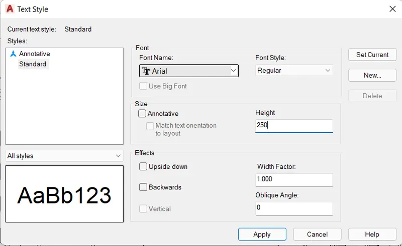
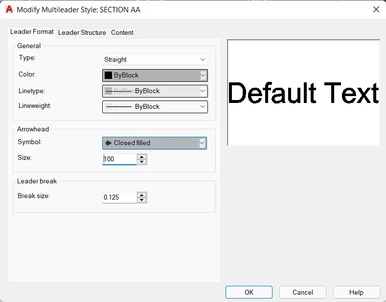
- Click OK and then click on the set current and then close the dialog box.
- Type DIMLIN in the command line and then press Enter.
- And give the dimensions using dimlinear option.
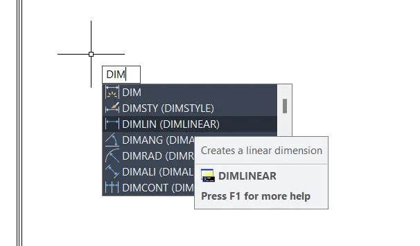
- After giving the dimensions to the plan press Esc to cancel the DIMLIN command.
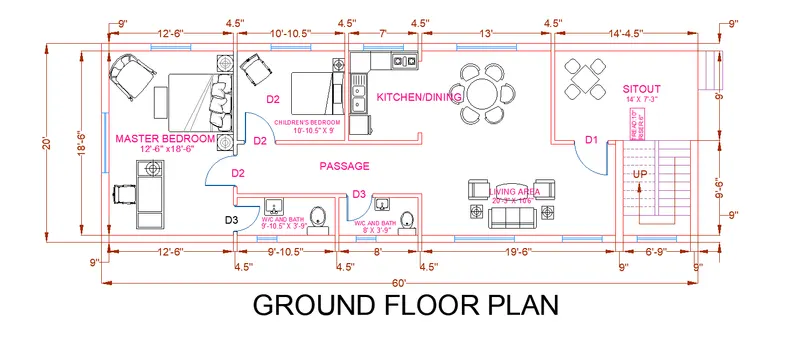
- Now type MTEXT in the command line and then press Enter.
- Specify the start point of the text.
- Scale the text to the desired size.
- Enter the text at the required positions.
- Press Esc to cancel the MTEXT command.
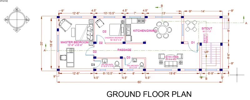
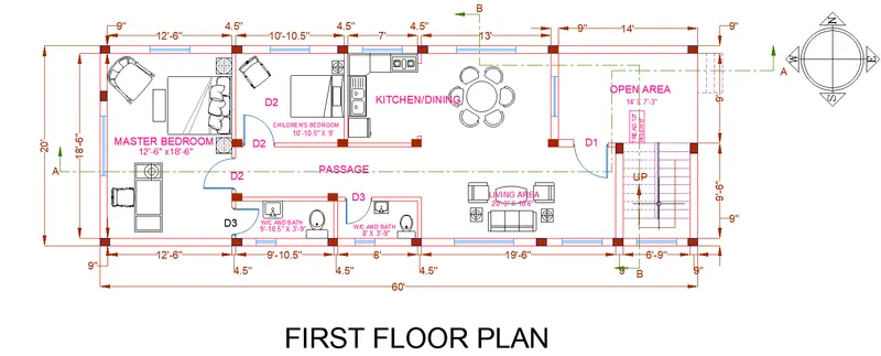
B) ELEVATION:
- To draw the elevation of the given plan use the construction line command to create the elevation.
- To invoke the construction line command just type XL in the command line and then press enter.
- Type V in the command line for the vertical lines.
- Draw the projection lines from the plan created.
- Press Esc to cancel the XL command.
- Again use the XL command. Just type XL in the command line and then press Enter.
- Press H in the command line for the horizontal lines.
- Draw a horizontal line at a suitable distance.
- Press Esc to cancel the XL command.
- Now use the trim tool.
- And to invoke the trim tool we need to type TR in the command line and then press Enter.
- Now trim the all unwanted lines using trim command.
- Press Esc to cancel the trim command.
- Use offset command by typing OFFSET in the command line and then press Enter.
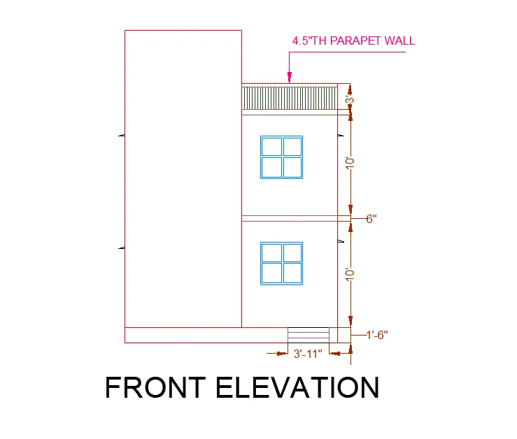
- Now offset the horizontal line to a offset distance of 1'-6" i.e the plinth height, now again using the offset give a distance of 10' in the upward direction and this is the floor height and again give the offset of distance 8' in the upward direction i.e, the terrace height.
- And the vertical xlines are offseted according to the room dimensions and the wall thickness.
- Press Esc to cancel the offset command.
- Use trim tool to trim the all unwanted lines.
- Type TR in the command line and then press Enter.
- Press the Esc to cancel the trim command.
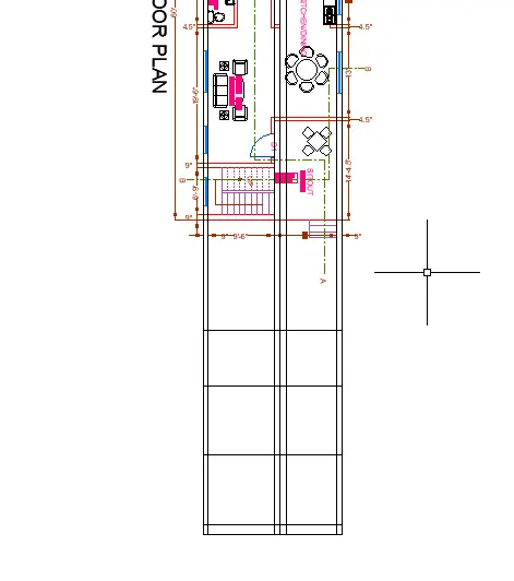
WINDOWS AND DOORS:
- To create the windows in the elevation. using the offset command create the offset for the windows.
- The height of the window is 4'.
- Take the offset distance as 4'.
- Press Esc to cancel the offset command.
- Using the trim command, trim all the unwanted lines.
- Press Esc to cancel the trim command.
- Draw the windows.
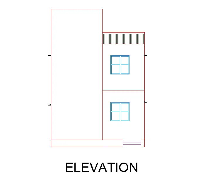
DIMENSION AND MTEXT:
- To enter the text,select the dimension and text layer from the layer property.
- And set the dimension and text layer as the default layer.
- Type D in the command line and then press Enter.
- Click in the modify button under the text option change the text height to 2'.
- Click OK and then click on the set current and then close the dialog box.
- Type DIMLIN in the command line and then press Enter.
- And give the dimensions using dimlinear option.
- After giving the dimensions to the plan press Esc to cancel the DIMLIN command.
- Now type MTEXT in the command line and then press Enter.
- Specify the start point of the text.
- Scale the text to the desired size.
- Enter the text at the required positions.
- Press Esc to cancel the MTEXT command.
C) SECTION AA:
- To draw the section AA of the given plan use the construction line command to create the section AA.
- To invoke the construction line command just type XL in the command line and then press enter.
- Type V in the command line for the vertical lines.
- Draw the projection lines from the plan created.
- Press Esc to cancel the XL command.
- Again use the XL command. Just type XL in the command line and then press Enter.
- Press H in the command line for the horizontal lines.
- Draw a horizontal line at a suitable distance.
- Press Esc to cancel the XL command.
- Now use the trim tool.
- And to invoke the trim tool we need to type TR in the command line and then press Enter.
- Now trim the all unwanted lines using trim command.
- Press Esc to cancel the trim command.
- Use offset command by typing OFFSET in the command line and then press Enter.
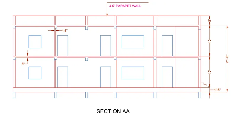
- The horizontal xlines are offseted according to the storey height.
- Press Esc to cancel the offset command.
- Use trim tool to trim the all unwanted lines.
- Type TR in the command line and then press Enter.
- Press the Esc to cancel the trim command.
WINDOWS AND DOORS:
- To create the windows and doors in the SectionAA by using the offset command create the offset for the windows and doors.
- Create the offsets according to the assumed data for the doors and the windows.
- The height of the door is 6'-8' and the height of the window is 4'.
- Press Esc to cancel the offset command.
- Using the trim command, trim all the unwanted lines.
- Press Esc to cancel the trim command.
- Assign the different objects to the different layers.
DIMENSION AND MTEXT:
- To enter the text,select the dimension and text layer from the layer property.
- And set the dimension and text layer as the default layer.
- Type D in the command line and then press Enter.
- Click in the modify button under the text option change the text height to 2'.
- Click OK and then click on the set current and then close the dialog box.
- Type DIMLIN in the command line and then press Enter.
- And give the dimensions using dimlinear option.
- After giving the dimensions to the plan press Esc to cancle the DIMLIN command.
- Now type MTEXT in the command line and then press Enter.
- Specify the start point of the text.
- Scale the text to the desired size.
- Enter the text at the required positions.
- Press Esc to cancel the MTEXT command.
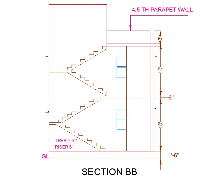
D) SECTION BB:
- To draw the section BB of the given plan use the construction line command to create the section AA.
- To invoke the construction line command just type XL in the command line and then press enter.
- Type V in the command line for the vertical lines.
- Draw the projection lines from the plan created.
- Press Esc to cancel the XL command.
- Again use the XL command. Just type XL in the command line and then press Enter.
- Press H in the command line for the horizontal lines.
- Draw a horizontal line at a suitable distance.
- Press Esc to cancel the XL command.
- Now use the trim tool.
- And to invoke the trim tool we need to type TR in the command line and then press Enter.
- Now trim the all unwanted lines using trim command.
- Press Esc to cancel the trim command.
- Use offset command by typing OFFSET in the command line and then press Enter.
- The horizontal xlines are offseted according to the storey height.
- Press Esc to cancel the offset command.
- Use trim tool to trim the all unwanted lines.
- Type TR in the command line and then press Enter.
- Press the Esc to cancel the trim command.
STAIRS:
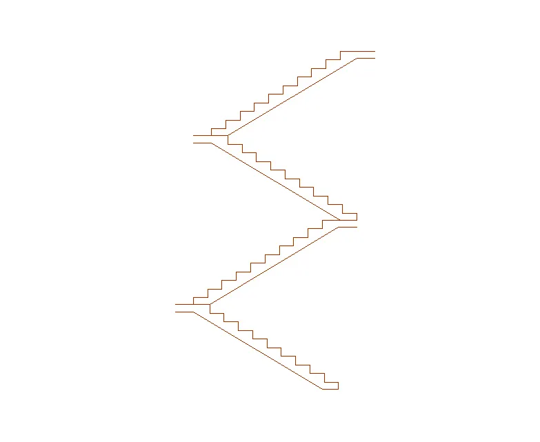
- Select the line command to draw the stairs.
- Type L or line in the command line and then press Enter.
- Draw stairs using line command. The dimensions are riser is of 6" and tread is of 10".
- Press Esc to cancel the line command.
- Using the copy command we can copy this to create the flight of stairs.
- Now press Esc to cancel the copy command.
- Now assign a layer to this stair fight from layer properties.
MTEXT AND ANNOTATIONS:
- To enter the text,select the dimension and text layer from the layer property.
- And set the dimension and text layer as the default layer.
- Type D in the command line and then press Enter.
- Click in the modify button under the text option change the text height to 2'.
- Click OK and then click on the set current and then close the dialog box.
- Type DIMLIN in the command line and then press Enter.
- And give the dimensions using dimlinear option.
- After giving the dimensions to the plan press Esc to cancel the DIMLIN command.
- Now type MTEXT in the command line and then press Enter.
- Specify the start point of the text.
- Scale the text to the desired size.
- Enter the text at the required positions.
- Press Esc to cancel the MTEXT command.
RESULT:
2) STRUCTURAL DRAWINGS:
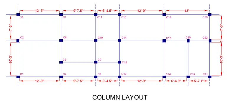
A) COLUMN LAYOUT:
- First of all turn OFF all the layers except the column layer.
- Now use the copy command to copy all the column of the plan to a different place.
- Type CO or copy in the command line and then press Enter.
- Now press Esc and cancel the copy command.
- Now turn ON all the layers.
- To invoke the construction line command just type XL in the command line and then press enter.
- Type V in the command line for the vertical lines.
- Draw lines throught the mid-point of the columns.
- Press Esc to cancel the XL command.
- Again use the XL command. Just type XL in the command line and then press Enter.
- Press H in the command line for the horizontal lines.
- Draw lines throught the mid-point of the columns.
- Press Esc to cancel the XL command.
- Use trim tool to trim the all unwanted lines.
- Type TR in the command line and then press Enter.
- Press the Esc to cancel the trim command.
- Select the lines and right click,go to the properties and change its linetype to ACAD_ISO02W100.
- To enter the text,select the dimension and text layer from the layer property.
- And set the dimension and text layer as the default layer.
- Type D in the command line and then press Enter.
- Click in the modify button under the text option change the text height to 2'.
- Click OK and then click on the set current and then close the dialog box.
- Type DIMLIN in the command line and then press Enter.
- And give the dimensions using dimlinear option.
- After giving the dimensions to the plan press Esc to cancel the DIMLIN command.
- Now type MTEXT in the command line and then press Enter.
- Specify the start point of the text.
- Scale the text to the desired size.
- Enter the text at the required positions.
- Press Esc to cancel the MTEXT command.
B) BEAM LAYOUT:
- Now use the copy command to copy the column layout of the plan to a different place.
- Type CO or copy in the command line and then press Enter.
- Press Esc and then press Enter.
- Use offset command by typing OFFSET in the command line and then press Enter.
- Specify offset distance as 4.5" and create offset for the beam of width 9".
- Press Esc and then press Enter.
- Again use offset command by typing OFFSET in the command line and then press Enter.
- Specify offset distance as 6" and create offset for the beam of width 1'.
- Use trim tool to trim the all unwanted lines.
- Type TR in the command line and then press Enter.
- Press the Esc to cancel the trim command.

- To enter the text,select the dimension and text layer from the layer property.
- And set the dimension and text layer as the default layer.
- Type D in the command line and then press Enter.
- Click in the modify button under the text option change the text height to 2'.
- Click OK and then click on the set current and then close the dialog box.
- Type DIMLIN in the command line and then press Enter.
- And give the dimensions using dimlinear option.
- After giving the dimensions to the plan press Esc to cancel the DIMLIN command.
- Now type MTEXT in the command line and then press Enter.
- Specify the start point of the text.
- Scale the text to the desired size.
- Enter the text at the required positions.
- Press Esc to cancel the MTEXT command.
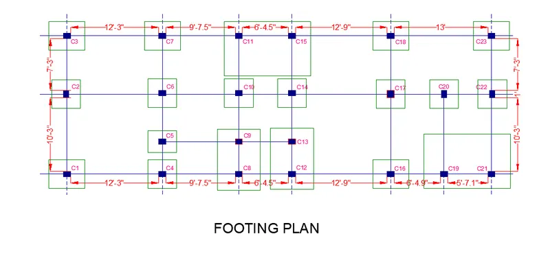
C) FOOTING PLAN:
- Use the copy command to copy the column layout of the plan to a different place.
- Type CO or copy in the command line and then press Enter.
- Press Esc and then press Enter.
- Select the footing layer from the layer properties.
- Now type REC or rectangle in the command line and then press Enter.
- Draw a rectangle of dimensions 4' X 5'.
- Now using the copy command, copy this rectangle specify the base point and copy it in the columns C1,C3,C7,C16,C18 and C23.
- Press Esc to cancel the rectangle command.
- Now type REC or rectangle in the command line and then press Enter.
- Draw a rectangle of dimensions 4' X 4'.
- Now using the copy command, copy this rectangle specify the base point and copy it in the columns C2,C6,C10,C14,C17,C20 and C22.
- Press Esc to cancel the rectangle command.
- Now again type REC or rectangle in the command line and then press Enter.
- Draw a rectangle of dimensions 4' X 3'.
- Now using the copy command, copy this rectangle specify the base point and copy it in the columns C5.
- Press Esc to cancel the rectangle command.
- Now type REC or rectangle in the command line and then press Enter.
- Draw a rectangle of dimensions 6' X 8'6".
- Now using the copy command, copy this rectangle specify the base point and copy it in the columns C8,C9,C12 and C13.
- Press Esc to cancel the rectangle command.
- Now type REC or rectangle in the command line and then press Enter.
- Draw a rectangle of dimensions 12' X 7'7".
- Now using the copy command, copy this rectangle specify the base point and copy it in the columns C11,C15,C19 and C21.
- Press Esc to cancel the rectangle command.
RESULT: