Project 1 _Creating an Architectural plan for the provided plot size and develop relevant basic structural drawings
PROJECT 1 :
Creating an archietectural plan for provided plot size and develop relevant basic structural drawings.
AIM :
Design and Draft a layout of a residential building with the following details:
a. Plot Size: 60’x20’(18.3m x6m)
b. Orientation- Facing East
ARCHIETECTURAL DRAWINGS INCLUDE THE FOLLOWING :
- Site plan
- ground floor plan
- first floor plan
- section
- elevation
STRUCTURAL DRAWING INCLUDES :
- Column layout
- beam layout
- footing layout
INTRODUCTION :
A structural drawing, a type of engineering drawing, is a plan or set of plans and details for how a building or other structure will be built. Structural drawings are generally prepared by registered professional engineers, and based on information provided by architectural drawings.
A sketch, diagram, plan, or schematic used to design, construct, and document buildings and other structures.
COMMANDS USED :
| ARC | Create an arc |
| AREA | Find the area of closed or open shapes in a drawing |
| AR/ ARRAY | Make a rectangle, polar, or path array |
| B/ BLOCK | Create a block |
| BCOUNT | Count the number of blocks in your drawing |
| C/ CIRCLE | Create a circle |
| DS/ DDOSNAP | Open the Drafting Settings window |
|
ELLIPSE |
Make an ellipse with the major and minor axis |
| GROUP | Group multiple objects into a single unit |
| HIDEOBJECTS | Hide selected objects in a drawing |
| HIGHLIGHT | Highlight a selected object in a drawing |
| ISOLATE | Hide all objects in a drawing except the one you have selected |
| L/ LINE | Create a simple line |
| MI/ MIRROR | Produce a mirror copy of an object |
| MLINE | Create multiple parallel lines |
| PL/ PLINE | Make a polyline |
| PO/ POINT | Create a single point within a drawing |
| POL/ POLYGON | Produce a polygon (you select the number of sides, from 3 to 1024) |
| QSELECT | Make a particular selection from your drawing according to applied filters, i.e – select all lines below a particular length |
| REC/ RECTANGLE | Create a rectangle |
| SKETCH | Draw a freehand sketch within a piece of work |
| SPLINE | Create a smooth curve that passes through or near specified points |
| XLINE/XL | Create a line of infinite length |
| ADCENTER/ADC | Insert or manage content such as blocks, hatch patterns, and xrefs |
| ALIGN/AL | Align objects with other objects in 2D and 3D |
| BASE | Alter the base point of a drawing without changing its origin |
| BPARAMETER/ PARAM | Add a parameter with grips to a dynamic block definition |
| BREAK | Create a break (or gaps) in objects at one or two points |
| BSAVE | Save the current block definition |
| BURST | Explode a block but retain its attribute settings and layer definition |
| CHA/ CHAMFER | Add slanted edges to sharp corners of objects |
| COPYBASE | Copy an object according to a base point |
| DIVIDE | Divide objects into multiple equal parts |
| F/ FILLET | Add rounded corners to the sharp edges of objects |
| LA/ LAYERS | Open the Layer Properties Manage Palette (which allows you to tweak the settings for layers) |
| MA/ MATCHPROPERTIES | Copy the properties of one object onto another |
| MOCORO | Move, copy, rotate and scale an object in one command |
| OVERKILL | Remove overlapping or unnecessary objects from your work |
| PURGE | Remove unused objects from a drawing |
| SC/ SCALE | Change the scale of an object |
| SCALETEXT | Change the scale of text |
| TEXTFIT | Alter the size of a piece of text so that it fits into the required space |
| TEXTTOFRONT | Bring annotations to the front |
| TORIENT | Change the orientation of the text |
| TR/ TRIM | Trim a shape or line |
| UNITS | Alter the unit settings of your drawing |
| X/ EXPLODE | Break up an object into its individual components—i.e., a polyline into simple lines |
| XBIND/ XB | Bind the definitions of named objects in an xref to the current drawing |
| AUDIT | Check and remove errors from your work |
| BEDIT/ BE | Open the block definition in the Block Editor |
| BCLOSE/ BC | Close the Block Editor |
| CLOSEALL | Close all of the open windows in AutoCAD |
| CLOSEALLOTHER | Close all open windows except for the one you are currently working on |
| CO/ COPY | Copy objects or text |
| COLOR/ COL | Set the color for new objects |
| DI/ DISTANCE | Find the distance between two points in a drawing |
| ERASE/E | Remove or erase objects from a drawing |
| ETRANSMIT/ ZIP | Create a Self-Extracting or Zipped file |
| I/ INSERT | Insert (existing block or drawing as a block) |
| LIST | Access the properties of the different objects within a drawing |
| MATLIB | Import or export materials from a library |
| MULTIPLE | Repeat any command without having to press Enter each time (Press Esc key to cancel) |
PROCEDURE :
- Type UN and press Enter
- under drawing units select metric
- set the limit
- type z enter A enter
SITE LAYOUT:
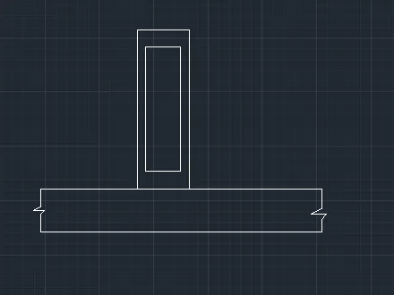
- All dimensions are in mm
- use rec command , to craete @ dimension 14300, length and 6000 width
- use xplode command to un join the line command
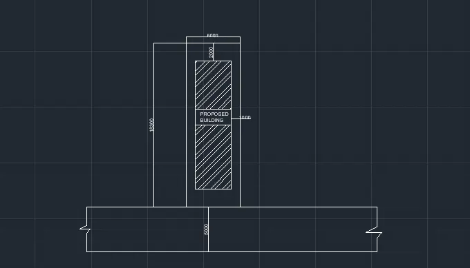
- and use of offset command , offset distance 2000 @ bredth side and offset 1000 @ length side of rec
- now hatch the centre layer using hatch command
- craete a road @ opposite of width side given below
- offste @ a distance of 5000
- both the ends are used as break line given below
- now give the dimensions, and text wherever required.
STEP 2 :
GROUND FLOOR PLAN :
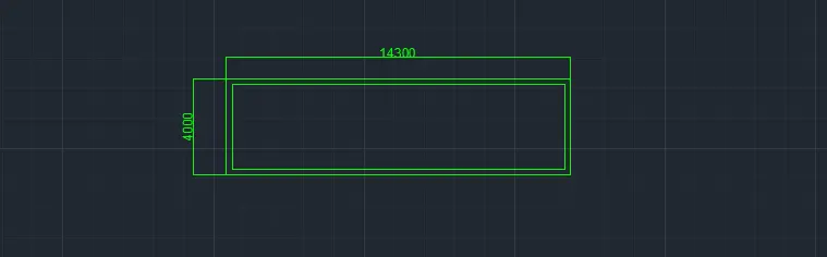
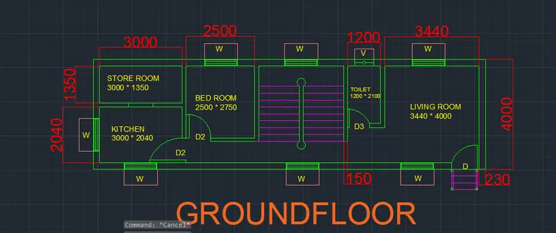
The size of proposed building is 4000*14300 mm
1. External walls .
- dimensions are in mm
- @ the menu bar click rectangle
- with the dimensions, length as 14300
- breadth as 4000
- offset @ a distance 230 mm , trim the unnecessary lines.
- tap the dimensions as shown below.
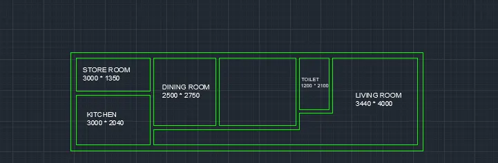
2. Internal walls .
- dimensions are in mm
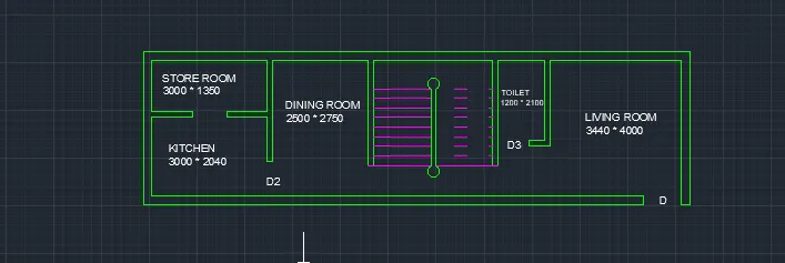
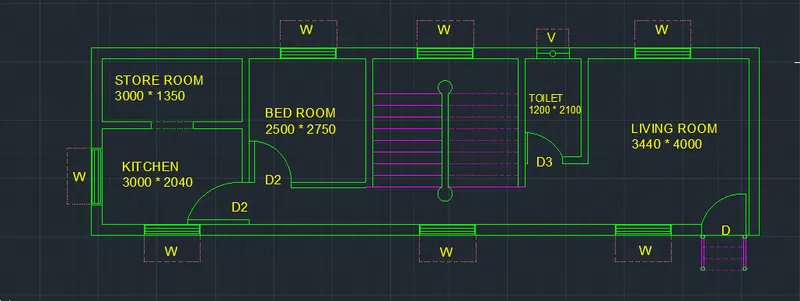
- to craete a store room , O enter> 3000 of short length and 1350 of long length and trim the unwanted lines.
- to create a kitchen, O enter> 3000 of short length and 2040 of long length and trim unwanted lines as shown below
- as same as procedure , create a dining room, toilet, and living room given below
3. Stair case .
- create a staire case , as showm below
- rise 173.45
- tread 250
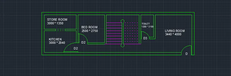
4. Doors .
D = 1000 * 2100
D1 = 900 *2100
D2 = 800 * 2100
- creation of doors using arc command and line command as shown below
- and specify text wherever required.
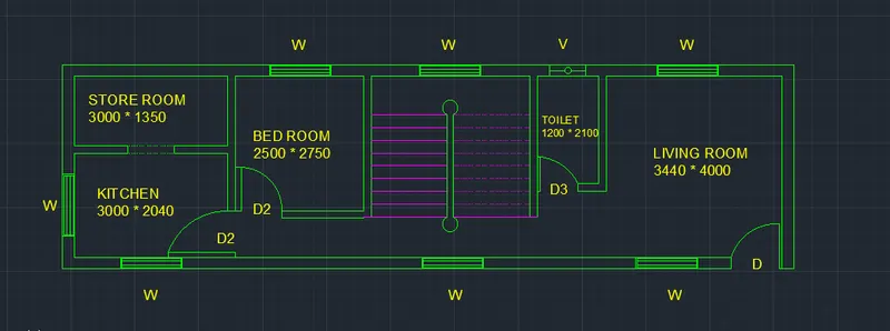
5. Windows.
W = 12OO
V = 700
- creation of window and ventilator using rec command or line command
- place it wherever required in the floor plan
- to intimate , create a text wherever required.
- using layers properties , to create a different layer for our convential use .
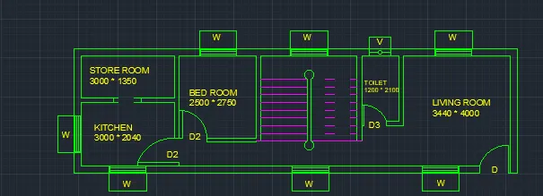
- with line type #center> create a sunshade wherever required.
- convert a different layer as shown below.
6. Dimensions.
- creation of window and ventilator using rec command or line command
- place it wherever required in the floor plan
- to intimate , create a text wherever required.
 \
\
7. Text.
- create a single text, wherever required,
- using layer management create a layer for text as shown below
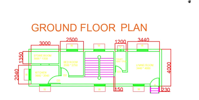
8. Layers.
- all the are placed as per plan shown below using layer properties in menu bar.
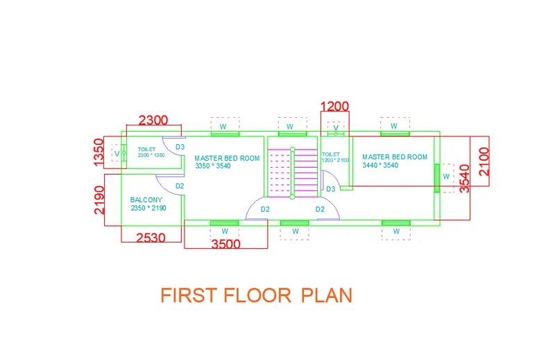
FIRST FLOOR PLAN :
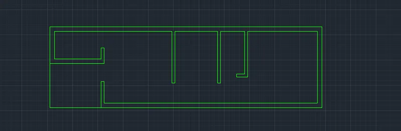
1. EXTERNAL WALLS.
- dimensions are in mm
- @ the menu bar click rectangle
- with the dimensions, length as 14300
- breadth as 4000
- offset @ a distance 230 mm , trim the unnecessary lines.
- tap the dimensions as shown below.
2. INETERNAL WALLS.
- dimensions are in mm
- to craete a store room , O enter> 3000 of short length and 1350 of long length and trim the unwanted lines.
- to create a kitchen, O enter> 3000 of short length and 2040 of long length and trim unwanted lines as shown below
- as same as procedure , create a dining room, toilet, and living room given below
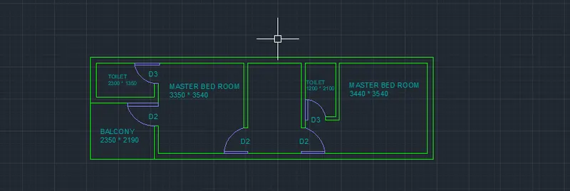
3. DOORS.
D = 1000 * 2100
D1 = 900 *2100
D2 = 800 * 2100
- creation of doors using arc command and line command as shown below
- and specify text wherever required.
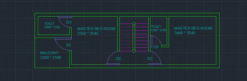
3. STAIR CASE :
create a staire case , as showm below
- rise 173.45
- tread 250
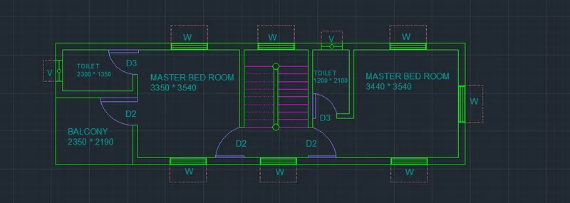
5. WINDOWS .
VENTILATORS
W = 12OO
V = 700
- creation of window and ventilator using rec command or line command
- place it wherever required in the floor plan
- to intimate , create a text wherever required.
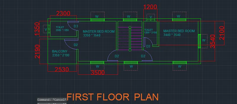
6. DIMENSIONS.
- creation of window and ventilator using rec command or line command
- place it wherever required in the floor plan
- to intimate , create a text wherever required.
TEXT.
- create a single text, wherever required,
- using layer management create a layer for text as shown below
LAYERS.
- all the are placed as per plan shown below using layer properties in menu bar.
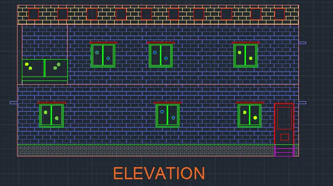
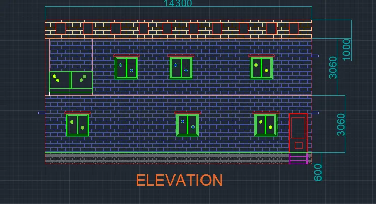
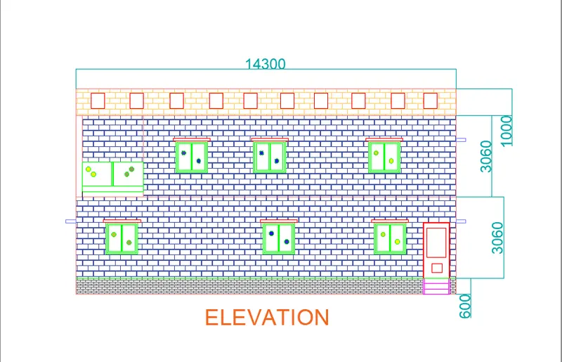
ELEVATION :
- using xl command , draw xl line >vertical, wherever required to draw the elevation of the given plan
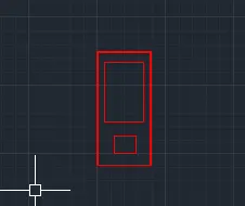
- DOOR.
- Create a door using rec command and line command
- make a door as required dimensions which is convincible as shown.
- using layer management craete a layer for our use.
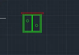
WINDOW .
- create a window using rec command and line command
- make a window as required dimension mentioned above
- using layer management craete a layer for our use.
- place the door and windows wherever required.
- using hatch command place the hatch wherever required.
- @ scale >50
With Dimensions :
- place the dimensions wherever required.
- using layer management create a layer , as shown below and place it
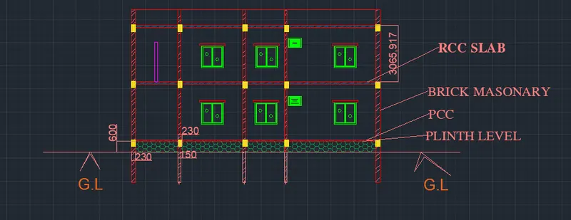
SECTION A-A
- draw the section line A-A as shown below
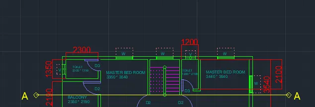
- create a section using the command , line > rectangle > trim > extend > hatch > layer mange ment
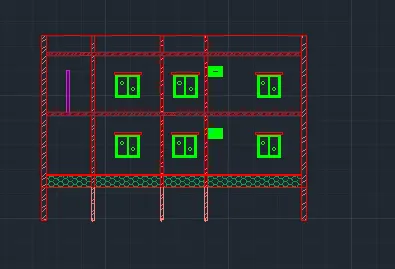
BEAM:
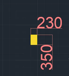
- craete a beam using rec command
- length<350mm
- breadth<230mm
- and hatch the beam using hatch command
- place the baem whrever required
- using copy command and move command
- place the dimensoions wherever required
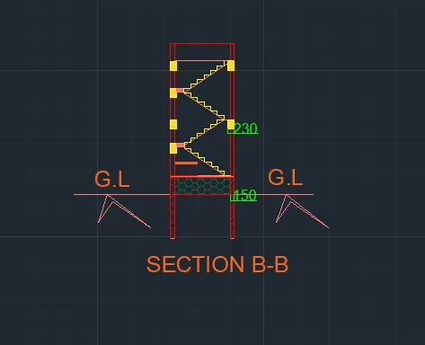
SECTION B--B
BEAM
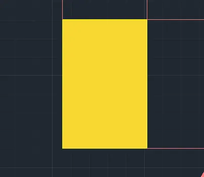
- craete a beam using rec command
- length<350mm
- breadth<230mm
- and hatch the beam using hatch command
- create a section using the command , line > rectangle > trim > extend > hatch > layer mange ment
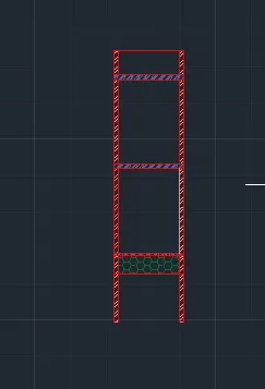
- place the baem whrever required
- using copy command and move command
- place the dimensoions wherever required
- draw a staircase
- with rise 170
- tread 250
- using hatch command , hatch the layers .
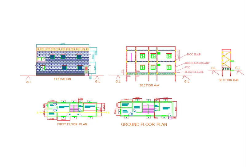
Archietectural Drawing is ready :
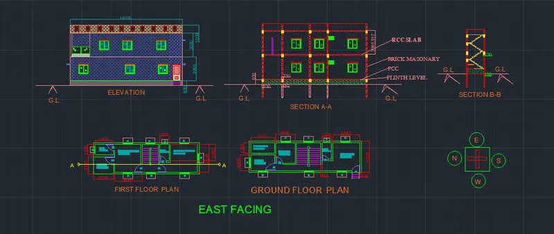
STRUCTURAL DARWINGS.
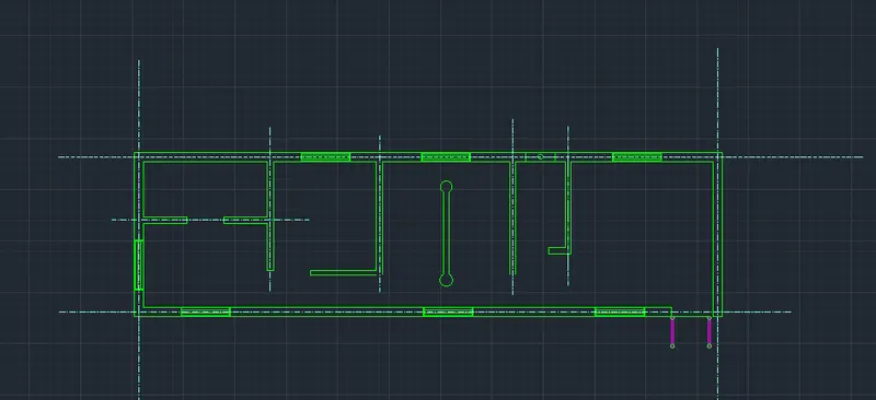
COLUMN LAYOUT:
- by turn off the all layers ,
- switch on only the external and inner wall layer, to create a column layout
- using line command create a column as shown below
- using line type, click>load>select center>global scale 70000>ok
- copy the column layout and paste it
- using rec command,
- length>230 mm
- breadth>230 mm
- place the column wherever required and hatch it using hatch command
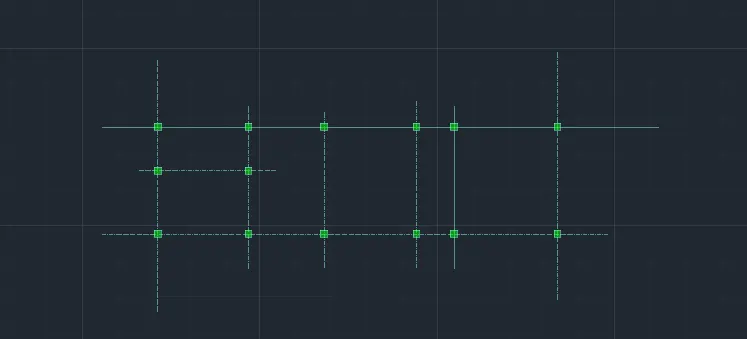
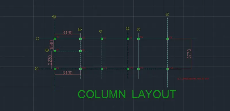
- name the column as shown below using single text
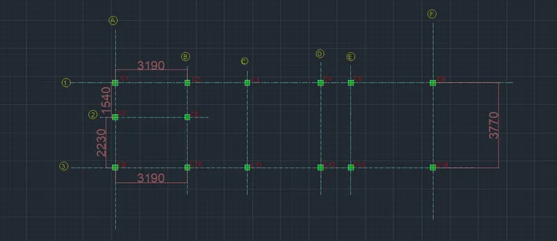
- draw the dimensions wherever required. using layer mangement, create a different layers and place it for our use.
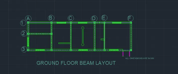
GROUND FLOOR BEAM LAYOUT :
- by turn off the all layers ,
- switch on only the external and inner wall layer, to create a column layout
- using line command create a column as shown below
- using line type, click>load>select center>global scale 70000>ok
- copy the column layout and paste it
- using rec command,
- length>230 mm
- breadth>230 mm
- place the column wherever required and hatch it using hatch command
- name the column as shown below using single text
- draw the dimensions wherever required. using layer mangement, create a different layers and place it for our use.
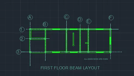
FIRST FLOOR BEAM LAYOUT :
- by turn off the all layers ,
- switch on only the external and inner wall layer, to create a column layout
- using line command create a beam as shown below
- using line type, click>load>select center>global scale 70000>ok
- copy the column layout and paste it
- using rec command,
- place the beam, wherever required and hatch it using hatch command
- name the beam as shown below using single text
- draw the dimensions wherever required. using layer mangement, create a different layers and place it for our use.
FOOTING LAYOUT :
- by turn off the all layers ,
- switch on only the external and inner wall layer, to create a column layout
- using line command create a column as shown below
- using line type, click>load>select center>global scale 70000>ok
- copy the column layout and paste it
- using rec command,
- length>500 mm
- breadth>500 mm
- place the footing wherever required and hatch it using hatch command
- name the footing as shown below using single text
- draw the dimensions wherever required. using layer mangement, create a different layers and place it for our use.
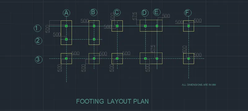
THE STRUCTURAL DRAWING IS READY,
RESULT :
ARCHIETECTURAL DRAWING .
1. GROUND FLOOR PLAN .
2. FIRST FLOOR PLAN .
3. ELEVATION .
4. SECTION A-A
5. SECTION B-B
* STRUCTURAL DRAWING :
1. COLUMN LAYOUT PLAN :
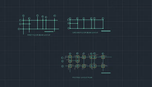
2. GROUND / FIRST FLOOR BEAM LAYOUT PLAN.
3. FOOTING LAYOUT PLAN :