Project 1 _Creating an Architectural plan for the provided plot size and develop relevant basic structural drawings
AIM:
To draw the Residential Building in the plot size of 18.3 m x 6 m facing East direction with the following.
Architectural drawing”
- Site Plan
- Ground Floor Plan
- First Floor Plan
- Elevation
- Section
Structural drawing
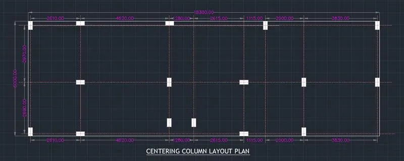
- Column Layout
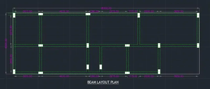
- Beam layout
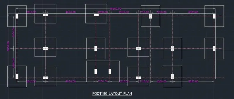
- Footing layout
Dimensions:
- External wall = 230 mm
- Internal wall = 150 mm
- Staircase = 250mm tread, 175mm rise.
Commands used:
Polyline/Line, Multi-text/Text, Offset, Extend, Fillet, Mirror, Trim, Move, Block, Block edit, Rotate, Hatch, Annotate.
INTRODUCTION:
The Residential building to be drawn with plot dimensions 18.3 x 6 Sq.m Area. The G+1 floor is designed with staircase outside the house. The plot is East facing. The building is esigned with following rooms.
- Ground floor living room
- Kitchen (Open) with Dining room
- Pooja room
- Master Bedroom with attach Toilet
- Bedroom with store room & backside Verandah
- Common Toilet
- First floor living room
- Kitchen (Open) with Dining room
- Pooja room
- Master Bedroom with attach Toilet
- Bedroom with store room & backside Verandah
- Common Toilet
Building is designed with Main door at East facing & Main gate also East facing.
Dimensions of the components of house are as follows.
Walls:
- Thickness of main walls is taken as 230mm
- Internal wall thickness is taken as 150mm.
Columns and Beams:
- All the columns are of size 450x230mm
- All the beams are of size 200x200mm
Doors:
- Dimension of Entrance door 1000mm
- Dimension of Bedroom door 900mm
- Dimension of toilet door 600mm
Windows:
- Windows to the side of main door are taken as 1200x1200mm
- Windows in master bedroom is taken as 1500x1200mm
- Windows in bedroom is taken as 1000x1200mm
Staircase:
- Staircase consists of 18 steps from Ground floor to First floor & 18 steps from first floor to Terrace
- Thread = 250mm
- Riser = 175mm
PROCEDURE
Step-1: New Sheet-Units-Decimal-precision 0.0 meter & OK.
Step-2: Analyze the plot area & plan accordingly proposed building should be in the area, the area is 18300 x 6000 mm.
Type XL in command line to draft the infinite lines where ever required according to assumed plan.
Offset the lines to 230mm exterior & 150mm interior walls.
Entrance of the plan is at east direction.
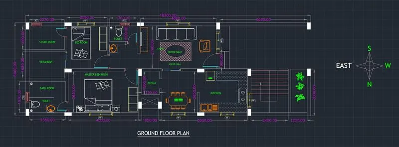
Step-3: First using command: REC Rectangle > 4860 x 2740 to create Living Room
Command: Rectangle > 5500 x 2650 to create Kitchen / Dining room.
Command: Rectangle > 1500 x 1130 to create pooja room.
Command: Rectangle > 4500 x 2650 to create Master bedroom.
Command: Rectangle > 2590 x 2740 to create bedroom.
Command: Rectangle > 2350 x 1970 to create Toilet & Bathroom
Command: Rectangle > 2270 x 1500 to create storeroom.
Command: Rectangle > 2270 x 1690 to create Verandah.
Command: Rectangle > 1760 x 1000 to create Toilet.
Step-4: Command: REC Rectangle > To create Columns 450x230mm locate the column location as shown in given sketch, & specify the column layers.
Step-5: Command: PL Polyline, using this to create staircase width 1200mm & Thread=250mm & Raise=175mm.
Step-6: Creating layer properties for different layers like walls, doors, windows, text, grid lines, columns etc.
Step-7: Draw the windows and doors with the sizes are shown in below table.
|
Sl.No: |
WINDOWS |
SIZES |
|
1. |
W – Master bedroom |
1500 x 1200 mm |
|
2. |
W - bedroom |
1000 x 1200 mm |
|
3. |
W – Drawing/Kitchen/Living & bedroom |
1200 x1200 mm |
|
4. |
V - Toilet |
500 x 500 mm |
|
Sl.No: |
DOORS |
SIZES |
|
1. |
D- Main door |
1000 x 2100 mm |
|
2. |
D1 - Bedroom |
900 x 2100 mm |
|
3. |
D2 - Toilet |
900 x 2100 mm |
Finally, we indicate the rooms using the Command: T TEXT
Again, we have to provide the dimensions for the given floor plan using the dim linear command.
Step-8: Adding Furniture and Plumbing Equipment.
Design center command is used add home furniture, kitchen equipment and plumbing equipment for the rooms.
Some addition furniture is imported from another file from the inter called CAD Blocks.
Furniture added from from both is.
- Dining table
- Chair-rocking
- Plant
- Bed-queen
- Toilet top
- Kitchen Hob
- Kitchen sink
- Entertainment set
- Sofa for living room
- Plumbing equipment.
Result of Ground Floor Plan.
FIRST FLOOR:
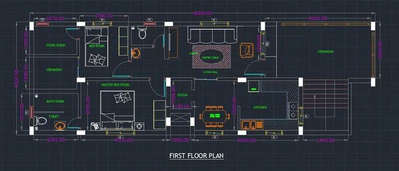
As most of the plan is same for the first floor as well.
Step-1: Command: Rectangle >5600 x 3000 to create First floor Balcony.
Step-2: Command: PL Polyline, using this to create staircase width 1200mm & Thread=250mm & Raise=175mm.
Step-3: Creating layer properties for different layers like walls, doors, windows, text, grid lines, columns etc.
Step-4: Draw the windows and doors with the sizes are shown in below table.
|
Sl.No: |
WINDOWS |
SIZES |
|
1. |
W – Master bedroom |
1500 x 1200 mm |
|
2. |
W - bedroom |
1000 x 1200 mm |
|
3. |
W – Drawing/Kitchen/Living & bedroom |
1200 x1200 mm |
|
4. |
V - Toilet |
500 x 500 mm |
|
Sl.No: |
DOORS |
SIZES |
|
1. |
D- Main door |
1000 x 2100 mm |
|
2. |
D1 - Bedroom |
900 x 2100 mm |
|
3. |
D2 - Toilet |
900 x 2100 mm |
Finally, we indicate the rooms using the Command: T TEXT
Again, we have to provide the dimensions for the given floor plan using the dim linear command.
FRONT & SIDE ELEVATION VIEW:
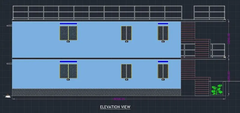
Step-1: For obtaining the proper front elevation view.
- Change the current layer to extension lines
- Create vertical extension line at all the wall edge points
- Draw all the wall with their thick
- Each floor height is taken as 3250mm
- Trim the extra portions.
Step-2: Command: PL Polyline, using this to create staircase width 1200mm & Thread=250mm & Raise=175mm.
Step-3: Creating layer properties for different layers like walls, doors, windows, text, grid lines, columns etc.
Step-4: Draw the windows and doors with the sizes are shown in below table.
|
Sl.No: |
WINDOWS |
SIZES |
|
1. |
W – Master bedroom |
1500 x 1200 mm |
|
2. |
W - bedroom |
1000 x 1200 mm |
|
3. |
W – Drawing/Kitchen/Living & bedroom |
1200 x1200 mm |
|
4. |
V - Toilet |
500 x 500 mm |
STRUCTURAL DRAWING:
- Centering, Column, Beam & Footing Layout
Command: XL infinite line to draw the grid lines.
Type LT to draw the dotted lines if the dotted lines are two small use LTS command to increase the distance b/w the dotted line.
Type REC of dim 230x230mm, taken all measurement in mm,
Footing 750x750 mm for single footing
In case of combined footing 2500x1000mm.
Type command line to draft the beams
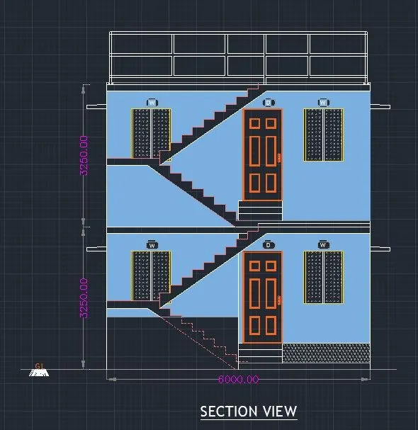
Using dotted line sections, A-A & B-B are created
In the ribbon tab > hatch > to annotations for concrete
Hatching:
The hatching is done for all components of plan & elevation
Elevation patterns are chosen & applied with their respective attributes
Hatch patterns used for respective props.
RESULT:
Residential G+1 floor design consists of plot drawing, plan view, center line drawing, column & beam layouts, elevation view & section views are drawn. The house consists of 4 bedrooms, 2 living rooms, pooja room, kitchen & balcony. Layers are created in the first step & assigned accordingly. After drawing plan view one horizontal section & vertical section lines are drawn named as section 1-1 & section 2-2. Required components and furniture to the house are added using design center command & some other files are added from the cad blocks from browsing.