Project 1 - Controlling a DC motor using PWM and monitoring its Running status
Project 1 - Controlling a DC motor using PWM and monitoring its Running status
Overview of the Project:
Implement a system on the simulator for controlling a DC motor using L293 motor driver, monitor its status and print the running status of motor on the LCD Display.
- from the above question we have to control the DC motor using PWM and monitor its running status ..here we have to use the dc motor and L293 motor driver and one lcd display in that we have to show the running status of motor and which direction it is rotating and we have to increase the speed of motor gradually to a maximum value
- here the main point is we have to control the direction and we have to control the speed and we have to control the on and off and we have to show the running status of the motor in the lcd display
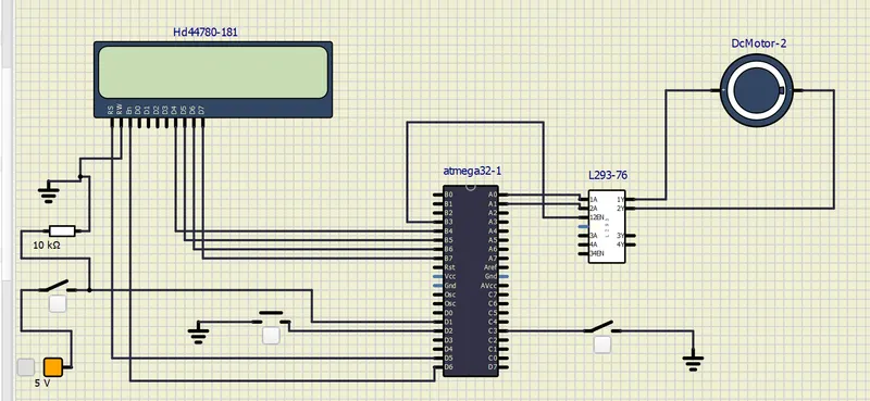
this is thr circuit for the above question here i used one lcd and one atmega 32 micro c0ntroller after one l293 driver and one motor here i given the connections d4 ,d5,d6,d7 lcd ports to atmega 32 micro controller and rs and enable pin given to d5,d6 of micro controller and One push button is connected to the d1 is for direction control and another push button conneccted to the D2 for rapid speed control and another push button is given to the C3 to turn on and off to the motor
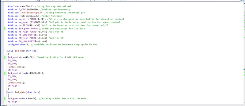

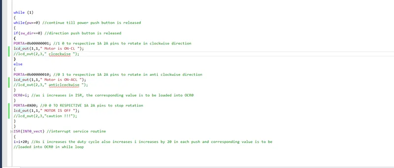
here is the code for the above question in the first i included the avr , intrupt ,delay libraries to access the predefined functions and after i included the 16000000 mhz because the micro control have the capacity of frequency and i declared D1 for the direction control and D2 for the rapid speed control and C3 for controlling the ON and OFF of the dc motor after i declared the D5 for the rs (register select pin)and D6 for the EN enable pin
in the LCD command function first im giving the RS as iow because low means the command mode and after I SET enable pin as LOW after by using the masking technique im just sending the 4 bits of commands by making the enable high with the delay of 1 second
same for the LCD DATA function first im giving rs as high because it means were sending the data after i SET the enable as low by using the masking techniques im just sendiing the 4 bits of data by making the enable pin high with some delay of 1 second
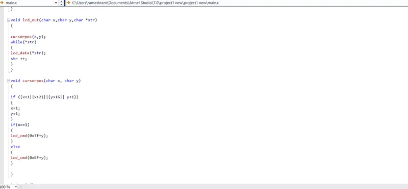
in the LCD OUT function im just passing some arguments in the prototype after im using the while loop in that i gave some condition like until the data is present it goes inside the loop and prints that data and after the data dispaying position increments
in the LCD CURSOR POS function im passing the arguments in the prototype after in the if loop i gave some condtion like the rows should not be less than 1 and should not be greater than 2 like wise the colums should not exceed 16 and should not be less than 1 after i gave some conditon if x==1 it should pass the commands or else it should pass the other commands
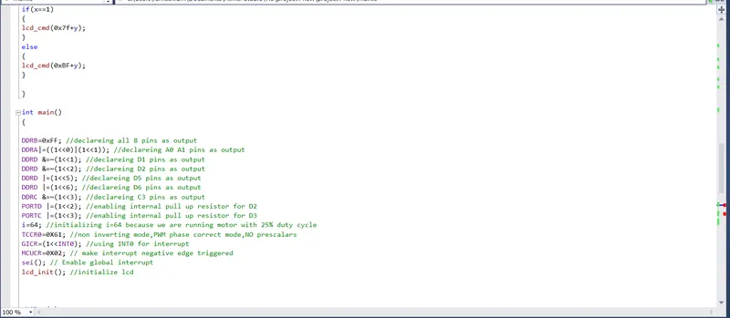
in the MAIN function first im making of all PORT B bits as output so that we can use the entire bits of port b we can some of in it after im making the PORT A 1 and 2 bits as output to the L239 driver by using this we can flip 1 to 0 or 0 to 1 this way it the motor could rotate in clock wise and anti cl0ck wise after im making PORT D1,D2,D5,D6 as outputs and after im making the port c 3 as input after im enabling the port c3 and port d2 pullup registers after im initialising the I value with 64 it nothing but 25% of the duty cycle after im giving the value 0x61 in the output comparator after its nothing but non inverting mode with no prescaler after GICR INT0 value im setting to 1 it enables the INT0 and im using the int0 here after im using MCUCR 0x02 it makes the intrupt to be triggered at negitive edge after im using the sei() it enables the global intrupt after im calling the lcd_init function
in the WHILE loop i gave some condition like until powwer push button is == 0 means its still is in condition so it goes inside the loop when it becomes open it doesnt go inside the loop in the while loop im agin took some if condition like until the direction push button is released it goes inside the loop and the motor should rotate in clock wise direction if the port a 1 is 1 and the port a 2nd pin is 0 or else if port a 1 is 0 and porta 2 pin is 1 it should rotate in anti clockwise direction of the after that if the power push button is not released motor should be in the off condition
after all by pressing the PORTB 2 nd pin connected push button pressing cause to increase the speed by 20% by this formulae i= i+20 here this push button is nothing but an interupt by making the intrupt in program were increasing the motor speed by 20%
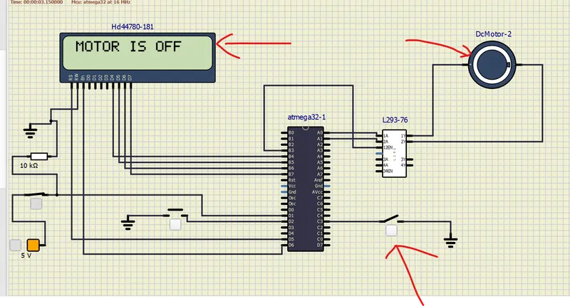
Here we can observe when the port c 3rd pin connected push button is not released motor is in the idle condition and the led displays the motor is in off condition
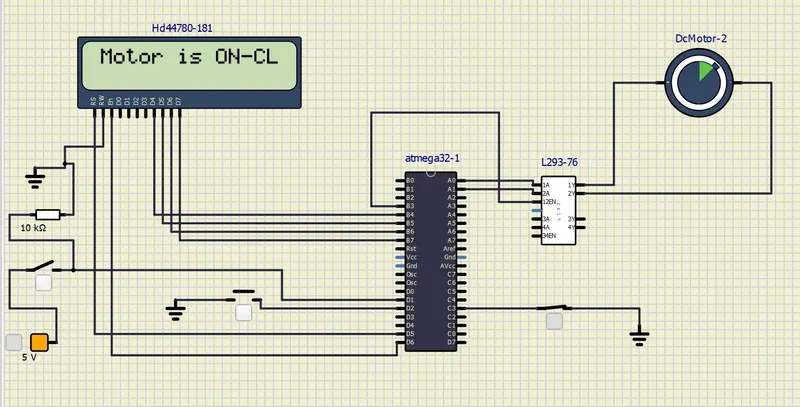
here port c 3rd push button is pressed and we can the motor is rotating in clock wise direction and we can observe this in the lcd that motor is on -cL means motor is rotating in clock wise direction
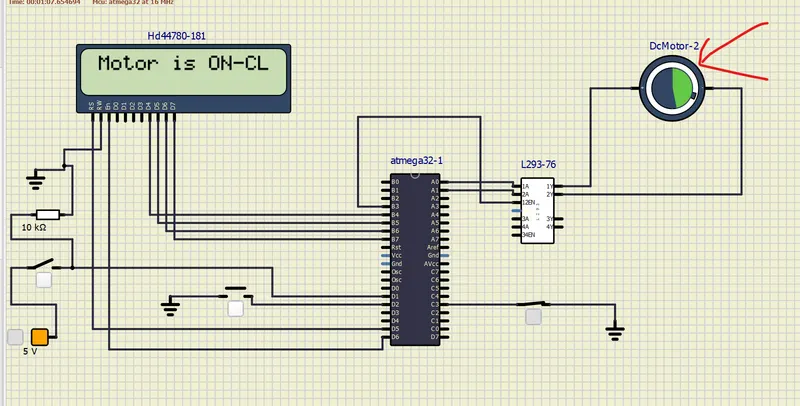
and here in this circuit we can see that the motor is rotating in clock wise direction and by pressing the port d 2nd connected push button the rapid speed increase to its maximum level by the formilae i=i+20
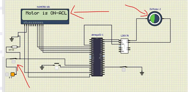
like wise when i pressed the port d 1 st pin connected push button the motor starts to rorate in anti clock wise direction and by pressing the port b 2 nd pin connected push button the rapid speed increase to its maximum value this formulae i= i+20