Project 1 - Controlling a DC motor using PWM and monitoring its Running status
Overview of the Project:
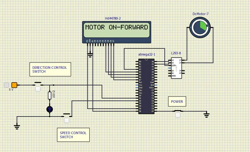
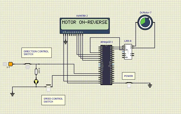
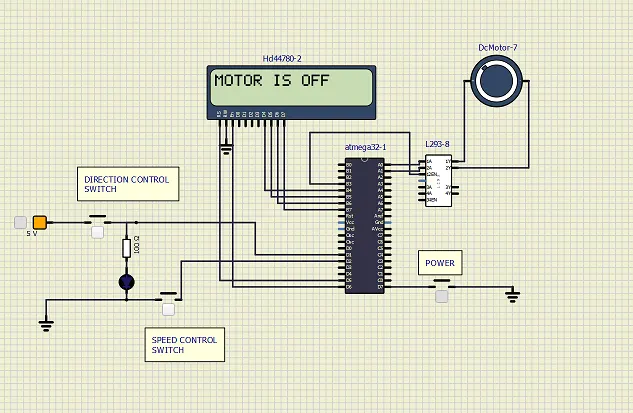
This is a code for controlling a DC motor using PWM (Pulse Width Modulation) technique and an AVR ATmega32 microcontroller. We are using an L293 DC motor driver and an LCD display. It also sets up an external interrupt INT0 for the direct control of the motor and reads the input switches for power on/off and controlling the speed of the motor.
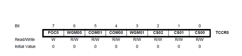
TCCR0 REGISTER(TIMER):
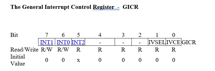
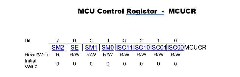
GICR AND MCUCR REGISTER (ISR):
#include  // Include AVR header file
#define F_CPU 16000000 // Define CPU frequency as 16 MHz
#include "avr/interrupt.h" // Include external interrupt header file
#include  // Include delay function header file

#define sw_direction (PIND & (1<<1)) // Define D1 pin as input switch for direction control
#define sw_speed (PIND & (1<<2)) // Define D2 pin as input switch for controlling speed
#define power (PIND & (1<<7)) // Define D7 pin as input switch for power on/off

#define lcd_port PORTB // Define PORTB pins for LCD data
#define RS_high PORTD |= (1<<5) // Set D5 register select pin high to select data register
#define RS_low PORTD &=~ (1<<5) // Set D5 register select pin low to select instruction register
#define EN_high PORTD |= (1<<6) // Set D6 enable pin high to enable data transfer
#define EN_low PORTD &=~ (1<<6) // Set D6 enable pin low to disable data transfer


unsigned char i;// global variable i
void lcd_cmd(char cmd) //command for lcd display
{
	lcd_port = (cmd & 0xF0); // send the higher 4 bits of the command to the LCD port
	RS_low; // command mode
	EN_low; // set the EN pin to low
	_delay_ms(1); // wait for 1 millisecond
	EN_high; // set the EN pin high to send the command to the LCD
	_delay_ms(1); // wait for 1 millisecond
	lcd_port = ((cmd<<4) & 0xF0); // send the higher 4 bits of the command to the LCD port
	RS_low; // command mode
	EN_low; // set the EN pin to low
	_delay_ms(1); // wait for 1 millisecond
	EN_high; // send lower 4 bits
	_delay_ms(1); // wait for 1 millisecond
}


// Function to send data to LCD
void lcd_data(unsigned char data) {
	lcd_port = data; // Send the lower 4 bits of data to the LCD data pins
	RS_high; // Set RS pin high to indicate that data is being sent
	EN_low; // Set EN pin low to prepare for enabling data transmission with delay
	_delay_ms(1);
	EN_high; // Set EN pin high to enable data transmission
	_delay_ms(1);
	lcd_port = ((data<<4) & (0xf0)); // Send the upper 4 bits of data to the LCD data pins
	RS_high; // Set RS pin high to indicate that data is being sent
	EN_low; // Set EN pin low to prepare for enabling data transmission with delay
	_delay_ms(1);
	EN_high; // Set EN pin high to enable data transmission
}

void lcd_init()
{
	lcd_cmd(0x38);_delay_ms(5);// used for 4 bit lcd mode WITH DELAY
	lcd_cmd(0x02);_delay_ms(5); // return home
	lcd_cmd(0x01); _delay_ms(5);// clear screen
    lcd_cmd(0x0C); _delay_ms(5);// display on cursor off
    lcd_cmd(0x06);	_delay_ms(5); // increment the display cursor
    lcd_cmd(0x80);_delay_ms(5); // force cursor to begin from 1st line
}

void cursorpos(char x, char y)
{
	if ((x<1 || x>2) || (y>16 || y<1)) // condition will check the 2 rows and 16 columns
	{
		x = 1; // x = row
		y = 1; // y = column
	}

	if (x == 1)
	{
		lcd_cmd(0x7F + y); // {80-1 = 7F} for starting the 1st line hex decimal value (80) {y we r using the 7F+y means we need to start from
	}
	else //(x==2)
	{
		lcd_cmd(0xBF + y); // {0C-1 = 0B} for starting the 2nd line, 2nd row.
	}
}


void lcd_out(char x, char y, char *str) //here we are checking which position we want to print
{
	cursorpos(x,y);
	while(*str)
	{
		lcd_data(*str);
		str++;
	}
}

int main(void)
{

	DDRB = 0xff; //Declaring all 8-pins as output FOR LCD.
    DDRA |= ((1<<0)| (1<<1)); //Declaring A0 & A1 pins as output FOR MOTOR DRIVER.
	DDRD &=~ (1<<1); //Declaring D1 pin as input.
	DDRD |= (1<<5); //Declaring D5 pin as output FOR RS.
	DDRD |= (1<<6); //Declaring D6 pin as output FOR EN.
	PORTD |= (1<<2); //Declaring D2 pin as input.
    PORTD |= (1<<7); //Declaring D7 pin as input.

	i=64; //256/4=64 running the motor with 25% duty cycle.

	TCCR0 |=0b01100001; //Non-Inverting mode, PWM phase correct mode,NO prescalar.
    sei(); //Enable global interrupt
	GICR=(1<
OUTPUT: