Project 1 - Controlling a DC motor using PWM and monitoring its Running status
In this Project below we have made a system to control speed and direction of rotation of DC motor using PWM. In this project 2 external interrupt are used for speed increase and decrease and one input pin with switch to change direction of rotation along with it we have used motor driver H-B ridge L293 and a DC motor also one LCD is used to see running status of Motor
Circuit Diagram:
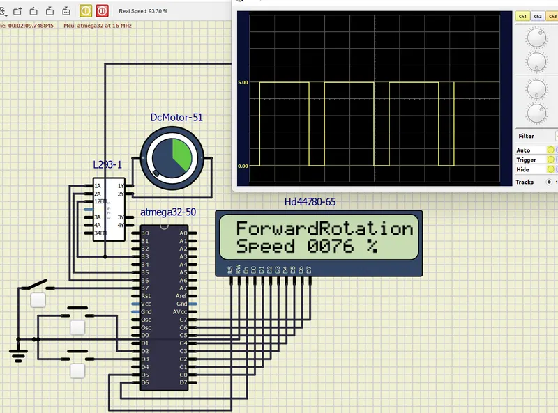
Code:
/*
* BMProject1.c
*
* Created: 16-02-2023 14:51:56
* Author : Lenovo
*/
#include <avr/io.h>
#define F_CPU 16000000UL // 16MHz
#include <util/delay.h>
#include <avr/interrupt.h>
unsigned char i= 20; // variaable to hold OCR0 values
#define rs_high() PORTD |=(1<<5);
#define rs_low() PORTD &= ~(1<<5);
#define en_high() PORTD |= (1<<6);
#define en_low() PORTD &= ~(1<<6);
#define lcdport PORTC
void lcd_command(unsigned char cmd);
void lcd_data(unsigned char data);
void lcd_init();
void cursorpos(char x, char y);
void lcd_print(char row, char column, unsigned int value, int digits);
void lcd_out(char x, char y, char *str);
void lcd_command(unsigned char cmd)
{
lcdport = cmd;
rs_low();
en_high();
_delay_ms(1);
en_low();
}
void lcd_data(unsigned char data)
{
lcdport = data;
rs_high();
en_high();
_delay_ms(1);
en_low();
}
void lcd_init()
{
lcd_command(0x38);_delay_ms(500);
lcd_command(0x02);_delay_ms(500);
lcd_command(0x01);_delay_ms(5);
lcd_command(0x0c);_delay_ms(5);
lcd_command(0x06);_delay_ms(5);
lcd_command(0x80);_delay_ms(5);
}
void cursorpos(char x, char y)
{
if( (x < 1 || x > 2) || (y < 1 || y > 16) )
{
x = 1;
y = 1;
}
if(x == 1)
lcd_command(0x80+y);
else
lcd_command(0xC0+y);
}
void lcd_print(char row, char coloumn, unsigned int value, int digits)
{
unsigned int temp;
unsigned int unit;
unsigned int tens;
unsigned int hundred;
unsigned int thousand;
unsigned int million;
unsigned char flag=0;
if(row==0||coloumn==0)
{
cursorpos(1,1);
}
else
{
cursorpos(row,coloumn);
}
if(digits==5|| flag==1)
{
million=value/10000+48;
lcd_data(million);
flag=1;
}
if(digits==4 || flag==1)
{
temp = value/1000;
thousand = temp%10 +48;
lcd_data(thousand);
flag=1;
}
if(digits==3 || flag==1)
{
temp = value/100;
hundred = temp%10 +48;
lcd_data(hundred);
flag=1;
}
if(digits==2 || flag==1)
{
temp = value/10;
tens= temp%10 +48;
lcd_data(tens);
flag=1;
}
if(digits==1 || flag==1)
{
unit = value%10 + 48;
lcd_data(unit);
}
if(digits>5)
{
lcd_data('e');
}
}
void lcd_out(char x,char y,char *str)
{
cursorpos(x,y);
while(*str)
{
lcd_data(*str);
str++;
}
}
int main(void)
{
// Non Inverted Mode (Clear OC0 on compare match) , PWM Phase correct mode
// TCCR0 = 0b01100011 = 0x63
float j=0;
lcd_init();
// Configure PORTB bit 3 as output. It is also OC0 status pin also so..
DDRB = 0b01101000; // Configure PORTB bit 3 as output for PWM and bit 5,6 for motor polarity. and bit 7 as input for direction control
PORTB |= (1<<PB7); // Activate pull up
DDRD &=~((1<<PD2)|(1<<PD3)); // Make PD2 and PD3 as i/p pin (INT0, INT1 pin)
PORTD |= ((1<<PD2)|(1<<PD3)); // Activate pull up
GICR = ((1<<INT0)|(1<<INT1)); //Enable external interrupt0,1
MCUCR = 0x0A; // Make interrrupt0,1 negative edge triggered
sei(); // enable interrupts
TCNT0 = 0;
TCCR0 = 0x61; // Phase correct PWM, No prescaler, Non Inverted Mode
while(1)
{
if(i>250)
{
i=250;
}
if(i<20)
{
i=20;
}
OCR0 = i; // duty cycle 7.8% as i = 20 initially.
if (((PINB)&(1<<PB7))==0)// switch closed indicating anti clock wise rotation
{
PORTB |=(1<<PB5);
PORTB &=~(1<<PB6);
lcd_out(1,1," Back Rotation");
}
else // switch open indicating clock wise rotation
{
PORTB |=(1<<PB6);
PORTB &=~(1<<PB5);
lcd_out(1,1,"ForwardRotation");
}
j=(float)i;
j=(j*100)/255.0;
lcd_out(2,1,"Speed");
lcd_print(2,7,j,4);
lcd_out(2,12,"%");
}
return(0);
}
ISR(INT0_vect)// accelerating - gradually increase speed
{
i=i+5;
}
ISR(INT1_vect) // deaccelerating - gradually decreasing speed
{
i=i-5;
}