Project 1 - Controlling a DC motor using PWM and monitoring its Running status
Answer:-
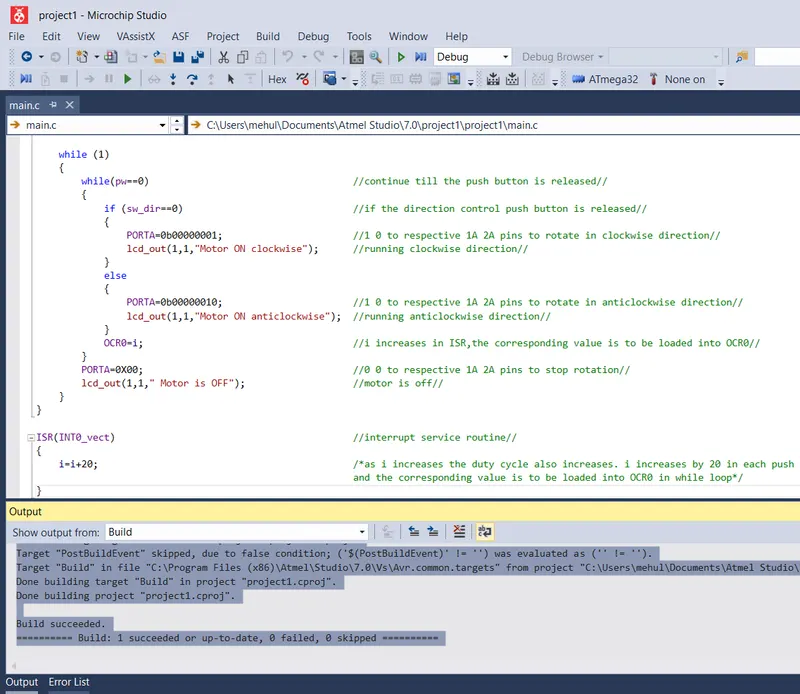
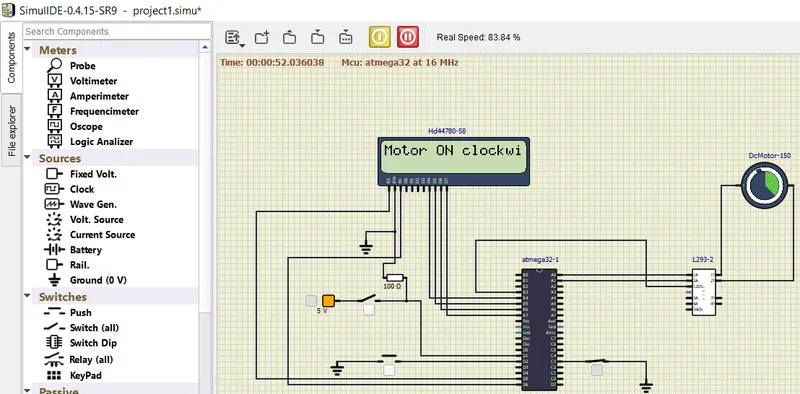
AIM:- Implement a system on the simulator for controlling a DC motor using L293 motor driver, monitor its status and print the running status of motor on the LCD Display.
CODE:-
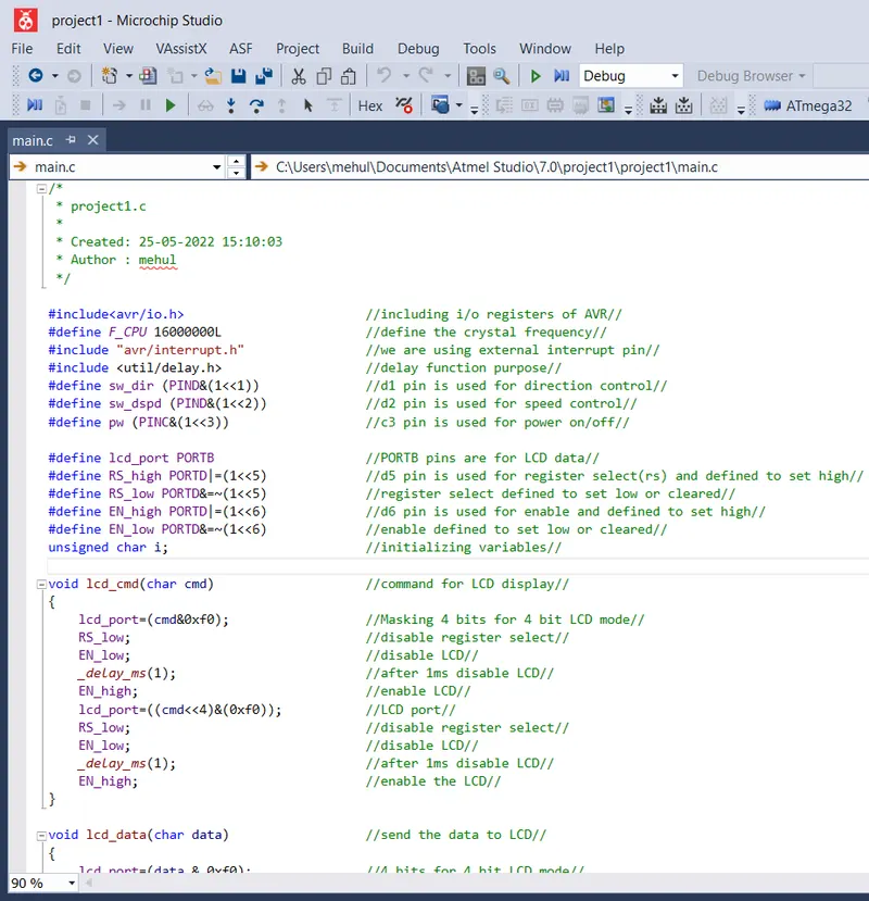
/*
* project1.c
*
* Created: 25-05-2022 15:10:03
* Author : mehul
*/
#include<avr/io.h> //including i/o registers of AVR//
#define F_CPU 16000000L //define the crystal frequency//
#include "avr/interrupt.h" //we are using external interrupt pin//
#include <util/delay.h> //delay function purpose//
#define sw_dir (PIND&(1<<1)) //d1 pin is used for direction control//
#define sw_dspd (PIND&(1<<2)) //d2 pin is used for speed control//
#define pw (PINC&(1<<3)) //c3 pin is used for power on/off//
#define lcd_port PORTB //PORTB pins are for LCD data//
#define RS_high PORTD|=(1<<5) //d5 pin is used for register select(rs) and defined to set high//
#define RS_low PORTD&=~(1<<5) //register select defined to set low or cleared//
#define EN_high PORTD|=(1<<6) //d6 pin is used for enable and defined to set high//
#define EN_low PORTD&=~(1<<6) //enable defined to set low or cleared//
unsigned char i; //initializing variables//
void lcd_cmd(char cmd) //command for LCD display//
{
lcd_port=(cmd&0xf0); //Masking 4 bits for 4 bit LCD mode//
RS_low; //disable register select//
EN_low; //disable LCD//
_delay_ms(1); //after 1ms disable LCD//
EN_high; //enable LCD//
lcd_port=((cmd<<4)&(0xf0)); //LCD port//
RS_low; //disable register select//
EN_low; //disable LCD//
_delay_ms(1); //after 1ms disable LCD//
EN_high; //enable the LCD//
}
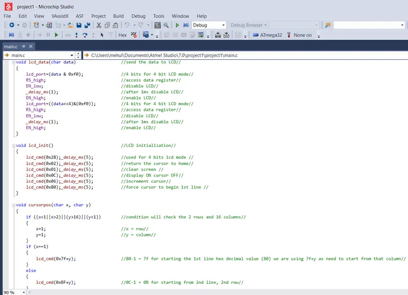
void lcd_data(char data) //send the data to LCD//
{
lcd_port=(data & 0xf0); //4 bits for 4 bit LCD mode//
RS_high; //access data register//
EN_low; //disable LCD//
_delay_ms(1); //after 1ms disable LCD//
EN_high; //enable LCD//
lcd_port=((data<<4)&(0xf0)); //4 bits for 4 bit LCD mode//
RS_high; //access data register//
EN_low; //disable LCD//
_delay_ms(1); //after 1ms disable LCD//
EN_high; //enable LCD//
}
void lcd_init() //LCD initialization//
{
lcd_cmd(0x28);_delay_ms(5); //used for 4 bits lcd mode //
lcd_cmd(0x02);_delay_ms(5); //return the cursor to home//
lcd_cmd(0x01);_delay_ms(5); //clear screen //
lcd_cmd(0x0C);_delay_ms(5); //display ON cursor OFF//
lcd_cmd(0x06);_delay_ms(5); //increment cursor//
lcd_cmd(0x80);_delay_ms(5); //force cursor to begin 1st line //
}
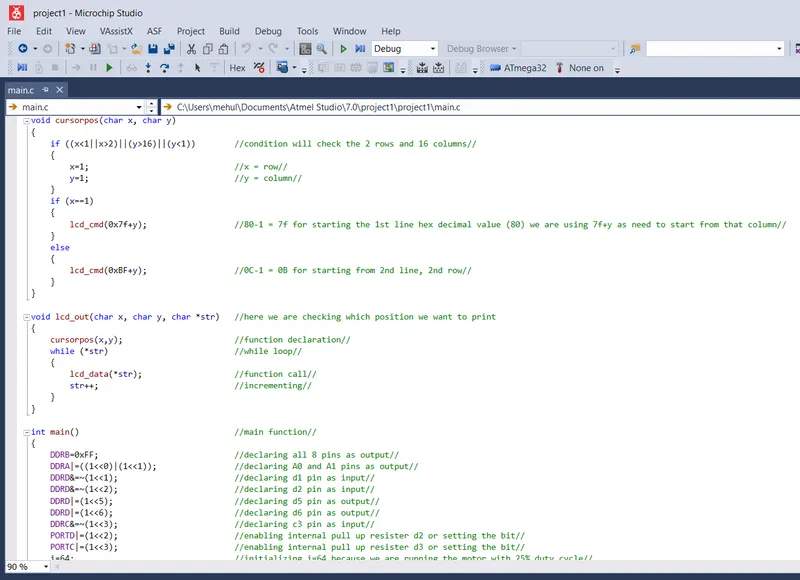
void cursorpos(char x, char y)
{
if ((x<1||x>2)||(y>16)||(y<1)) //condition will check the 2 rows and 16 columns//
{
x=1; //x = row//
y=1; //y = column//
}
if (x==1)
{
lcd_cmd(0x7f+y); //80-1 = 7f for starting the 1st line hex decimal value (80) we are using 7f+y as need to start from that column//
}
else
{
lcd_cmd(0xBF+y); //0C-1 = 0B for starting from 2nd line, 2nd row//
}
}
void lcd_out(char x, char y, char *str) //here we are checking which position we want to print
{
cursorpos(x,y); //function declaration//
while (*str) //while loop//
{
lcd_data(*str); //function call//
str++; //incrementing//
}
}
int main() //main function//
{
DDRB=0xFF; //declaring all 8 pins as output//
DDRA|=((1<<0)|(1<<1)); //declaring A0 and A1 pins as output//
DDRD&=~(1<<1); //declaring d1 pin as input//
DDRD&=~(1<<2); //declaring d2 pin as input//
DDRD|=(1<<5); //declaring d5 pin as output//
DDRD|=(1<<6); //declaring d6 pin as output//
DDRC&=~(1<<3); //declaring c3 pin as input//
PORTD|=(1<<2); //enabling internal pull up resister d2 or setting the bit//
PORTC|=(1<<3); //enabling internal pull up resister d3 or setting the bit//
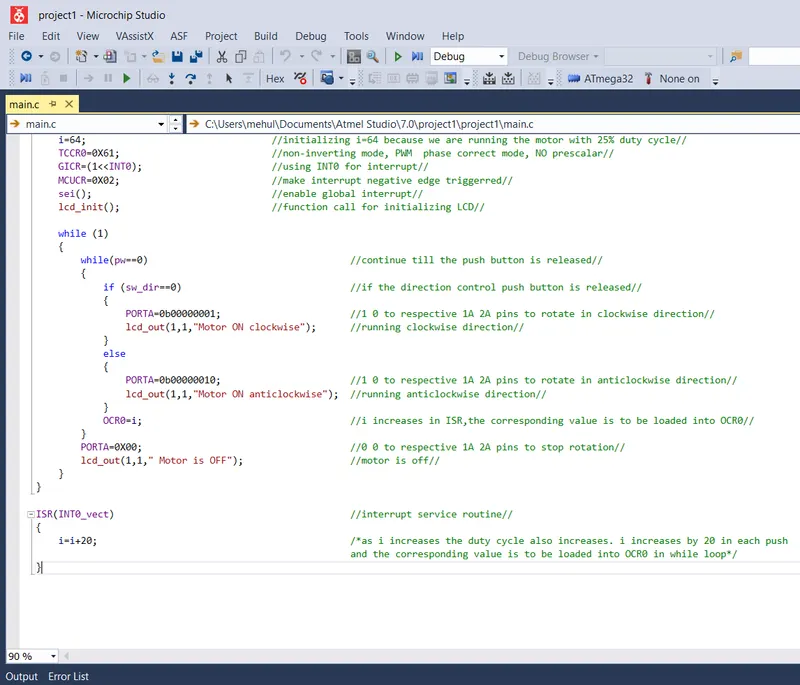
i=64; //initializing i=64 because we are running the motor with 25% duty cycle//
TCCR0=0X61; //non-inverting mode, PWM phase correct mode, NO prescalar//
GICR=(1<<INT0); //using INT0 for interrupt//
MCUCR=0X02; //make interrupt negative edge triggerred//
sei(); //enable global interrupt//
lcd_init(); //function call for initializing LCD//
while (1)
{
while(pw==0) //continue till the push button is released//
{
if (sw_dir==0) //if the direction control push button is released//
{
PORTA=0b00000001; //1 0 to respective 1A 2A pins to rotate in clockwise direction//
lcd_out(1,1,"Motor ON clockwise"); //running clockwise direction//
}
else
{
PORTA=0b00000010; //1 0 to respective 1A 2A pins to rotate in anticlockwise direction//
lcd_out(1,1,"Motor ON anticlockwise"); //running anticlockwise direction//
}
OCR0=i; //i increases in ISR,the corresponding value is to be loaded into OCR0//
}
PORTA=0X00; //0 0 to respective 1A 2A pins to stop rotation//
lcd_out(1,1," Motor is OFF"); //motor is off//
}
}
ISR(INT0_vect) //interrupt service routine//
{
i=i+20; /*as i increases the duty cycle also increases. i increases by 20 in each push
and the corresponding value is to be loaded into OCR0 in while loop*/
}
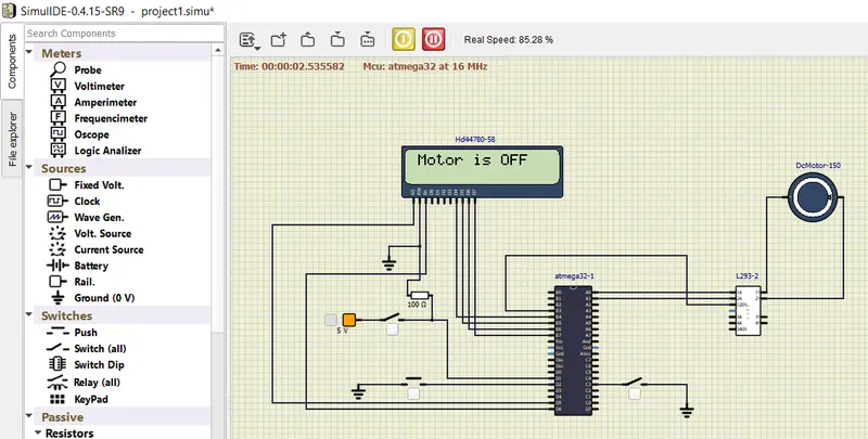
OUTPUT WINDOW:-
Power Switch: OFF, Direction Switch: OFF, Speed Switch: OFF :: Motor in TURN OFF Condition
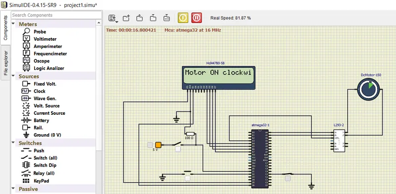
Power Switch: ON, Direction Switch: OFF, Speed Switch: OFF :: Motor is on clockwise condition.
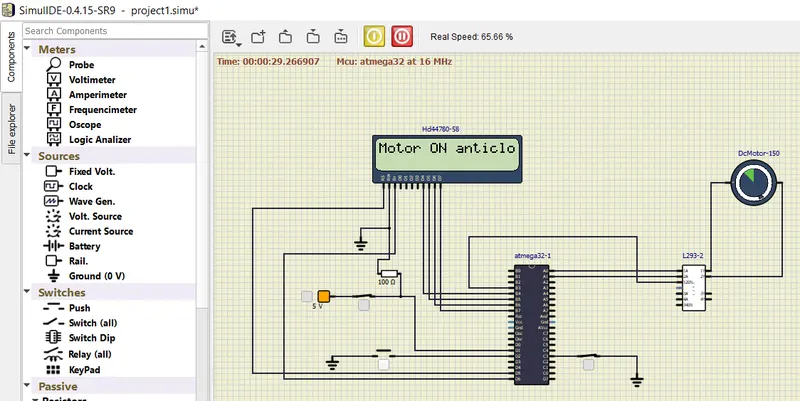
Power Switch: ON, Direction Switch: ON, Speed Switch: OFF :: Motor is ON and Anti clockwise.
Power Switch: ON, Direction Switch: OFF,Speed Switch: ON :: Motor is ON and speed of motor is increased.
Goals:
- Implementation of a system on simulator for Controlling the DC motor using L293 motor driver was achieved.
- Display of the running status of DC motor on the LCD display was achieved.
Key Highlights of the Project:
- The DC motor can be controlled by using L293 motor driver.
- The speed of a DC motor can be controlled by varying its input voltage, for doing this is to use PWM (Pulse Width Modulation).
- L293D IC is a typical Motor Driver IC which allows the DC motor to drive on any direction.
Deliverables of this project:
- Implementation of the system for controlling DC motor.
- Controlling the speed of the DC motor using PMW was achieved by speed switch.
- Displaying the present running status of DC machine on LCD display was achieved.
Expected Outcomes:
- Implementation of a system on simulator to control a DC motor using PMW was achieved and the output shown in output window.
- Monitored the running status of the DC motor using L293 motor driver which allows the DC motor to drive on any direction.
- Running status i.e. on which direction the DC motor is running is displayed on the LCD screen.