Project 1_Comparative study of different storey buildings for Seismic forces
Aim:
- To extract different seismic response of a structure and to alter certain properties using ETABS software.
- To know factors influencing the dynamic characteristics of a building.
- To know factors influencing the Natural Period of a building.
- To know factors influencing the Mode shape of oscillations.
Introduction:
- ETABS is an engineering software product that caters to multi-story building analysis and design.
- ETABS stands for Extended Three-Dimensional Analysis of Building System.
Procedure:
- Open ETABS home page.
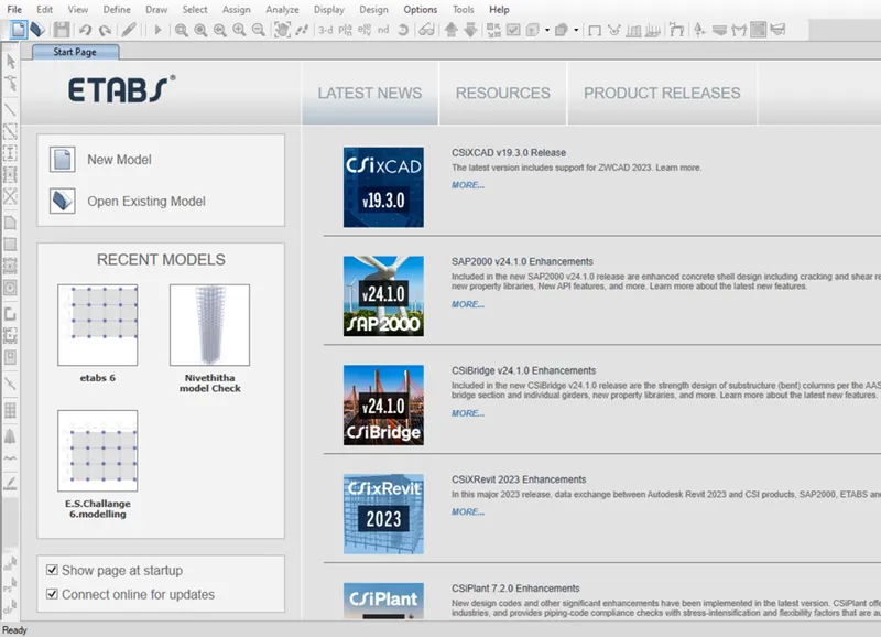
- Go to file-> New model and give the following setting.
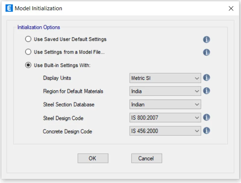
- Click ok
- For Building A:
- Grid spacing and story data:
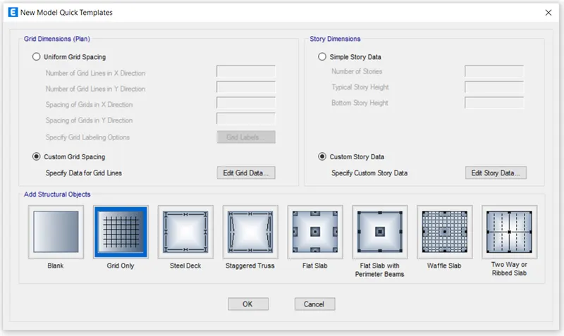
- Give the following option for grid dimension and story dimension in new model quick template as shown below.
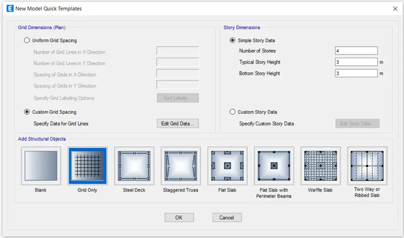
- Click edit grid data
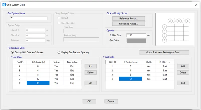
- Click edit story data
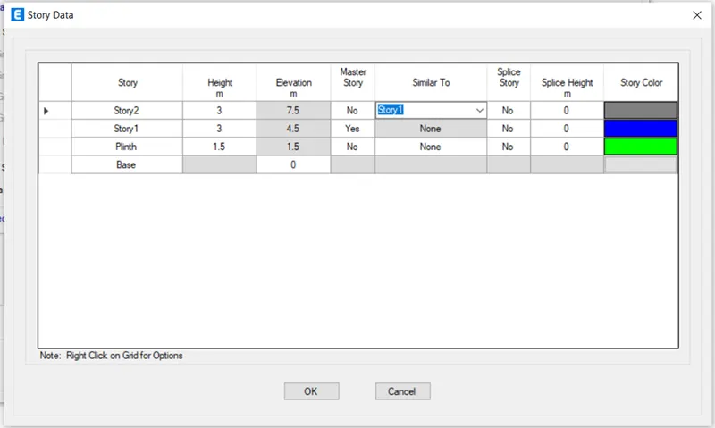
- Click ok
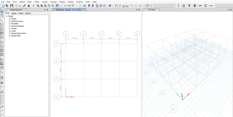
- The following screen opens.
- Defining Material properties:
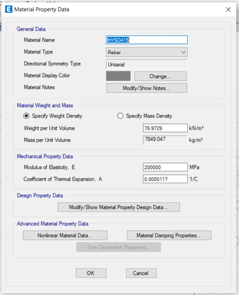
- For selecting material for rebars, Click Define-> Material properties-> Add new material
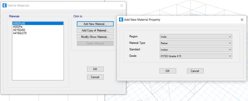
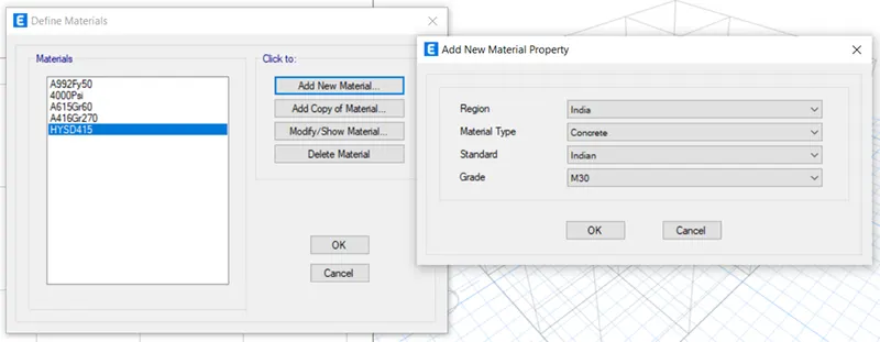
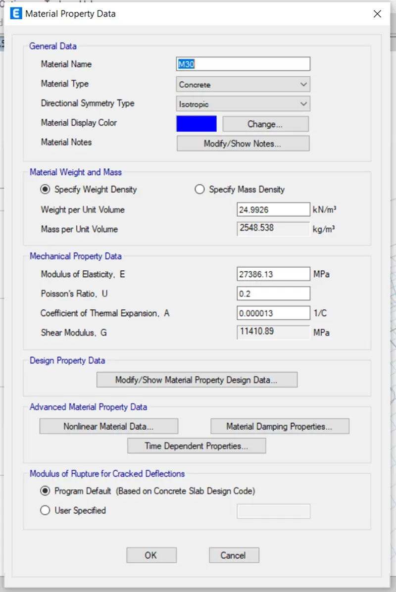
- Click ok and select new material for concrete.
- Defining Section property:
- For beam
- Click Define ->Section properties -> Frame section -> Add new property.
- Select the shape as rectangle
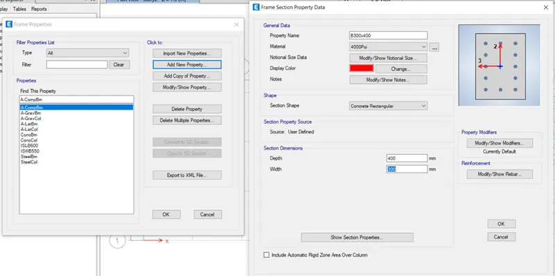
- Add beam size B300x400.
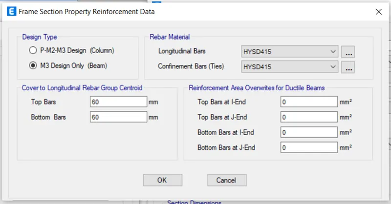
- For reinforcement detail for beam, Click Modify/ Show rebars button to give following data.
- Click ok.
- For column:
- Click add new property
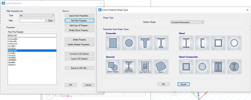
- Select the shape as rectangle
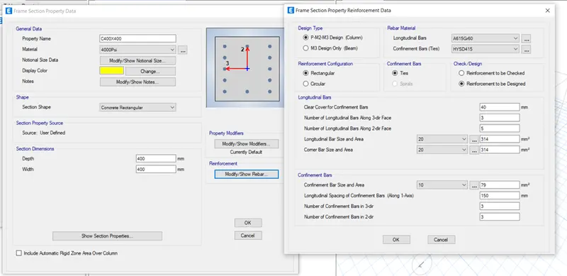
- For reinforcement detail for column, Click Modify/ Show rebars button to give following data.
- Click ok
- For slab:
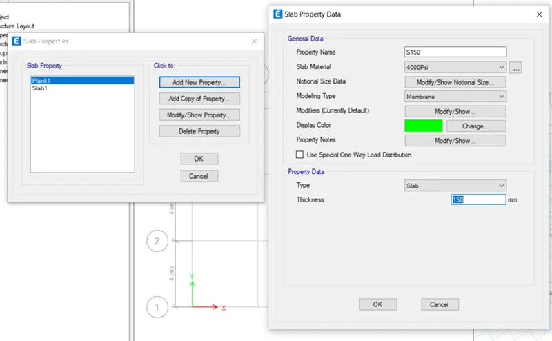
- Go to Define -> Section property -> Slab section -> Add new property.
- Click ok.
- Defining load patterns:
- Go to Define-> Load patterns
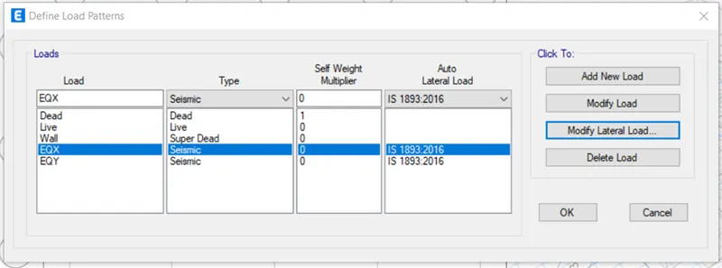
- Enter additional loads and give above data and click add new load.
- Click Modify Lateral Load for both seismic types respectively.
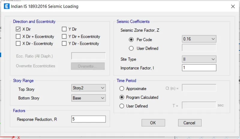
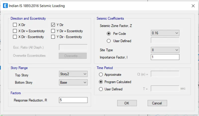
- Click ok.
- Defining mass source:
- Go to Define -> Mass source -> Modify/ show mass source
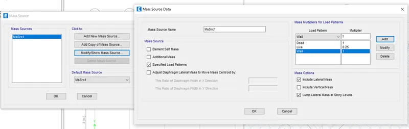
- Add mass multiplier for load pattern as above and click ok.
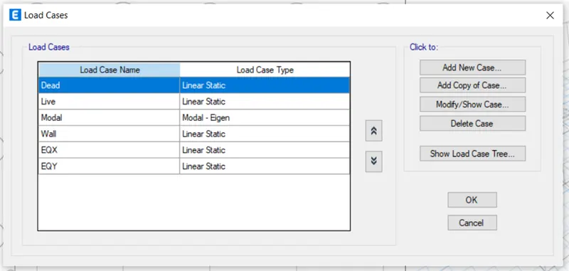
- Check the load cases:
- Go to Define -> Load cases.
- Create load combination:
- Go to Define -> Load combination ->Add default design combination.
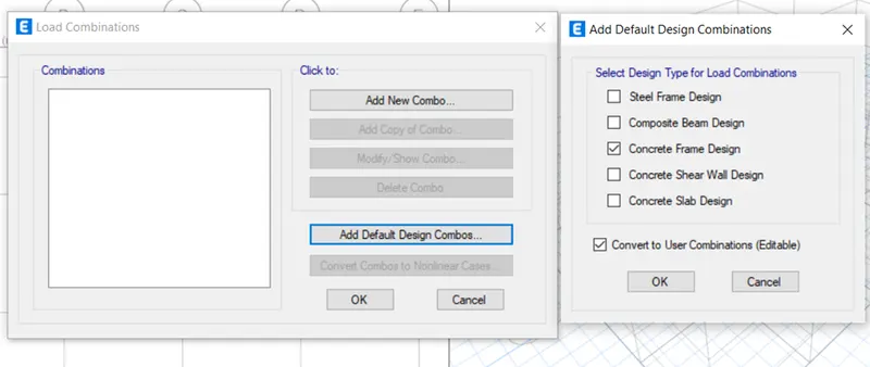
- Click ok
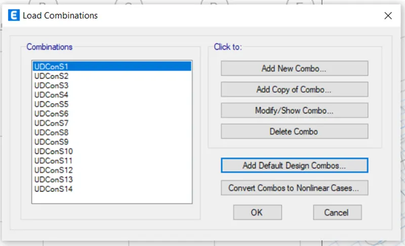
- Combination has created.
- Modeling:
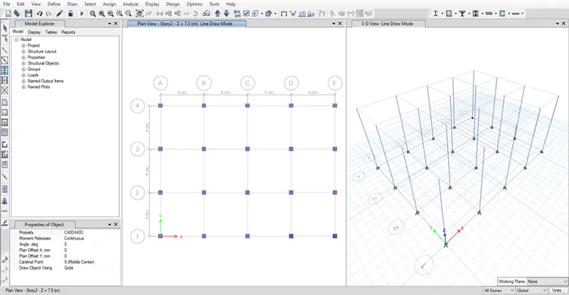
- To create Column:
- Select Quick draw column icon in the panel and select the column property type as C400X400.
- Select All story option in the bottom right.
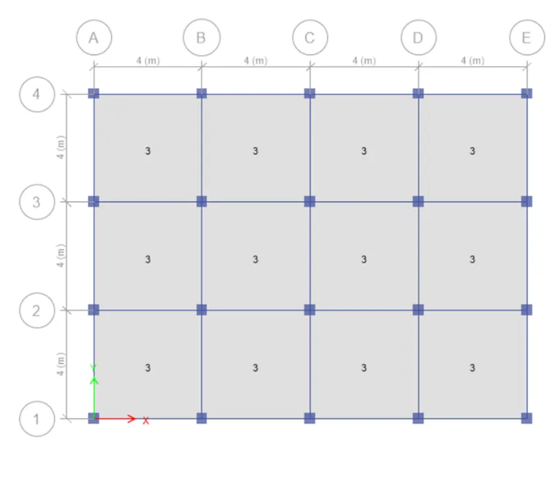
- Move the cursor on the grid and click to create column as shown below.
- To create beam:
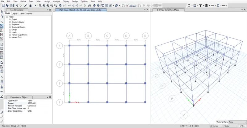
- Select Quick draw beam icon in the panel and select the beam property type as B300X400.
- Select All story option in the bottom right.
- Move the cursor on the line in between the grids and click to create beam as shown below.
- To create slab:
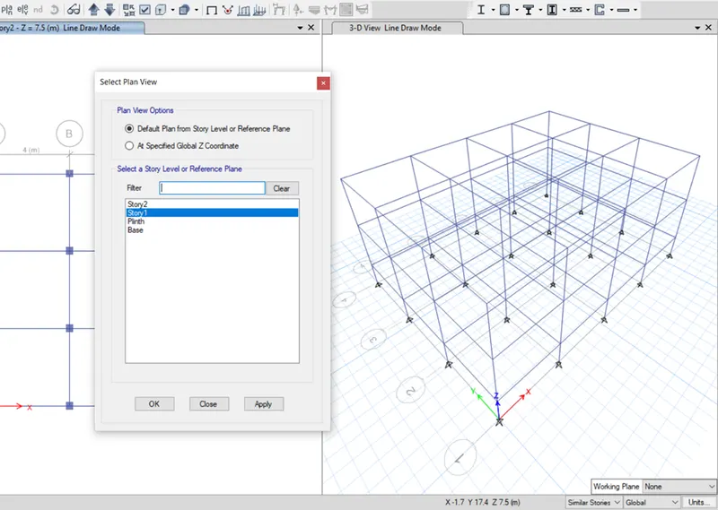
- Select similar stories option in the bottom right.
- Click plan icon on top of the panel and select the storey 1.
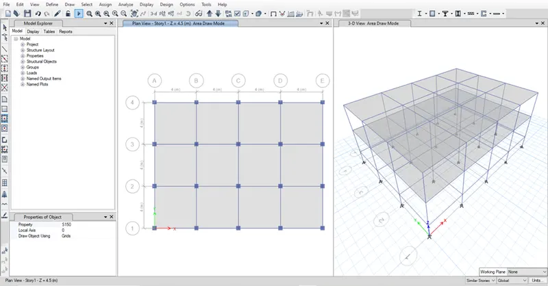
- Select Quick draw floor icon and select slab property type as S150.
- Click inside the frame.
- The slabs are created in the similar stories.
- To assign the loads:
- Select set of particular elements and assign loads.
- Beam:
- Go to Select -> Select -> Property –> Frame section
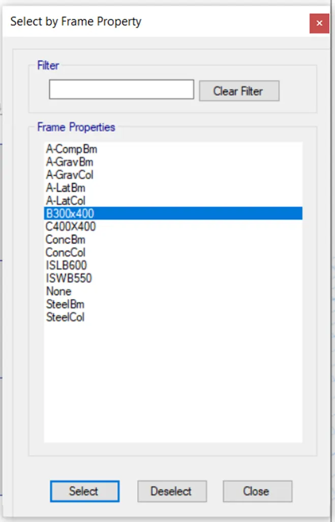
- Select the beam type.
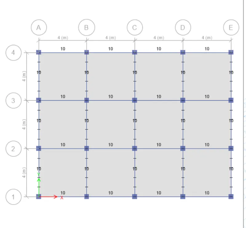
- Go to Assign-> Frame loads-> Distributed.
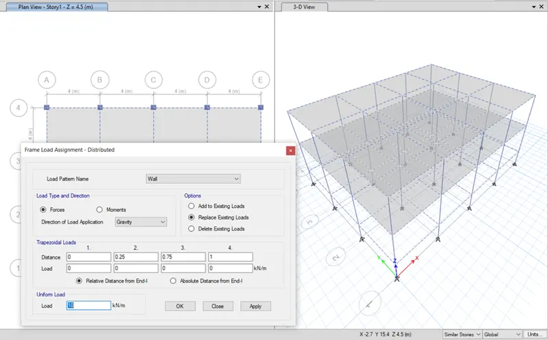
- Give load pattern and load as mentioned above.
- Slabs:
- Select slab property as S150
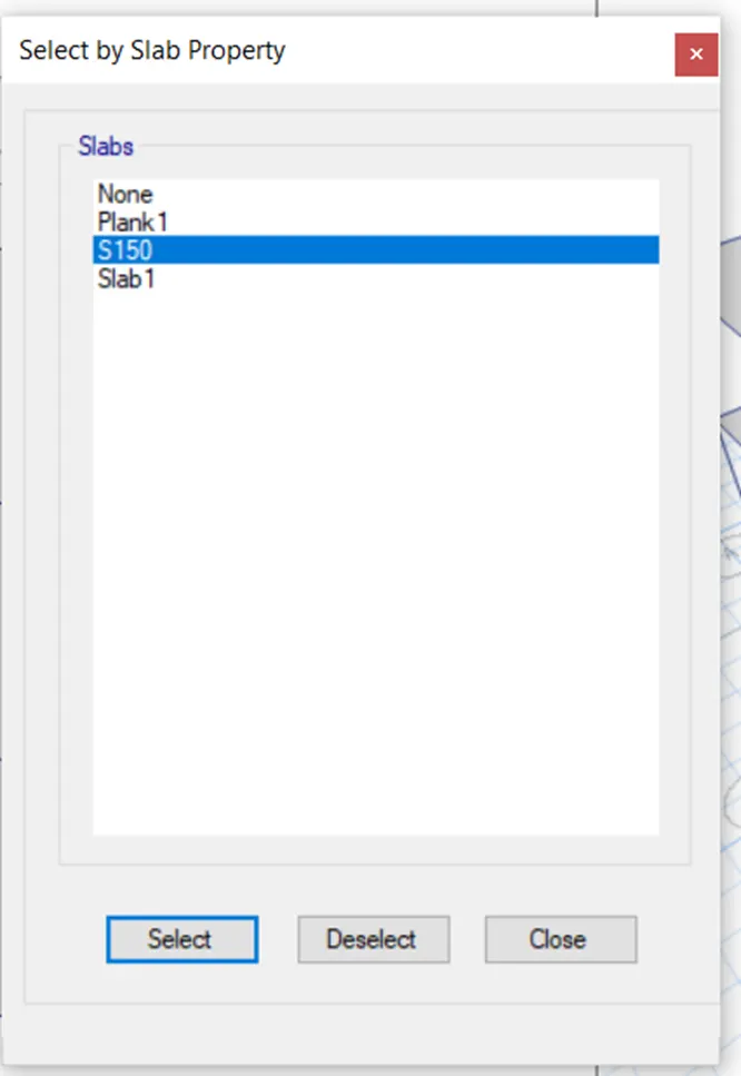
- Go to Select -> Select -> Property –> Slab section
- Go to Assign-> Shell loads->Uniform.
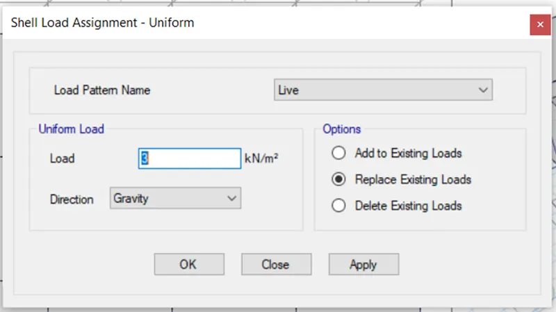
- Select the above load pattern and load and click ok.
- Again, go to Select -> Select -> Property –> Slab section
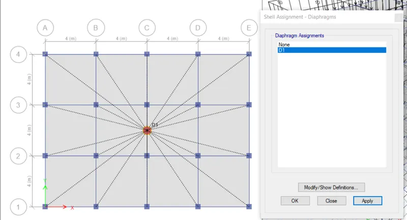
- Select Assign -> Shell -> Diaphragms -> D1.
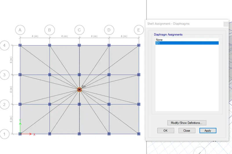
- Click ok.
- Save the model:
- To run the analysis:
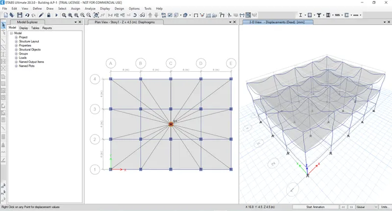
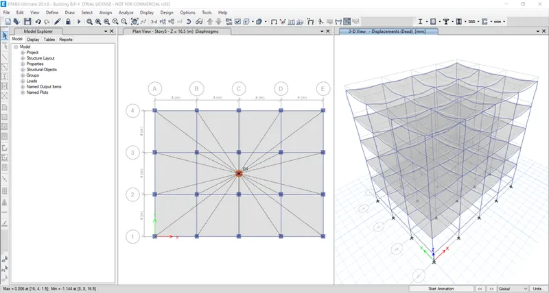
- Click Run analysis button on the top panel.
- Deformed shaped of the building is provided
- For Building B:
- Save as:
- Go to File -> Save as ‘Model B’
- Adding stories:
- To add extra stories, go to Edit -> Edit story and grid system -> Modify/ Show story data.
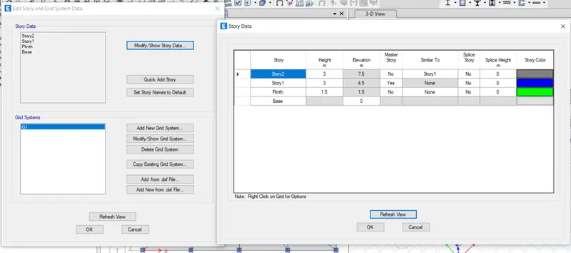
- Place the cursor on the arrow cell and right click -> add story -> keep existing story heights, and then give the below option in the dialog box.
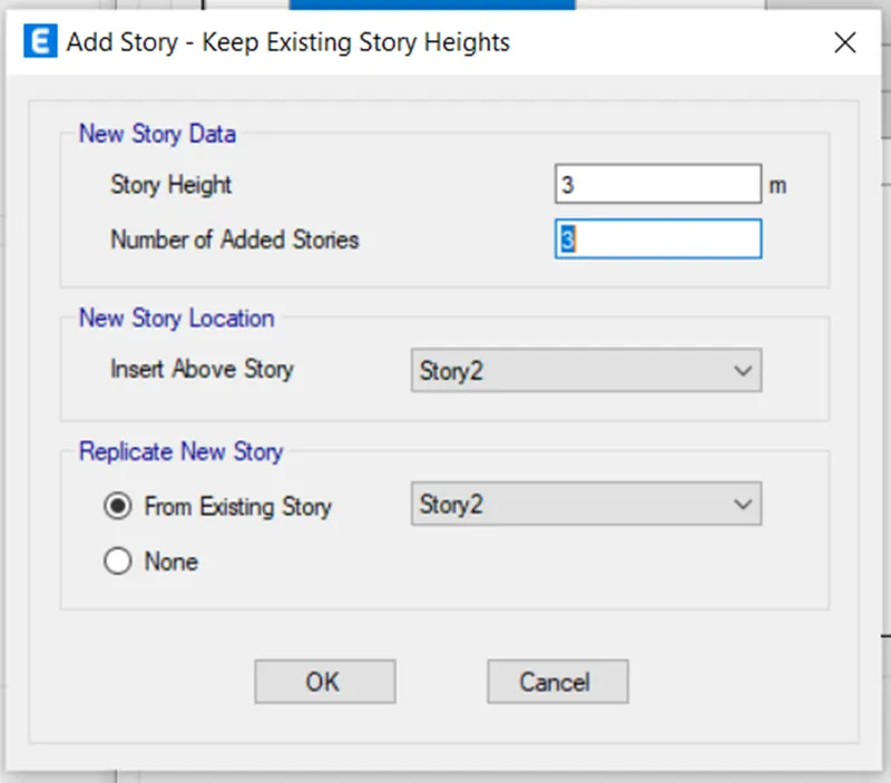
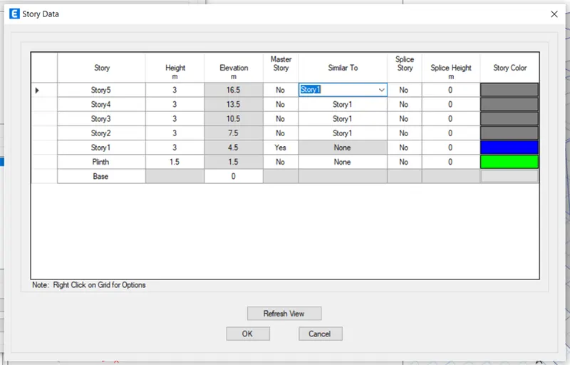
- Change similar to option to story 1.
- Click refresh view.
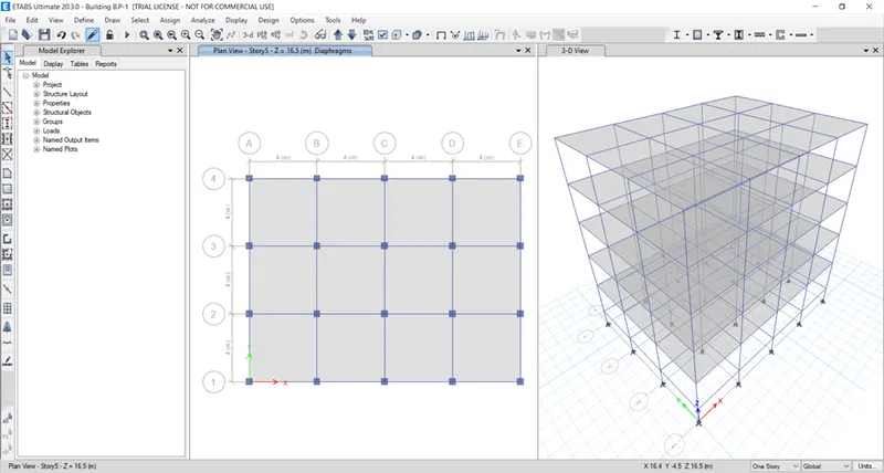
- Loads:
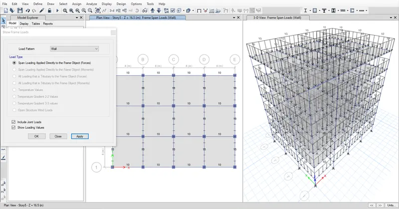
- Click Display shell load assign icon in the panel, Change the load pattern to live and click apply and ok.
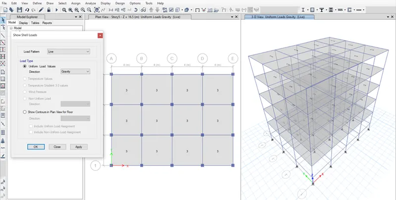
- Click Display frame load assigns icon in the panel, Change the load pattern to wall and click apply and ok.
- Select the slab S150 and assign it as diaphragm as mentioned in earlier steps.
- Analysis:
- Click run analysis icon.
- Building c:
- Save as:
- Click File -> Save the file
- Changing column property:
- Go to Define -> Section property -> Frame section
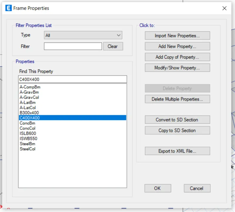
- Select the column and click Modify/ show property
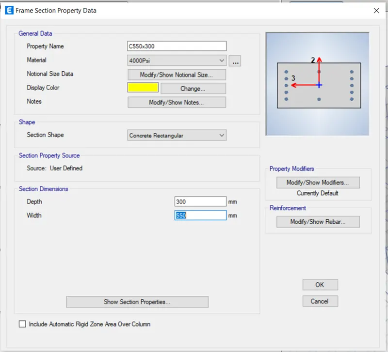
- Change the column size to 550X300.
- Click ok
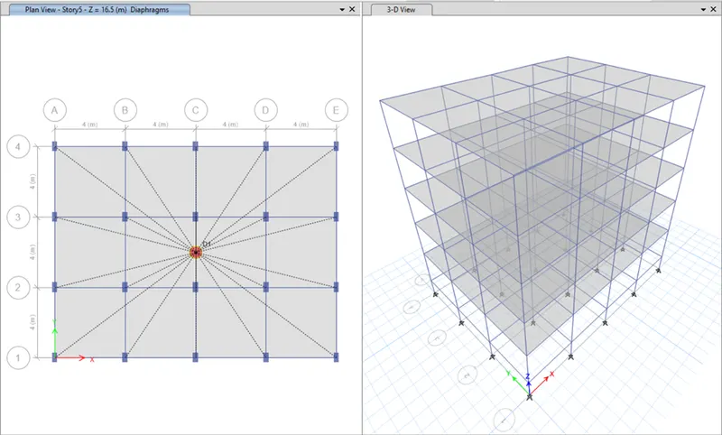
- Changing Column orientation in X- direction:
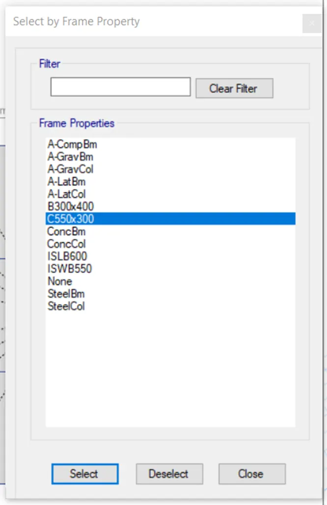
- Click Select -> Properties -> Frame section
- And select the column which created now and click Select.
- Click Assign -> Frame -> Local axes.
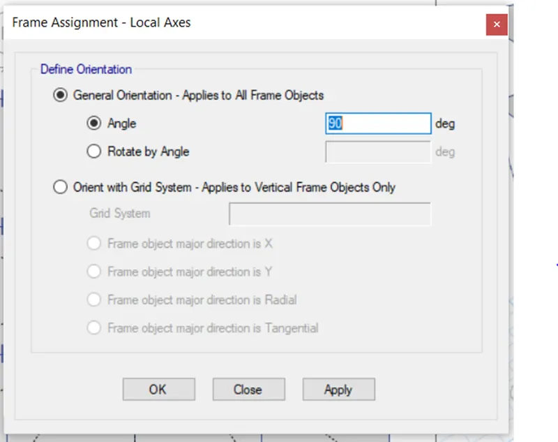
- Give Orientational degree as 90.
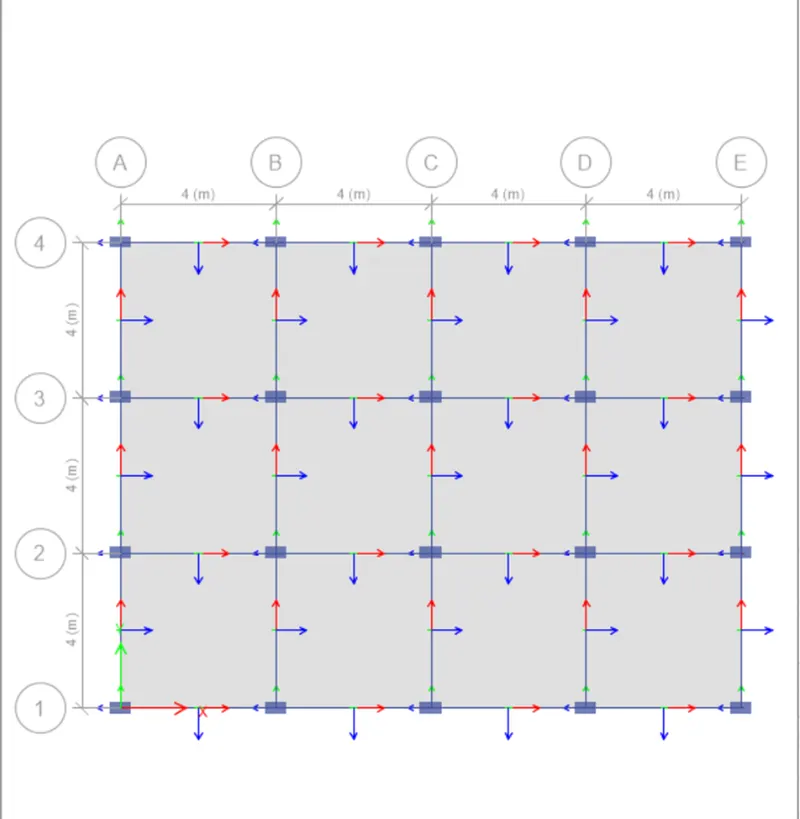
- Select the slab and assign it as diaphragm.
- Analysis:
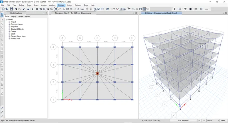
- Click run analysis icon.
- Building D:
- Save as:
- Click File -> Save the file
- Changing Column orientation in Y- direction:
- Click Select -> Properties -> Frame section
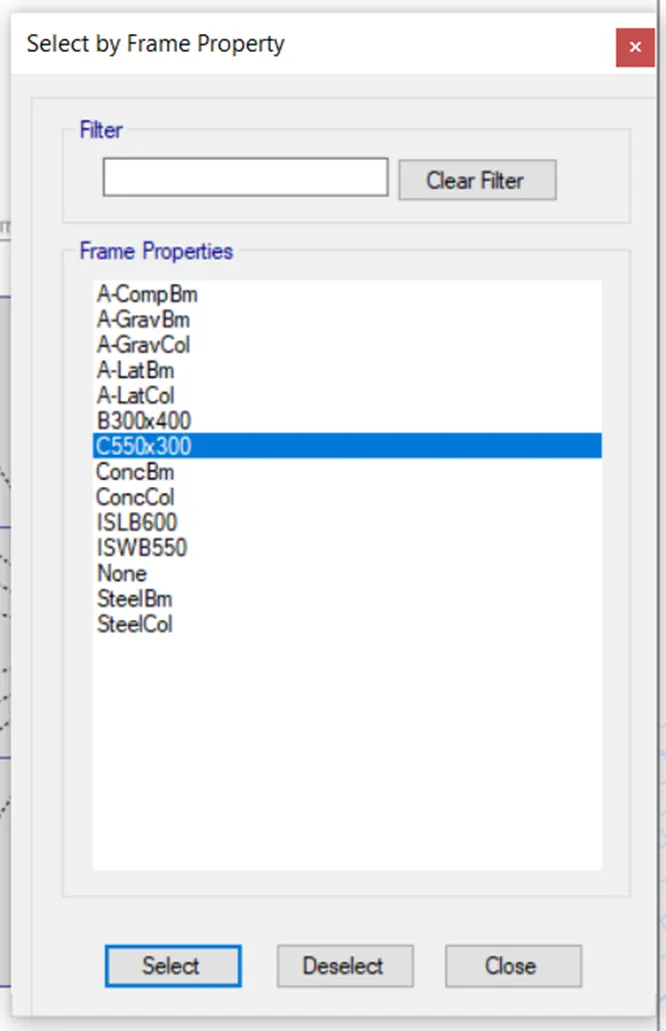
- And select the column which created now and click Select.
- Click Assign -> Frame -> Local axes.
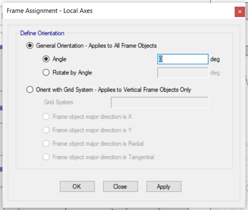
- Change angle to 0.
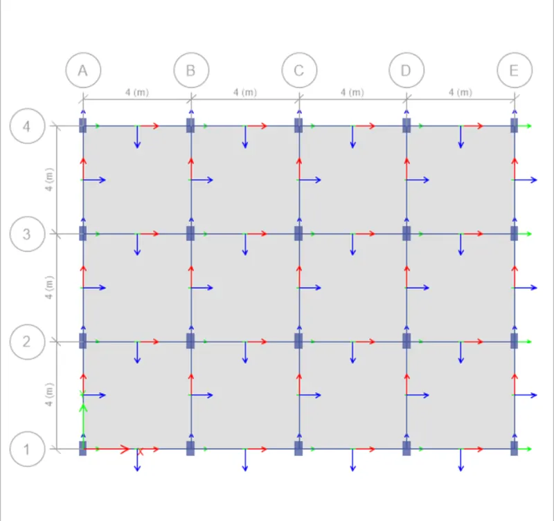
- Select the slab and assign it as diaphragm.
- Analysis:
- Click run analysis icon.
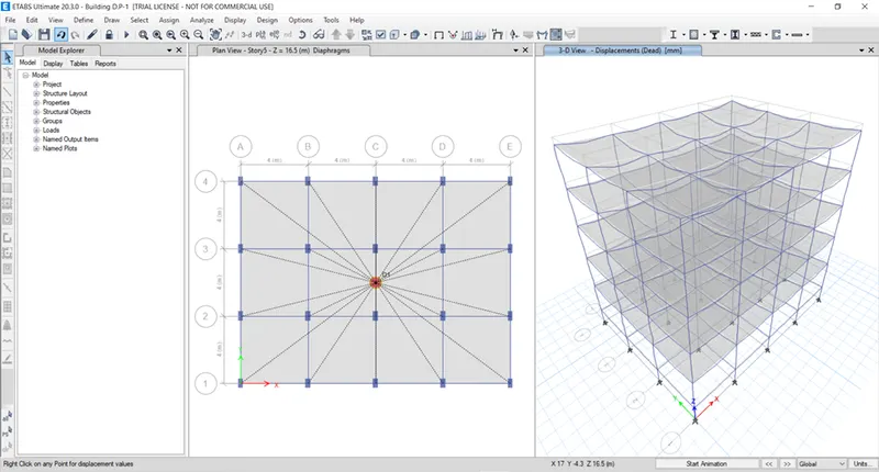
- Building E:
- Save as:
- Click File -> Save the file
- Adding stories:
- To add extra stories, go to Edit -> Edit story and grid system -> Modify/ Show story data.
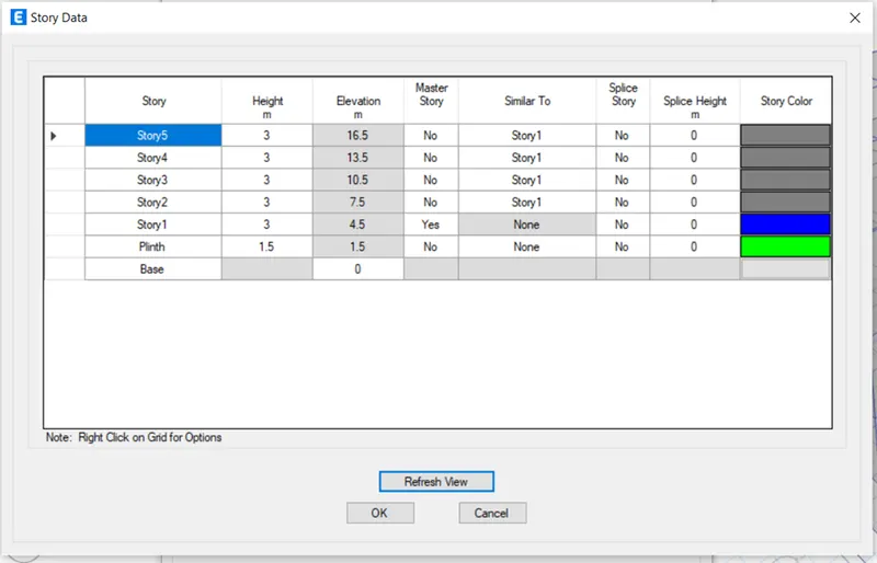
- Place the cursor on the arrow cell and right click -> add story -> keep existing story heights, and then give the below option in the dialog box.
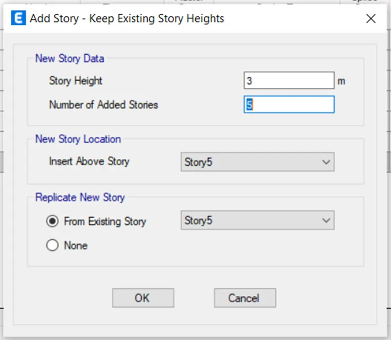
- Change similar to option as story 1.
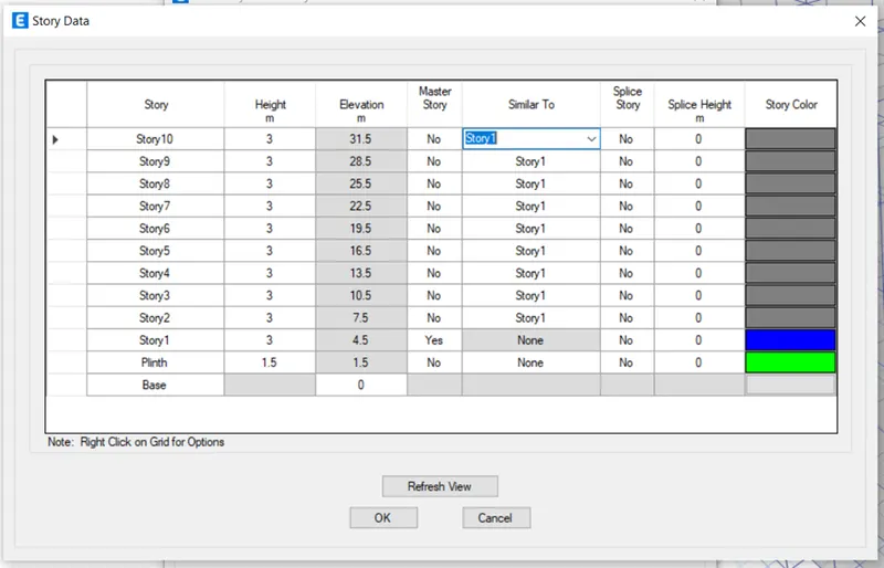
- Click refresh.
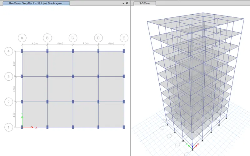
- Check the loading as mentioned in the earlier steps.
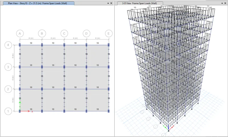
- Changing column size:
- Click Define -> Section property -> Frame section
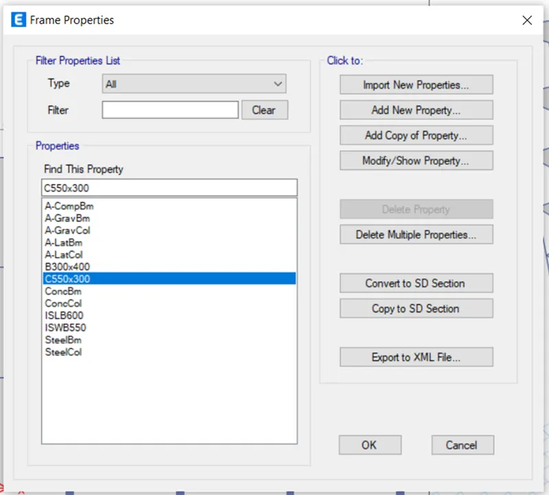
- Click column and select Modify/ show property.
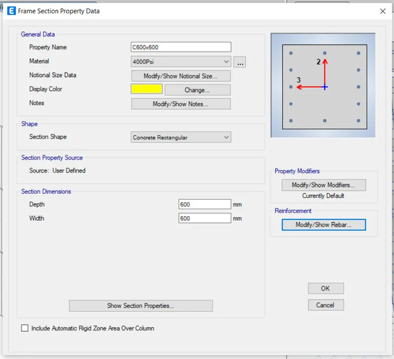
- Click ok
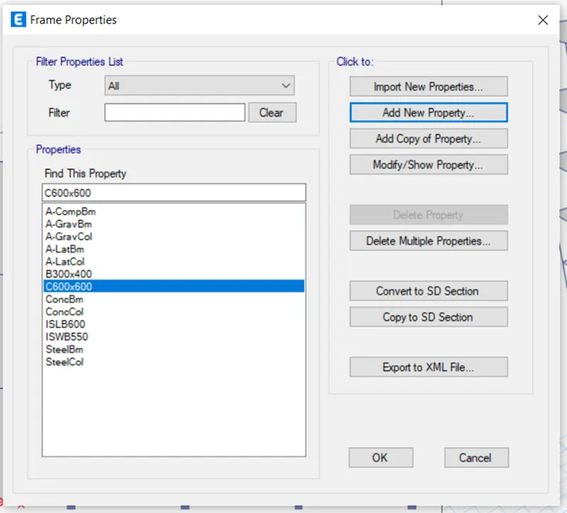
- Click Add New property to create another column type C400x400.
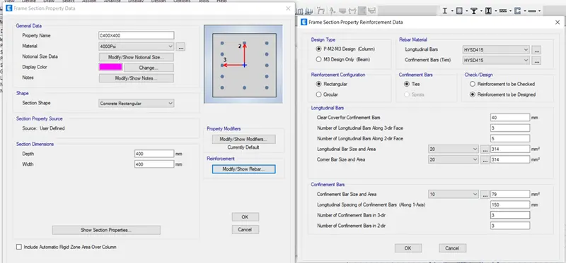
- Changing top 5 floors column size:
- Click Set display option, uncheck Beams and Floors option.
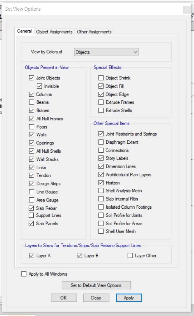
-
- Click ok.
- Only column is visible.
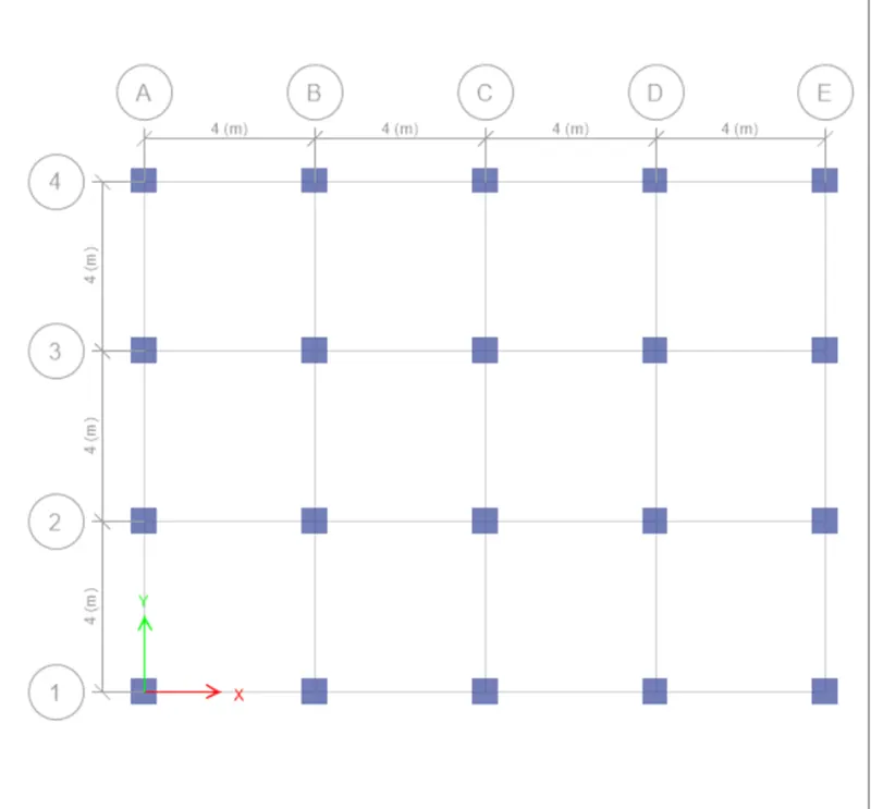
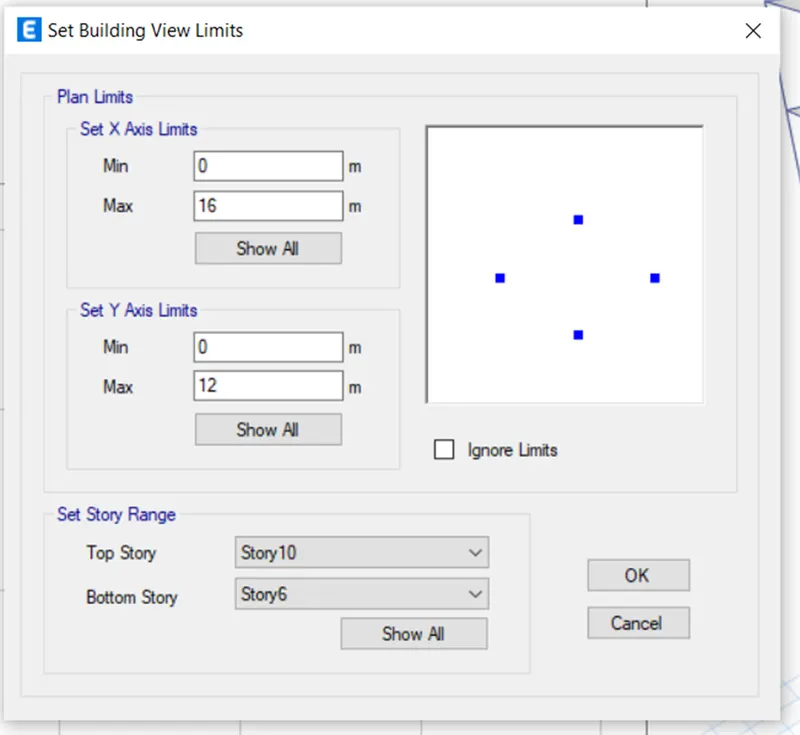
- Go to View -> Set building view limits
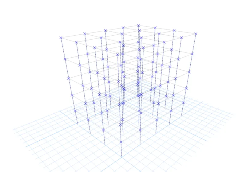
- Go to 3d view and select all columns.
- Go to Assign -> Frame -> Section property
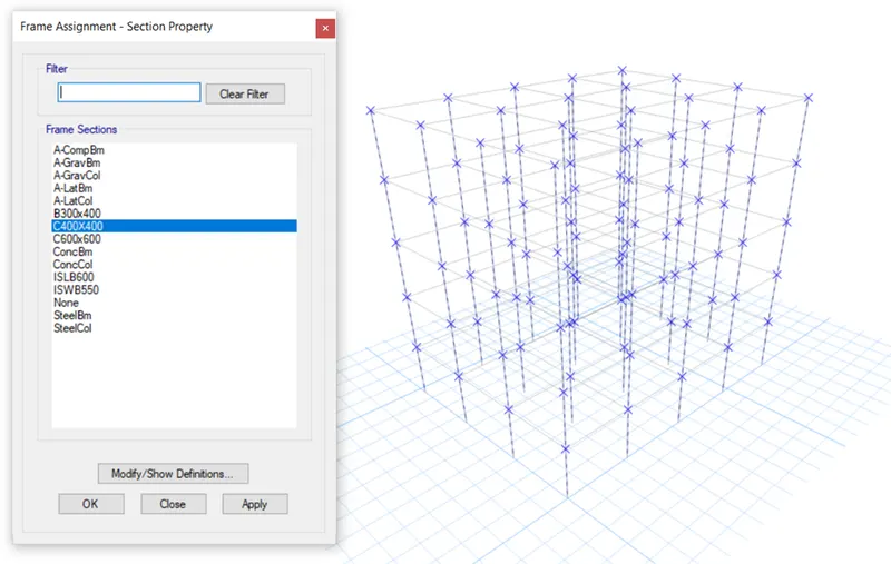
- Top 5 floor columns are changed to C400X400.
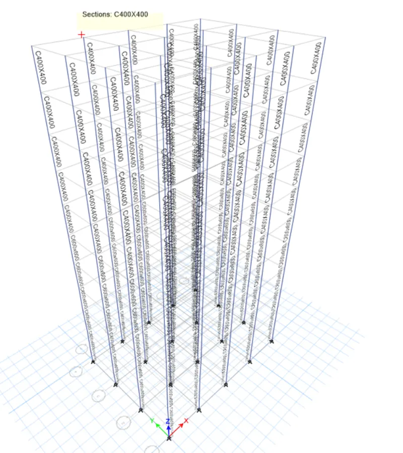
- Make Beams and floors visible again.
- Select the slab and assign it to diaphragm.
- Analysis:
- Click run analysis icon.
- Model F:
- Save as:
- Click File -> Save the file