Project 1 _Creating an Architectural plan for the provided plot size and develop relevant basic structural drawings
Aim: to draw the architectural drawing of a residential building with floor plan,elevations and sections.Draw the structural drawing including column,beam and footing plan.
Procedure: Open Auto CAD and set the limits.Set the units to metric as the plot is in meters.
1. Architectural drawing
a) Plan:
- Give the size of the plot using the rectangle command and offset for the thickness of the wall.
- Give the orientation of the plot by marking the east direction.
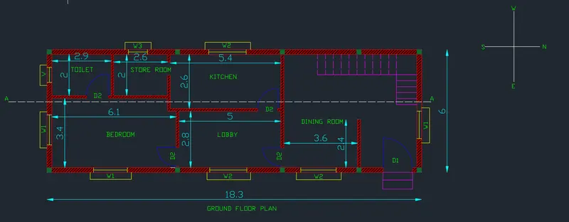
- Now we draw the ground floor plan.
- Using offset command draw the bedroom of size 3.4X6.1m.
- Then for the toilet offset 2m in vertical direction and 2.9m in horizontal direction.
- For the store room offset 2m in vertical direction and 2.6m in horizontal direction.
- For the lobby offset 2.8m in vertical direction and 5m in horizontal direction.
- For kitchen offseth 2.6m in vertical direction and 5.4m in horizontal direction.
- Now draw the stairs from north of dining roomand 1m for the offset of the width of stair.
- Stair dimension thread-0.25m,riser-0.17m and and width-1m number of steps 16.
- Draw 5 steps in the first flight offseting 0.25m and draw a landing of 1m width.
- For the next 3nd flight steps again offset 0.25m and draw 11 steps.
- Now draw the dining room by offseting 3.6m in horizontal direction and 2.4m in vertical direction.
- Now insert the text using multiline text with text height as 0.10m style as standard.
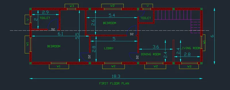
- Now we draw the first floor plan:
- Copy the ground floor plan and we make few changes.
- The kitchen is replaced with bedroom with same size of the bedroom-2.6X5.4m and a bathroom is attached with it.
- In the North-east direction living room is created of size 2.4mX2.8m by offseting in horizontal and vertical direction.
- Now we create the doors and windows and making them as block.
- Assume door sizes as: D1-1X2.1m and D2-0.90X2.1m
- Place the doors wherever opening is provided and mark them as D1 or D2 wherever required.
- Assume the size of windows as- W1-1X1.2m and W2-1.5X1.5m and ventilator as-0.50X0.50m.
- Place the windows and ventilators in the required place.
- Mark them as W1,W2,V and make them in a block.
- Now insert the dimensions using "DIMLINEAR" command and for repeated dimensioning use "DIMCONTINUE" and give text height as 0.25.
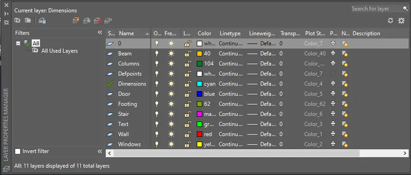
- Now create the layers using layer properties.
- Assign different colours to each layer in order to distinguish it.
- Insert respective elements in the layer.
- Insert steps in front of the entrance with riser as 0.15m and thread as 0.30m.
- Now we do the hatching so that objects show their material property.
- Hatch the brick wall and terrace using ANS 132 and scale 2.
b) Elevation:
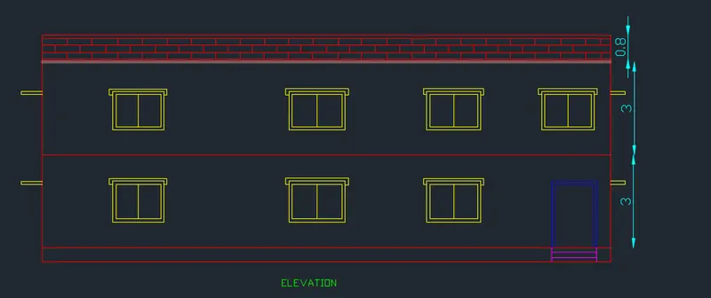
- Now project the lines to draw the elevation.
- Project the wall line to the top and draw an horizontal line.
- Offset 0.40m for the plinth level and 3m for the first floor level and 3m again for second floor.
- We draw the doors and windows from the plan and give height of 1.2m and 1.5m as required.
- Project the shades and draw the shades at top of window level.
- Trim off the extra lines using trim command.
- Offset 0.10m for thickness of doors and windows.
- Copy the windows and doors to other side also and draw the sunshade also.
- Project 0.80m to top to show the parapet wall.
- Create hatches for architectural purposes.
c) Section:
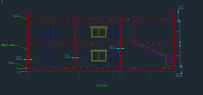
- Draw the section of ground floor plan.
- Project the line from the elevation for the height and from the section line of plan for the horizontal members.
- Draw the windows and door which we see after cutting the section line.
- To draw the section of stairs draw the 1st flight by offseting 0.175m for rise.
- Then for second flight we will show the side view riser as 0.175m and thread 0.25m leading to slab.
- Now we draw section of first floor:
- Section floor is drawn by projecting the plan and elevation.
- Draw the section of doors,windows,ventilators where the section line cuts it.
- Draw the doors and windows visible from viewing from the section line and also the parapet wall at the top.
- Now we draw the section of columns of column size 0.23mX0.23m.
- Place the columns in all the corners and intersections of walls and place it in layer.
- Copy the same for the first floor plan.
- In the section,project the column from the plan to the section.
- Mark the ground and plinth level.
- Hatch the brick wall with ANS 132 scale 0.01
- Hatch the slab thickness with AR conc for concrete.
- Using the leader command insert the text marking R.C.C,brickwall and P.C.C etc. and give dimensions.
2. Structural drawing
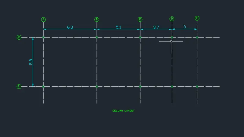
a) Column layout:
- We consider column of size of 0.23X0.23m.
- Columns are placed in all corners of the wall and intersection of walls wherever required.
- Copy the plan with column and delete all the windows.
- Draw the grid lines for column from the annonate tab-centre line with a scale of 0.03.
- Delete all the walls and stairs.
- Now make the grid lines as 1,2 in the y direction and A,B,C,D,E,F in the x direction.
- Create a circle and insert text into it.
- Do the dimensioning between grid lines.
b) Beam layout:
i) Plinth beam layout:
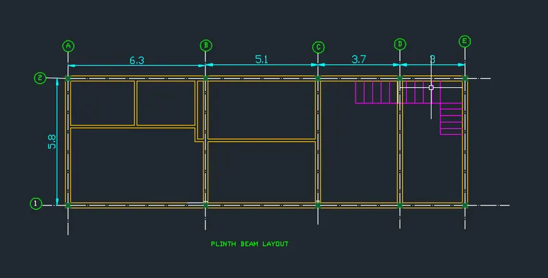
- For drawing plinth beam layout copy the grounf floor plan with column.
- Plinth beam is provided below all the walls.
- First connect columns by beam of width 0.23m which are the primary beams.
- Now we draw the plinth-secondary beam and connect internak walls as beams of width 0.12m,beam to beam connections are secondary beams.
- Delete all the walls.
ii) Beam layout for first floor:
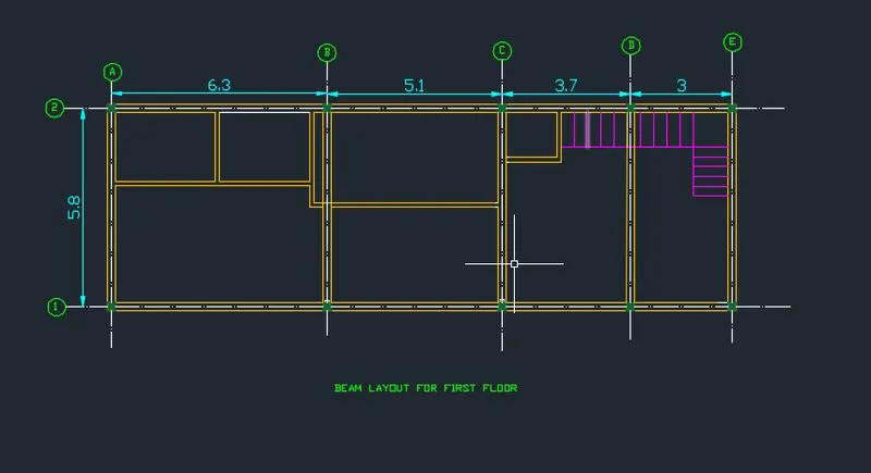
- Now we draw primary beams of top floor.
- Copy the first floor plan with column.
- Draw beam of width 0.23m connecting all the columns.
- Now draw secondary beams of top floor:
- For other walls beam of size 0.12m is provided at bottom portion of first floor slab.
C) Footing plan layout:
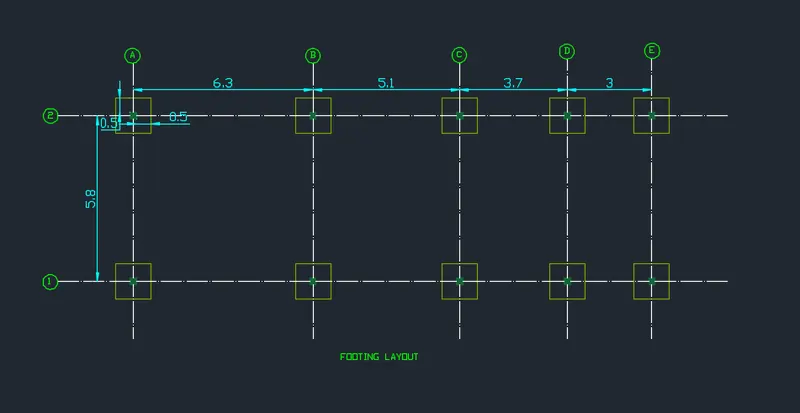
- Isolated footing of size 1mX1m is provided.
- Create a rectangle with dimension 1mX1m and place the centre of rectangle with the centre of column.
- Make a layer for footing and place the footings in that layer.
- Dimension the distance between footing and column.
Result: Architectural and structural plan of a two storeyed residential buidling is drawn.