Project 1_Comparative study of different storey buildings for Seismic forces
AIM :
To model and analyze multiple buildings with different floor levels and design parameters using Etabs software and compare the results to understand their overall seismic behavior.
INTRODUCTION :
ETAB or ETABS they mean the same. Its full form is extended three-dimentional analysis of building system. It is an engineering software product that caters to multi-story building analysis and design. ETABS offers a single user interface to perfom modelling, analysis, design and reporting.There is no limit to the number of modelling windows,model manipulation views and data views .
OBJECTIVES :
- Know how to extract different seismic responses for a structure
- How to easily alter certain properties in an ETABS model
- Know the factors influencing the dynamic characterastics of building
- Know the factors influencing the Natural Period of a building
- Know the factors influencing the Mode shape of oscillations
1. BUILDING - A
PROCEDURE :
- Open ETABS software
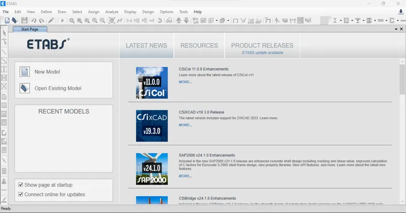
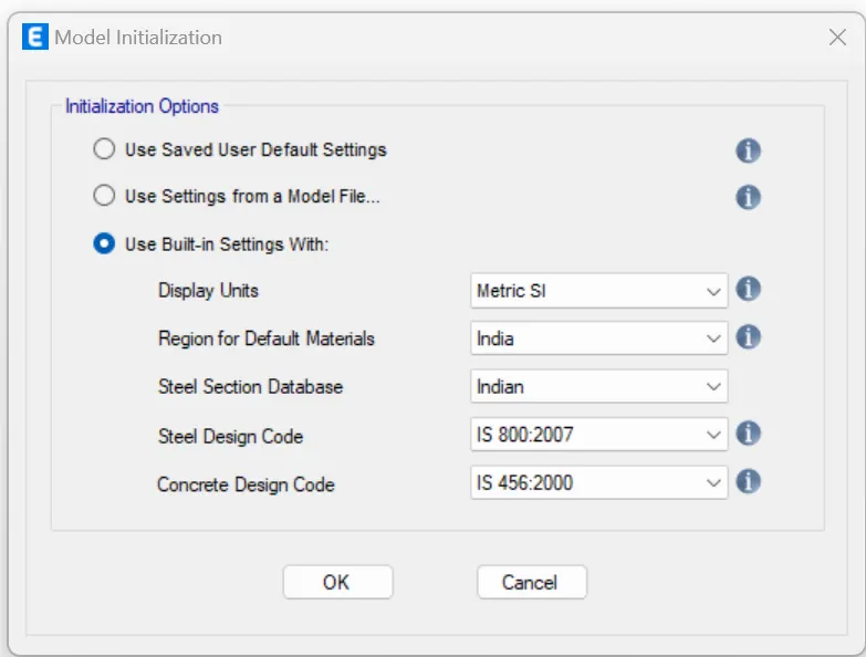
- Then click on the new model and choose use built-in setting with option
- Set the display unit as Metric SI or as per the requirement
- Then click ok
- New dialogue box will appear.
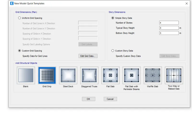
- Select the custom grid spacing and then select the edit grid data
- New dialoge box will appear and enter the X grid data at a distance of 4 meter and Y grid data at 4 meter distance
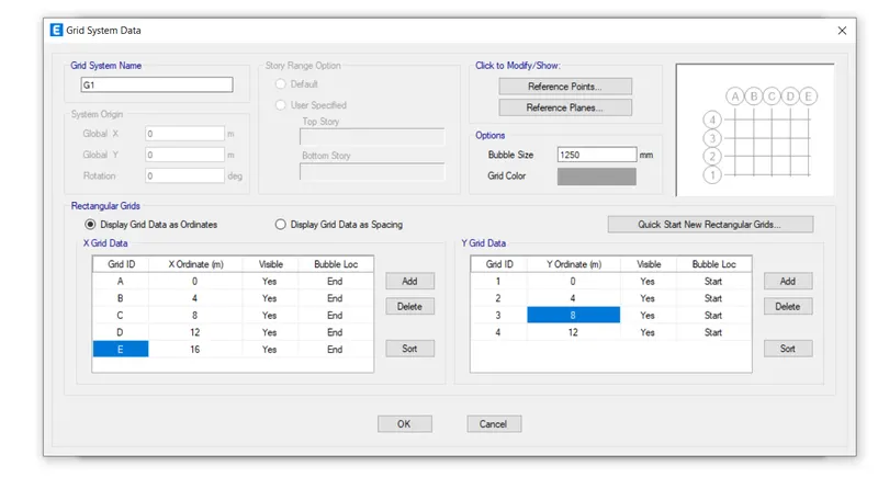
- click ok
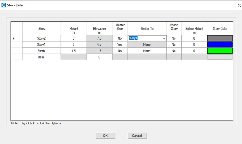
- Then select custom story data and select edit the story data
- Then make story1 as master story and all other storys are similar to 1
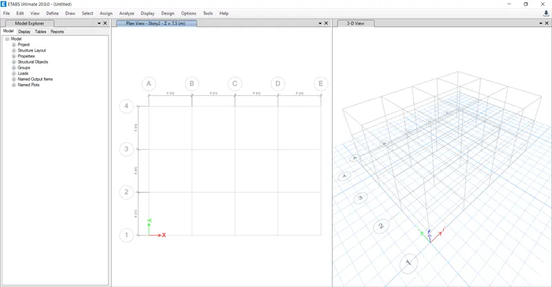
- Then our building model is generated in the window
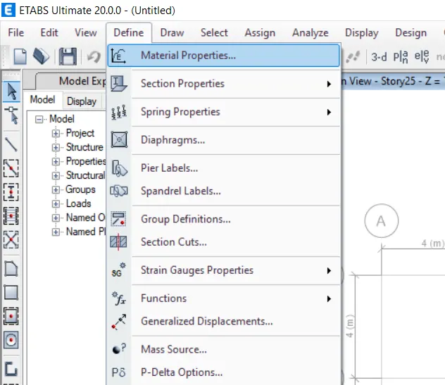
- To provide material properties select define from that select material properties
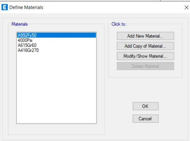
- New window will appear and from that select add new material
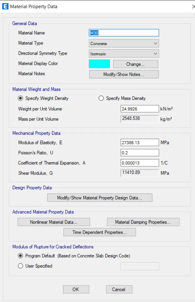
- New window will appear now define material type as concrete and grade as M30
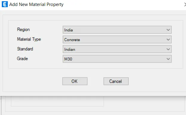
- New window will appear now define material type as concrete and grade as M30
-
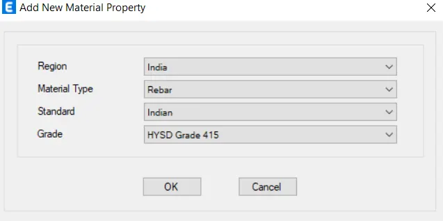
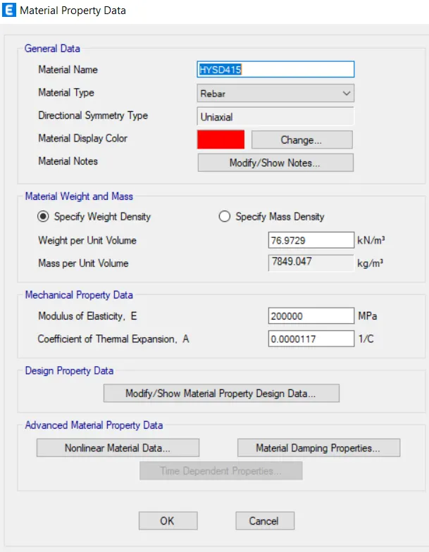
- Similarly define rebar property
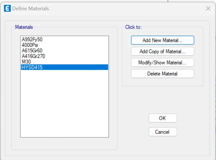
- Go to the define tab ,select section properties and from that select frame properties
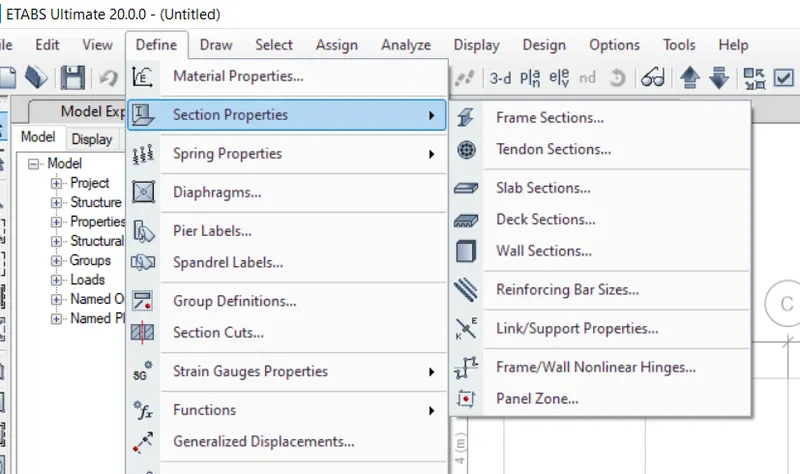
- A new window will appear ,in that select add new property
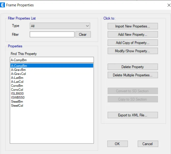
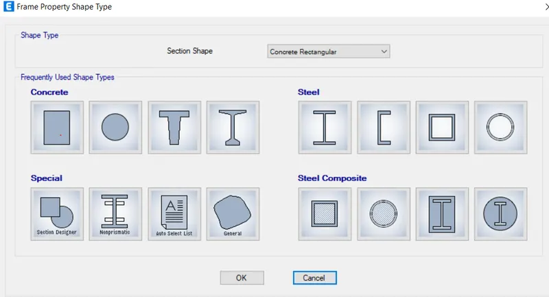
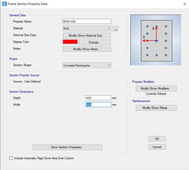
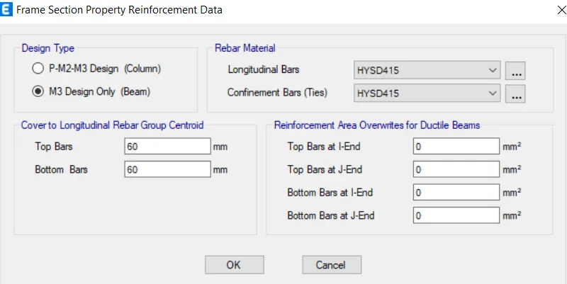
- Then select the rectangular concrete section,rename it as B300*400
- Change the property as M30 and change the size as B300*400
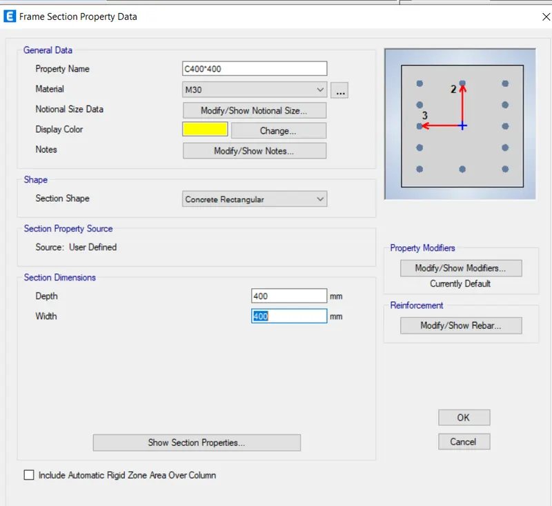
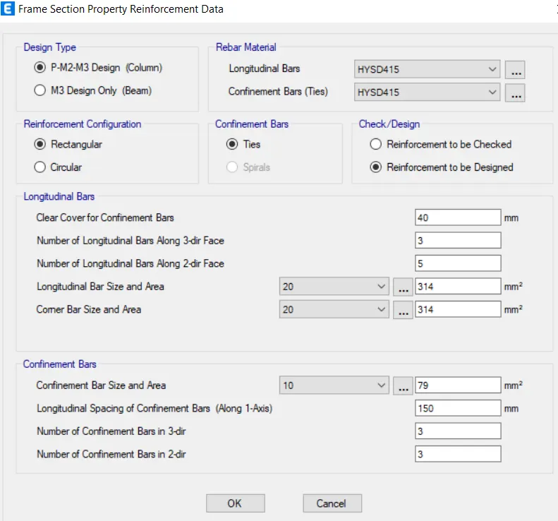
- Similarly add column section properties
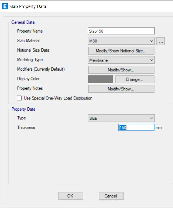
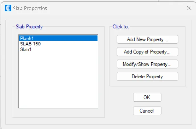
- Then go to define select section properties from that select slab section
- New window appears
- Rename it as SLAB150, modelling type as membrane and change thickness as 150mm
- Draw structural members
- For that first select the mode as all stories at the right bottom corner
- Then select quick draw columns and change property as C400*400
- Place the columns at every intersections of grid
- Then select quick draw columns and change property as C800*800
- Place the columns at every intersections of grids
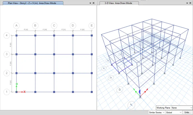
- Then select quick draw beams/columns
- Change the property as B300*400
- place beam at all grids
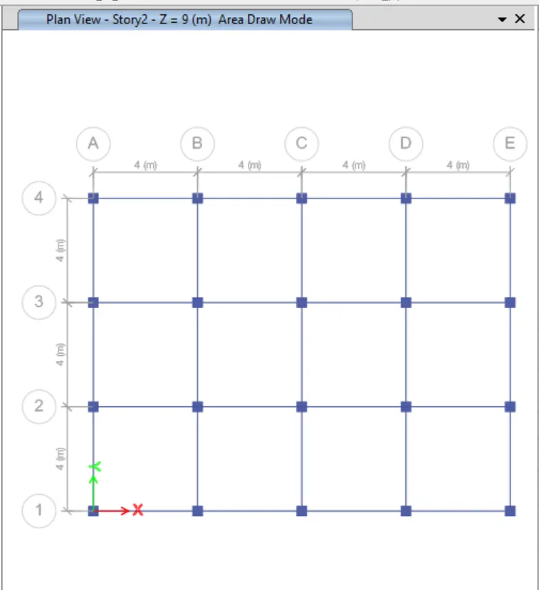
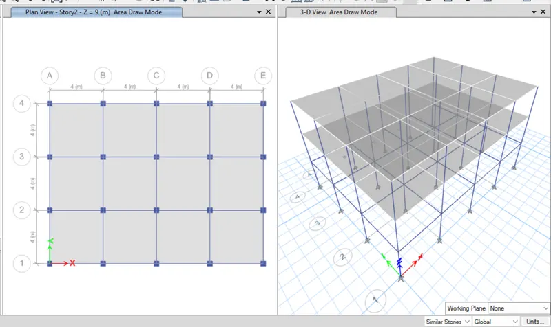
- Now we need to change mode as similar stories at the bottom of the window
- In order to avoid slab placement in the plinth level
- Select quick draw floor/slab and draw slab sections
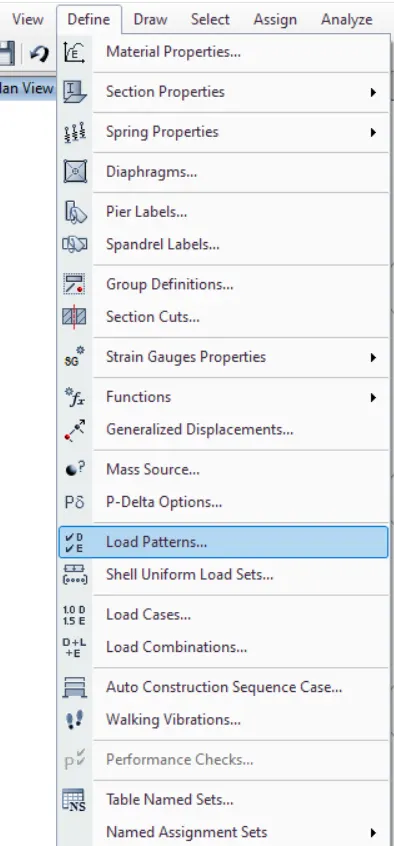
- Click on the define and from that select the load patterns
- Define the loads like dead load , live load , brick wall load and earthquake load in x direction and eccentric earthquake loads in positive x and negative x and same loads in y direction also mension IS codes of respective loads
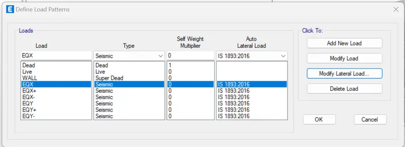
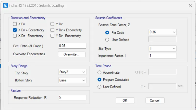
- Click on modify lateral load, set range from base to 25th story,change direction and eccentricity ,seismic zone factor as 1 and time period as 0.5 seconds
- Do the same for all the earthquake loads
- Now go to the mass source from the define tab
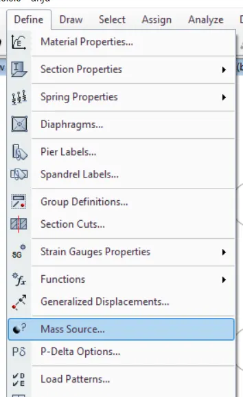
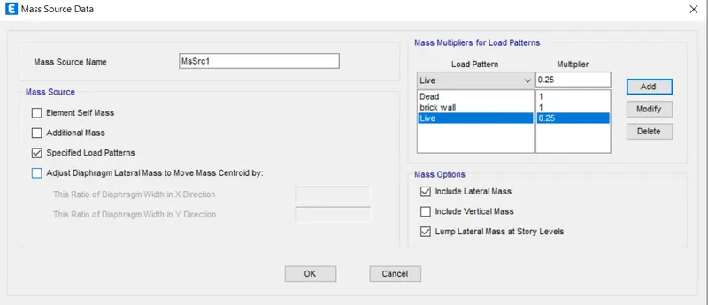
- modify the mass source and check the specify load pattern
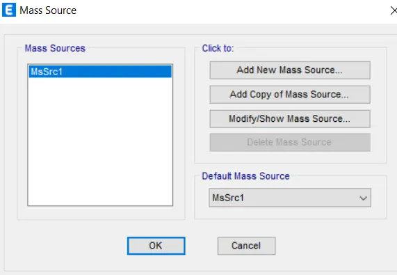
- Add load pattern and assign the model Then Click ok
- Define load cases
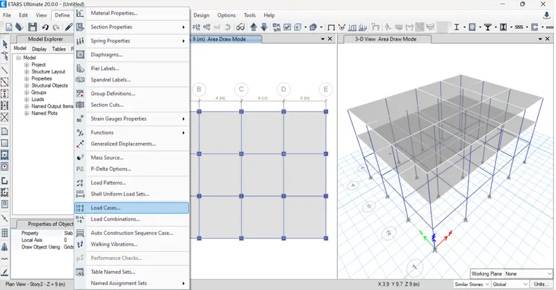
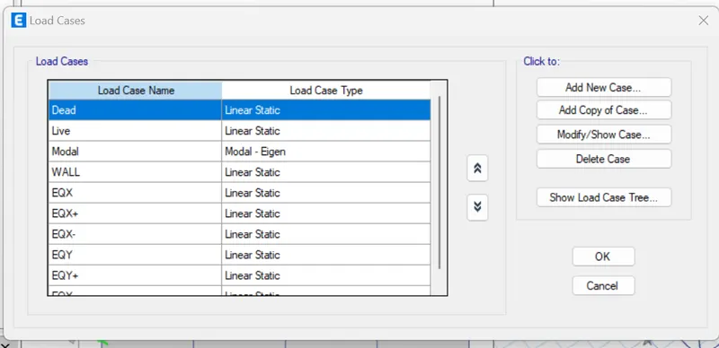
- click ok
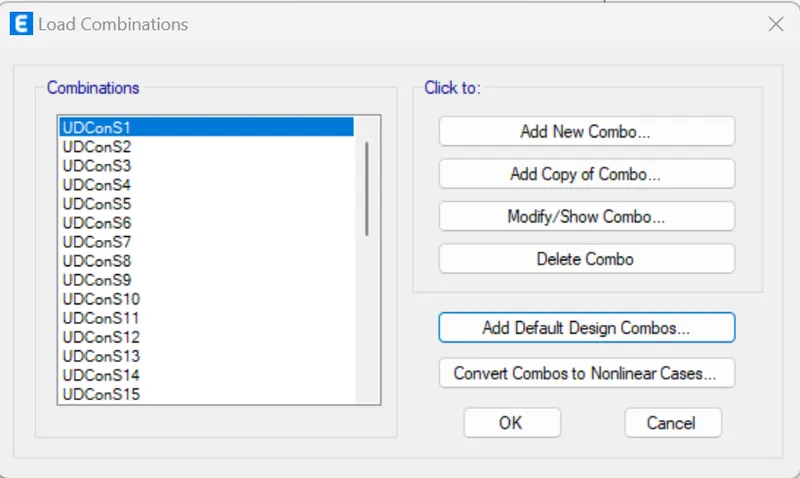
- Then go to define-->load combination
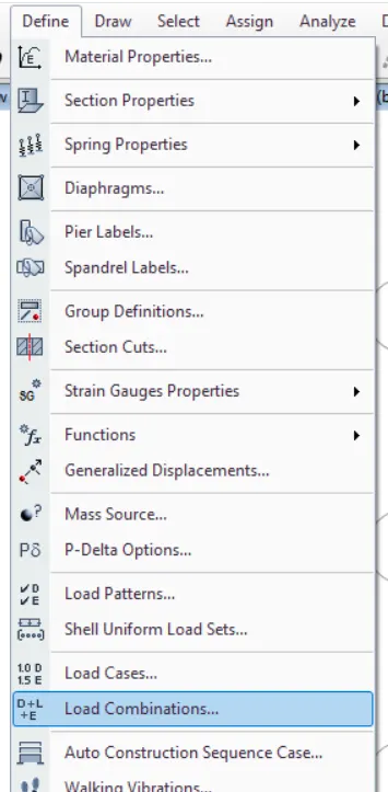
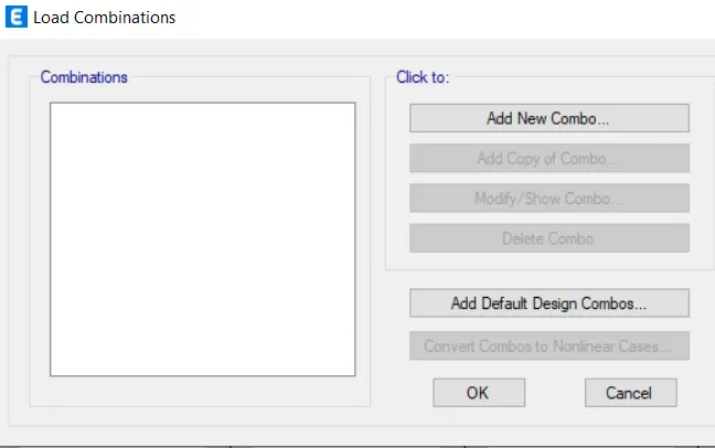
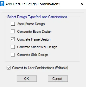
- Click on the add default design combos and select the concrete frame design then click ok
- Assign loads
- To assign loads , select the similar stories at the bottom of window
- Then select the members
- After that go to the assign tab-->shell loads -->uniform
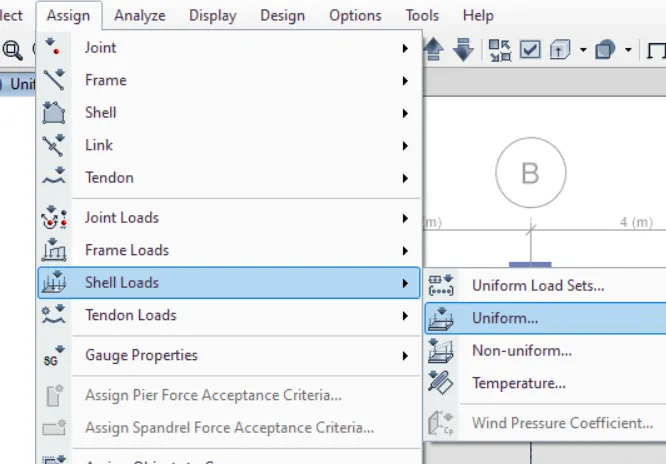
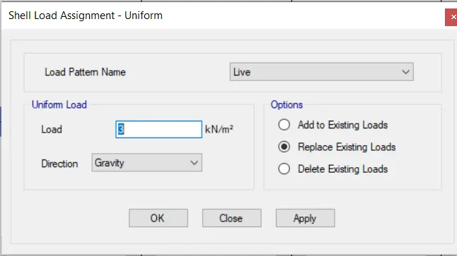
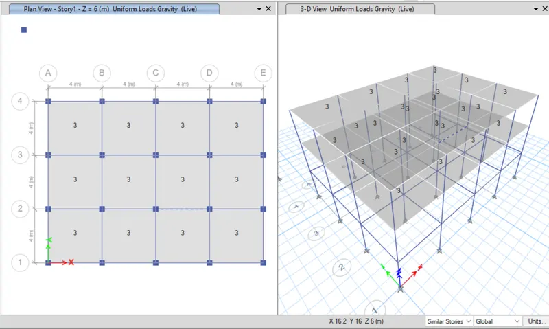
- A new window will appear in that select live load and give value as 3kN/m2
- Click on apply
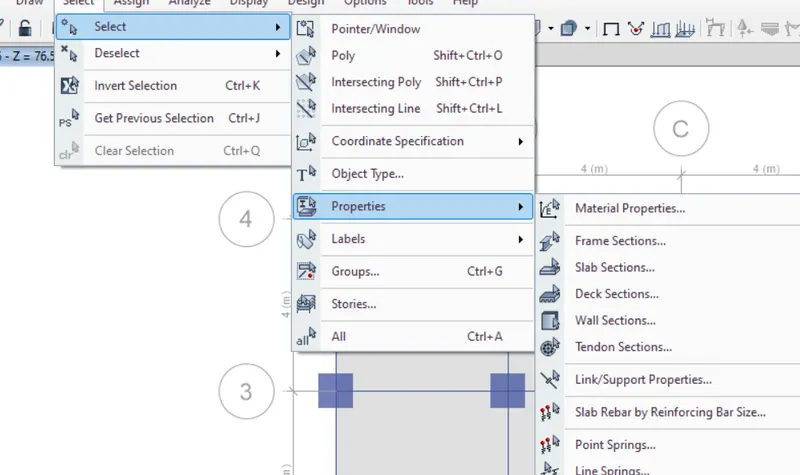
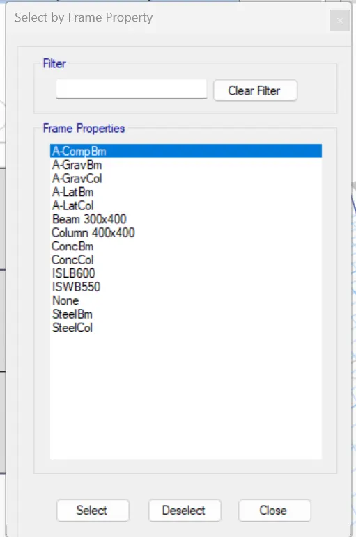
- Then select all story at the bottom of the window and select all beams by clicking object types-beams under select tab
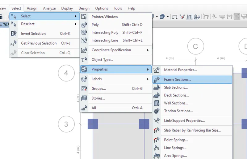
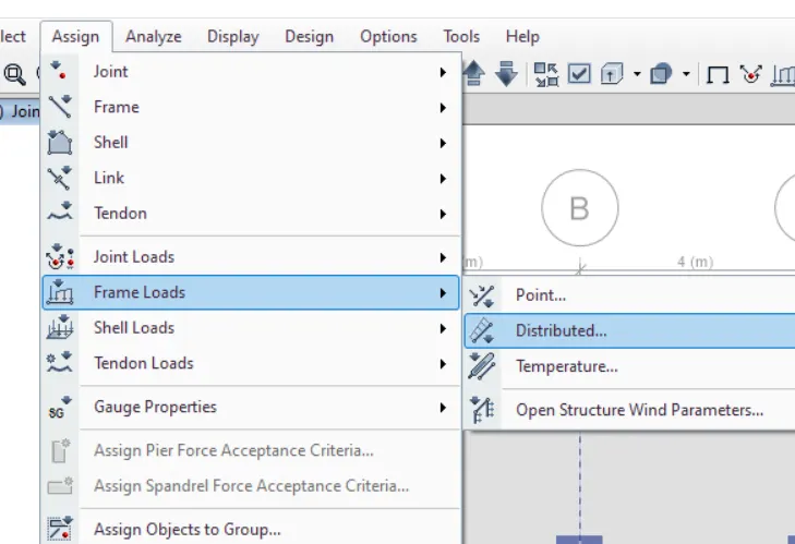
- After that do to the assign tab-->frame load-->distributed
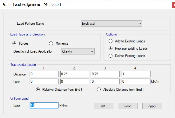
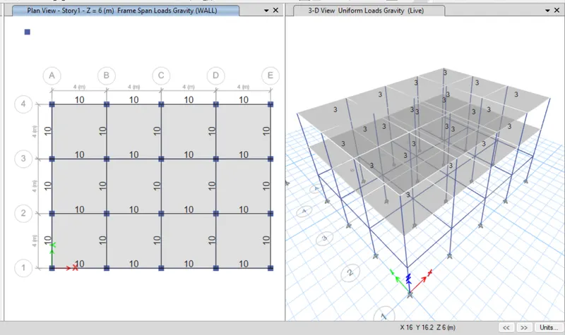
- Enter the value as 10kN/m2
- first select the slab
- then go to the assign tab,select shell and click on diaphragm created successfully
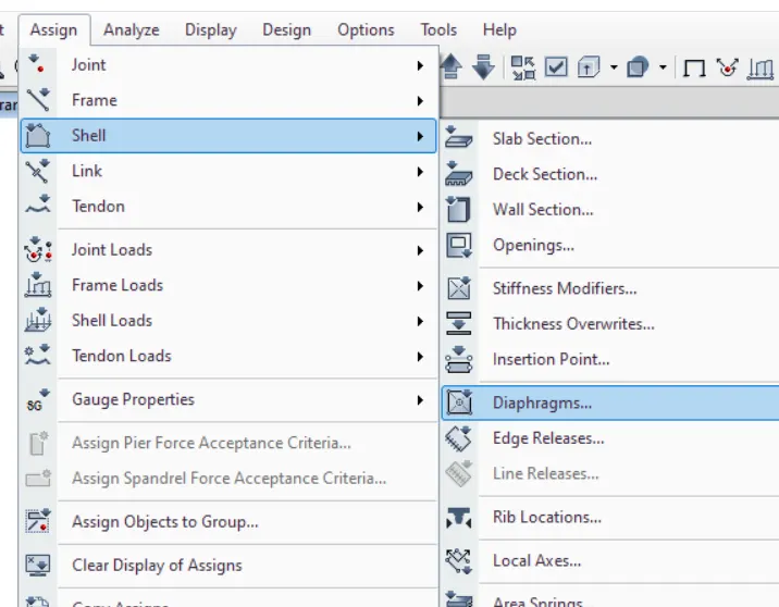
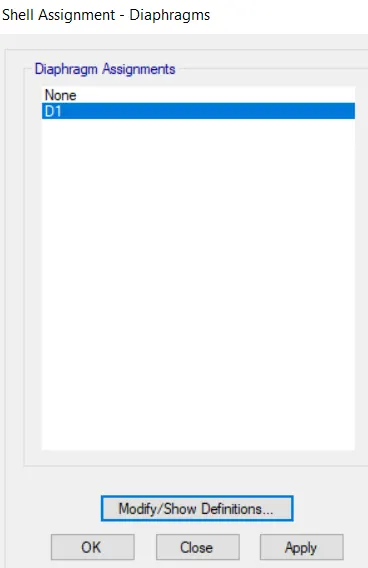
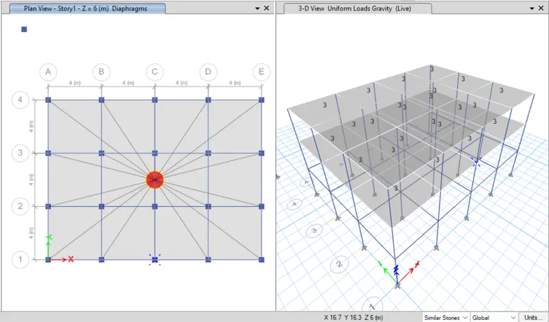
- check model the modelled structure is verified without warnings and errors

- Then go to the analyze tab abd run analysis
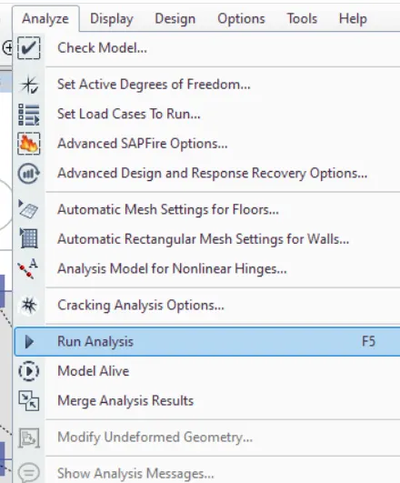
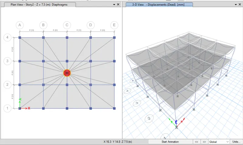
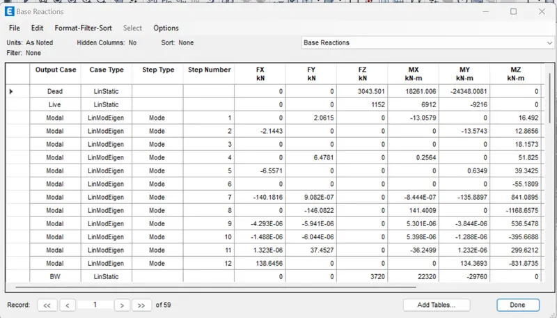
- Now click on Display-show tables analysis results structure output modal information-modal period and frequencies
- The time periods for fundamental mode-ly direction and fundamental mode -1 direction are noted from the table as follows
MODAL RESPONSE FOR BUILDING - A :
2. BUILDING -B(G+5)
- We will save a copy of building A file
- Mke the changes needed for building B
PROCEDURE :
- From model A go to the files and click on the save as option
- And name it as "BUILDING B"
- The model is set for changes as per the requirements of building B
- Go to edit-->story and grid data
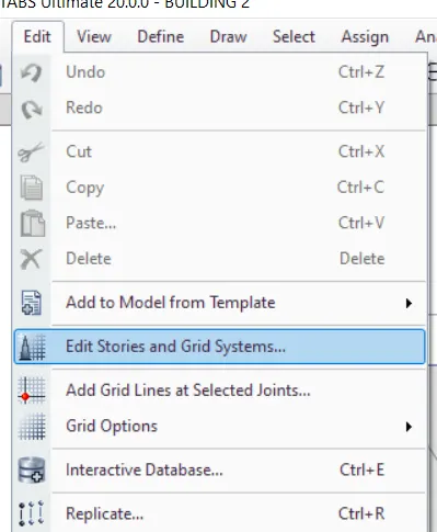
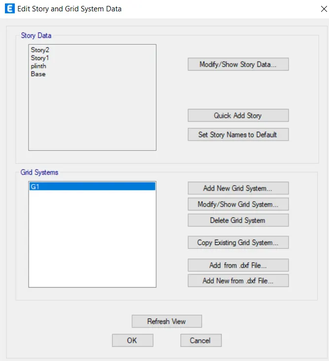
- Click on modify/show data option
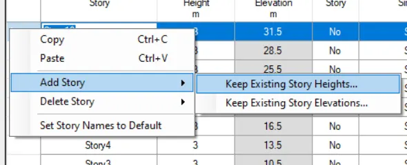
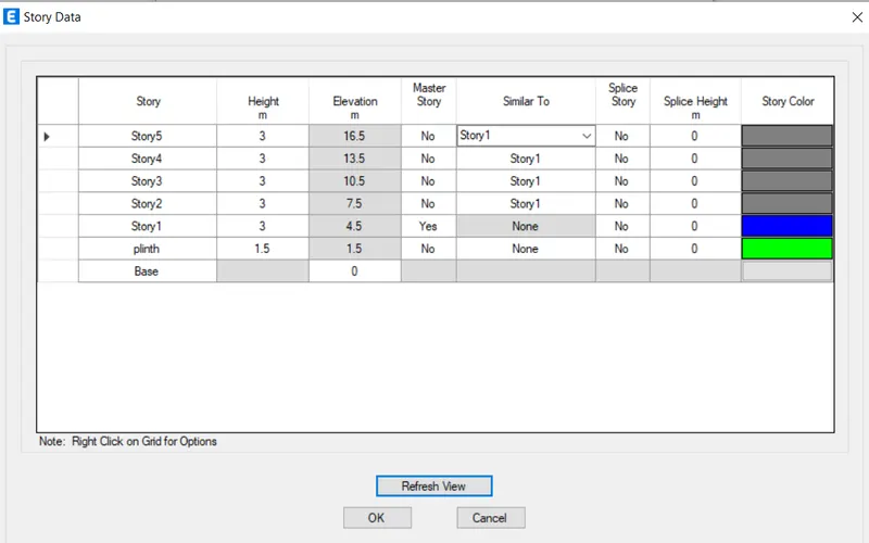
- From there add story and set the height
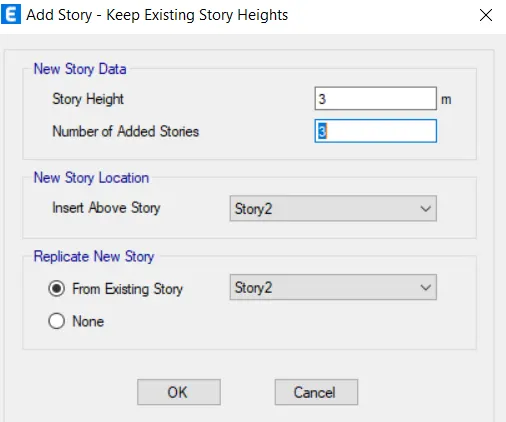
- Click ok
Check the model before running analysis :
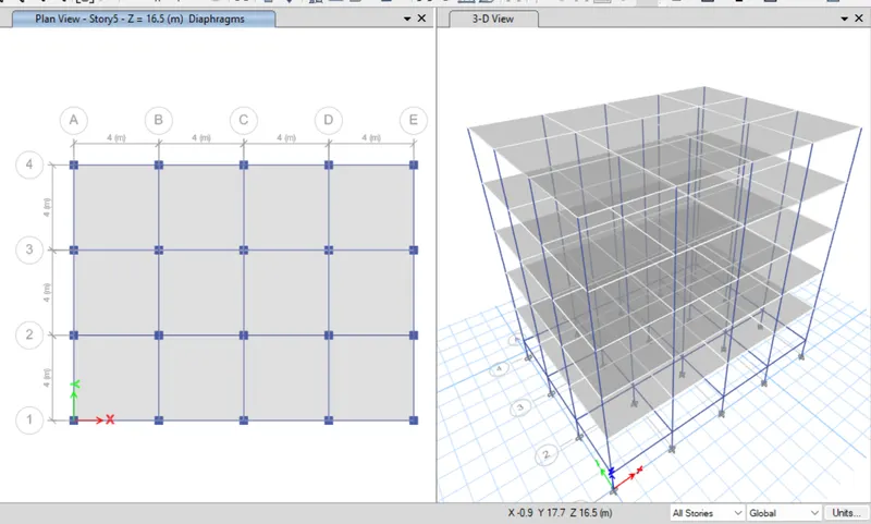
- Now our model is ready so, we need to check for two or three things before running the analysis and noting the model period
- First check is for load assignment
- Need to check for shell loads and frame loads
- Similarly ,you need to check if the diaphragm has been assigned to a new model or not
- If the diaphragm is not visible,you need to select all the floors and assign the daiphragm like we did for the first model
CHECK FOR SHELL LOADS :
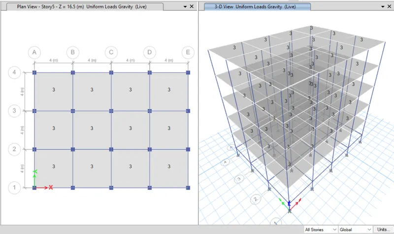
CHECK FOR FRAME LOADS :
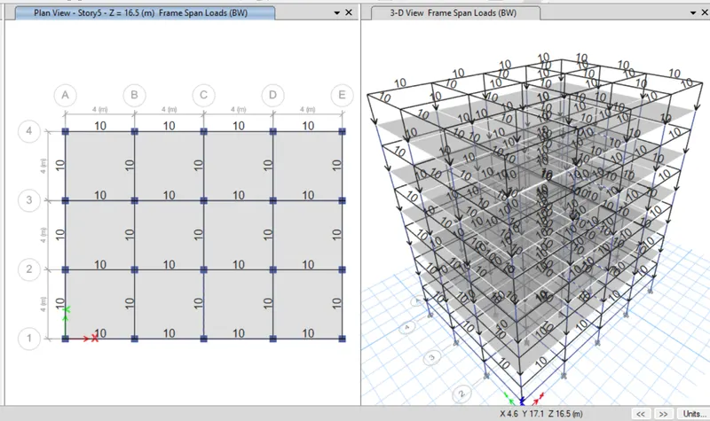
DIAPHRAGM CHECK
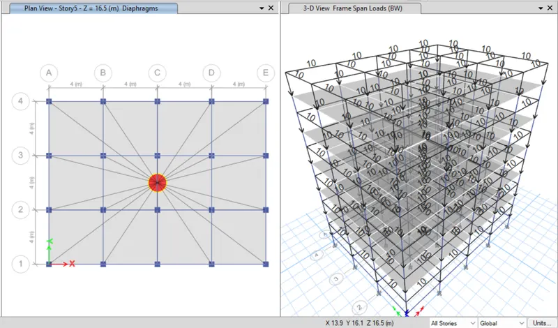
RUN ANALYSIS
- Then go to the analyze tab abd run analysis
- It will take few seconds and the deflected shape of the building will appear indicating that the analysis has been completed
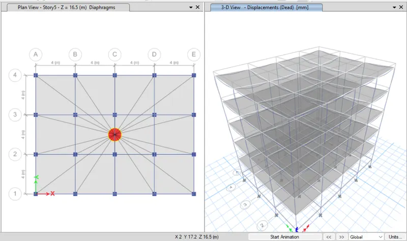
MODAL RESPONSE FOR BUILDING B
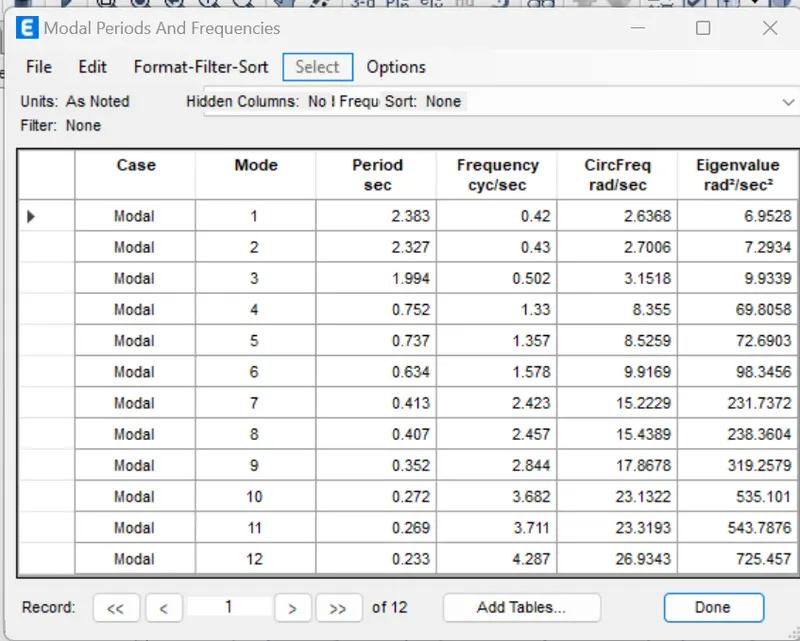
3. BUILDING C (G+5 with column orientation in X-direction)
- The storey and grid data for the building c will remain same
- But we need to change the column size and orient the same in x- direction
- From BUILGING B go to the files and click on the save as option
- And name it as "BUILDING C"
- The model is set for changes as per the requirements of building C
EDIT COLUMN SIZE AND ORIENTATION
- To edit the colum section go to define-->section properties-->frame section
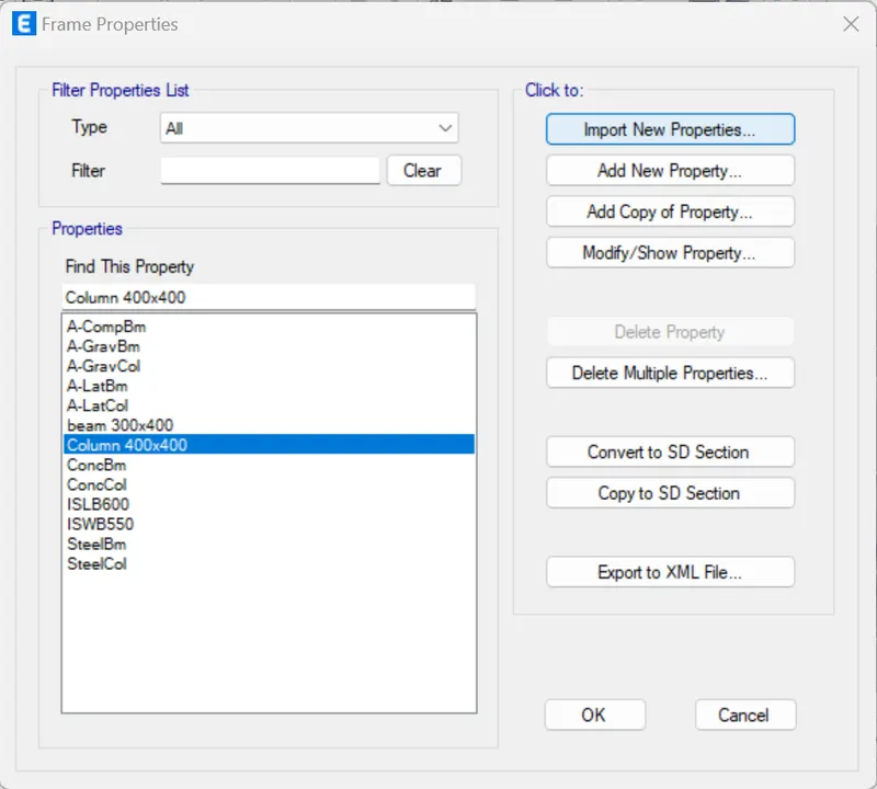
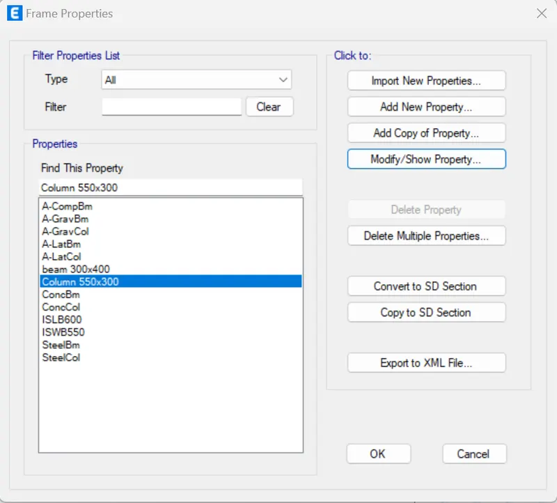
- Select the previously created column
- Click on the modify/show properties option
- Rename the column as C550*300
- Then we need to orient the 550mm in the X-direction
- Select the column section then go to assign-->local axis-->rotate-->90 degree
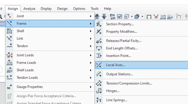
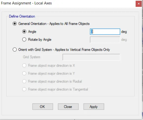
- All the column shall be oriented in the X-direction
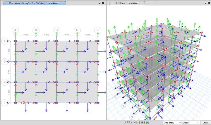
Check the model before running analysis
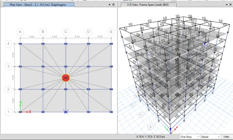
- Now our model is ready so, we need to check for two or three things before running the analysis and noting the model period
- First check is for load assignment
- Need to check for shell loads and frame loads
- Similarly ,you need to check if the diaphragm has been assigned to a new model or not
- If the diaphragm is not visible,you need to select all the floors and assign the daiphragm like we did for the first model
CHECK FOR SHELL LOADS :
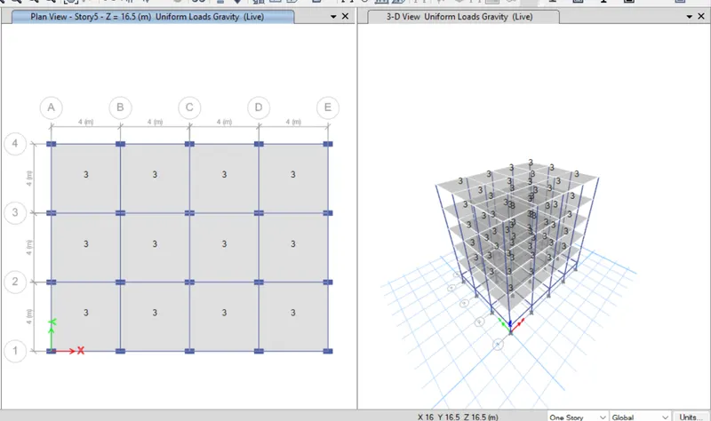
CHECK FOR FRAME LOADS :
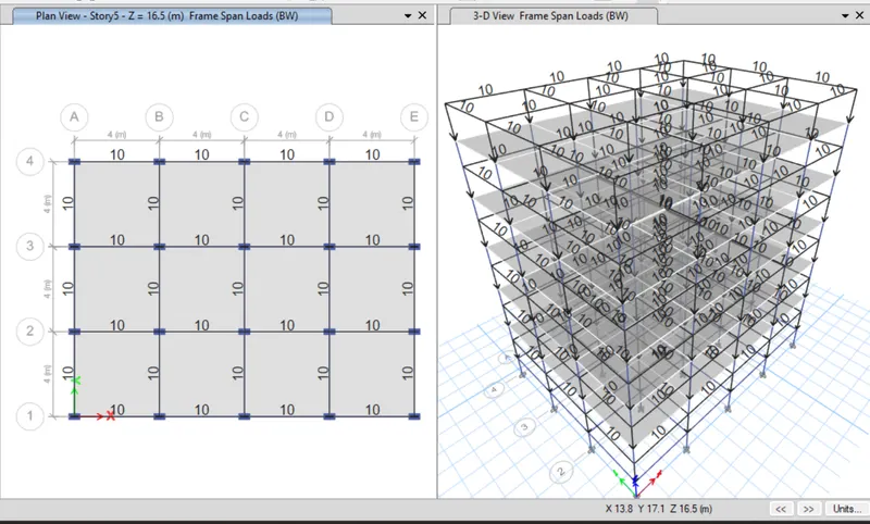
DIAPHRAGM CHECK :
RUN ANALYSIS
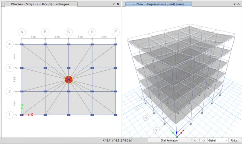
- Then go to the analyze tab abd run analysis
- It will take few seconds and the deflected shape of the building will appear indicating that the analysis has been completed
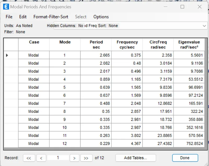
MODAL RESPONSE FOR BUILDING C :
4. BUILDING D (G+5 with column orientation in Y-direction)
- The storey and grid data for the building c will remain same
- But we need to change the column size and orient the same in Y- direction
- From BUILGING C go to the files and click on the save as option
- And name it as "BUILDING D"
- The model is set for changes as per the requirements of building D
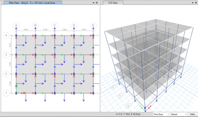
Select the column section and bring the orientation back to zero
- Select the column section then go to assign-->local axis-->rotate-->0 degree
Check the model before running analysis
- Now our model is ready so, we need to check for two or three things before running the analysis and noting the model period
- First check is for load assignment
- Need to check for shell loads and frame loads
- Similarly ,you need to check if the diaphragm has been assigned to a new model or not
- If the diaphragm is not visible,you need to select all the floors and assign the daiphragm like we did for the first model
CHECK FOR SHELL LOADS :
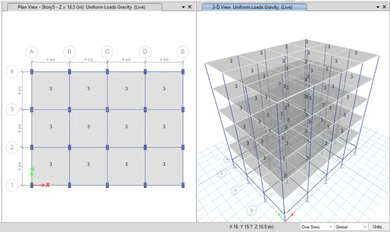
CHECK FOR FRAME LOADS :
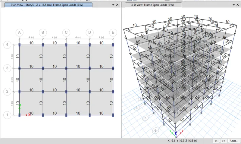
DIAPHRAGM CHECK :
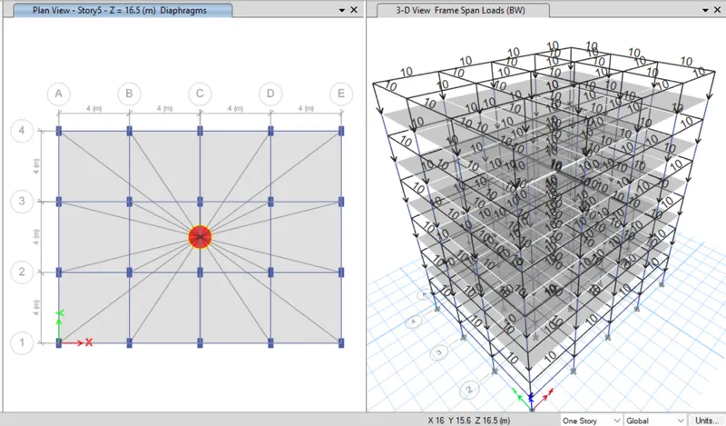
RUN ANALYSIS
- Then go to the analyze tab abd run analysis
- It will take few seconds and the deflected shape of the building will appear indicating that the analysis has been completed
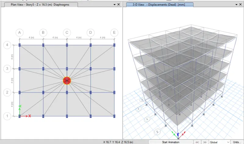
MODAL RESPONSE FOR BUILDING D
5. BUILDING E (G+10)
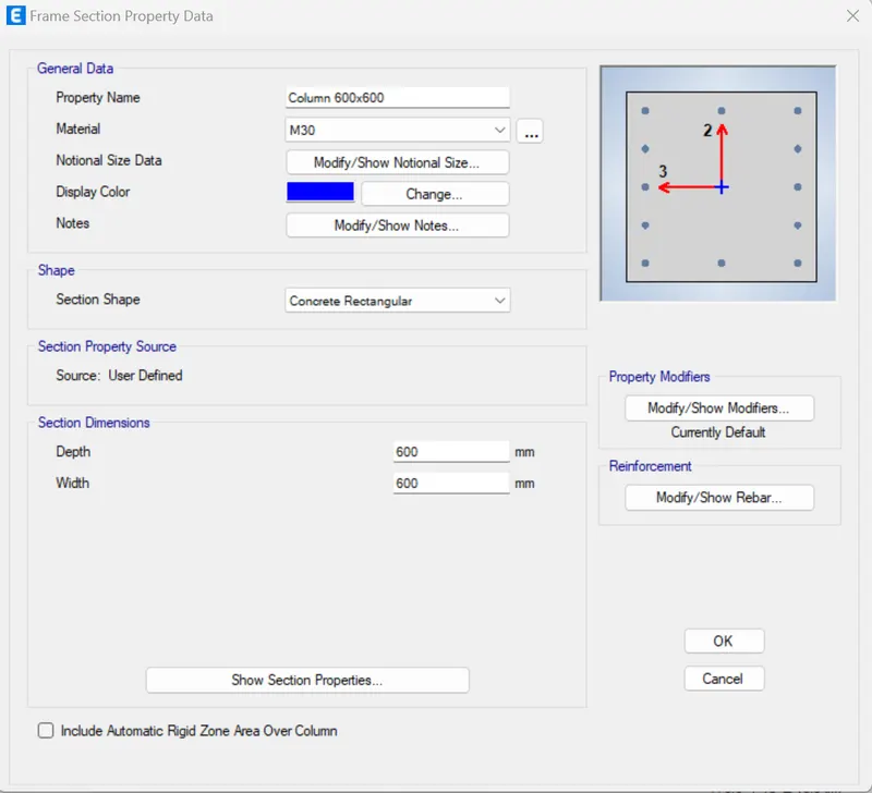
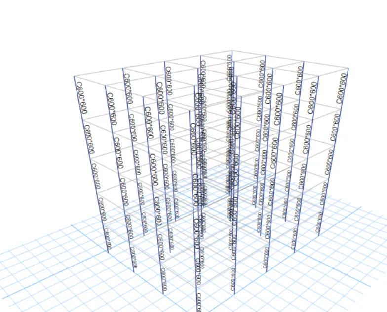
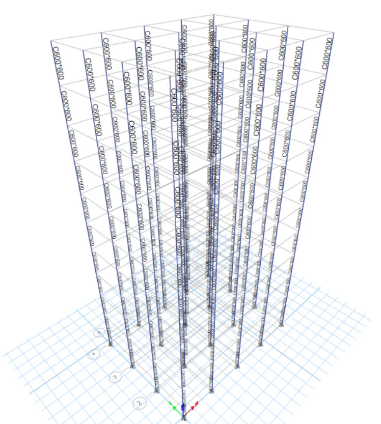
- In this model , we need to add 5 storey to our model,we also need to assign different column sizes to different floors
- Column sizes for top 5 storeys:400*400
- Column sizes for bottom 5 storeys 600*600
STEP:1
- From BUILDING D go to the files and click on the save as option
- And name it as "BUILDING E"
- The model is set for changes as per the requirements of building E
STEP:2
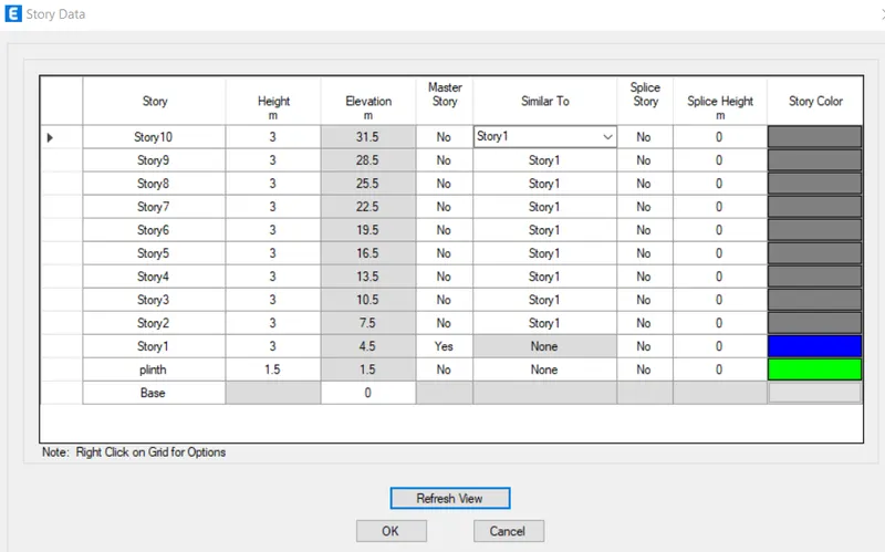
EDIT STORY DATA
- Go to edit-->story and grid data
- Click on modify/show data option
- From there add story and set the height
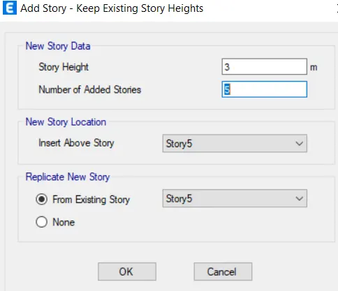
- Click ok
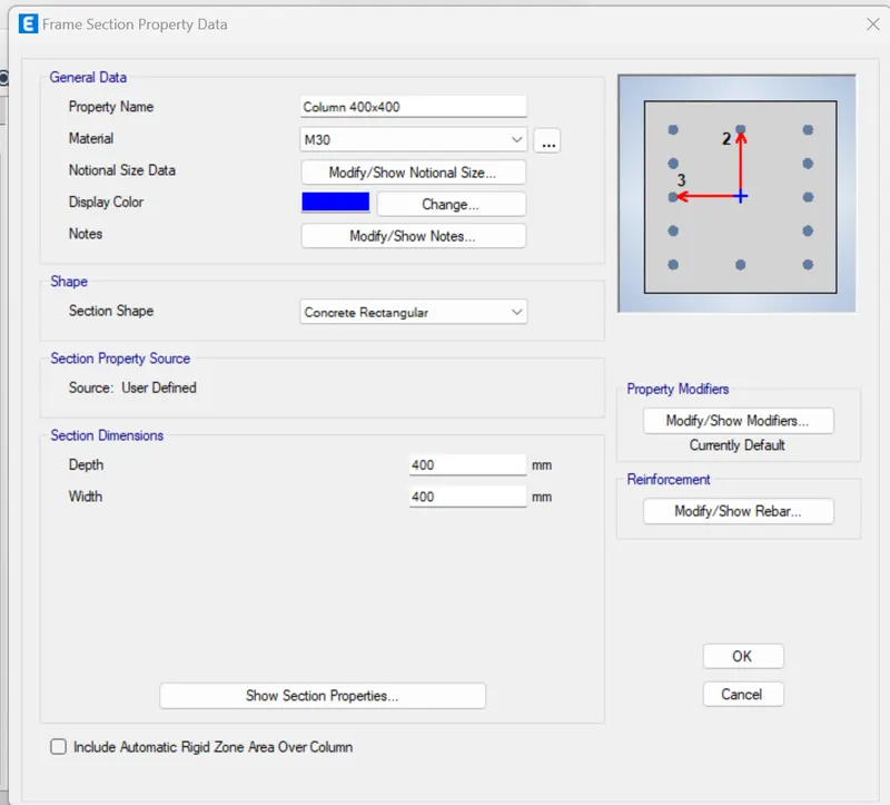
Change the view settings of the model
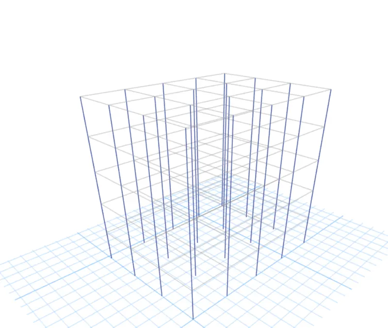
- Using the view option settings , we can uncheck the structural members that you want to hide from the current modelling purpose
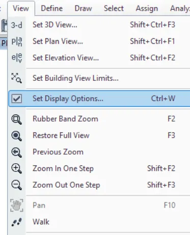
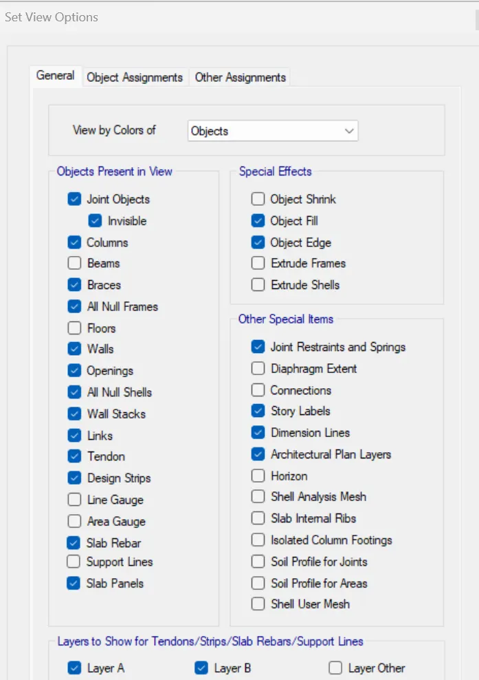
- From this uncheck beams and floors and click ok
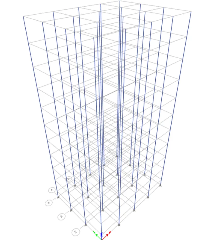
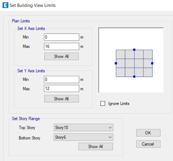
Set the building limit, select columns and assign them
- Column size is different for top 5 story and bottom 5 story
- So we can go to edit -->set building limits
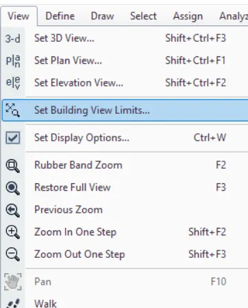
- Building limit option allows you to view only the floors that ypu need to work
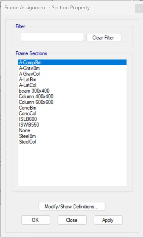
- Hence, first set the limit to bottom 5-->select all columns --> go to assign and assign them as the required column section
CHECK FOR SHELL LOADS :
CHECK FOR FRAME LOADS :
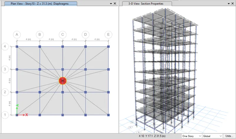
DIAPHRAGM CHECK :
RUN ANALYSIS
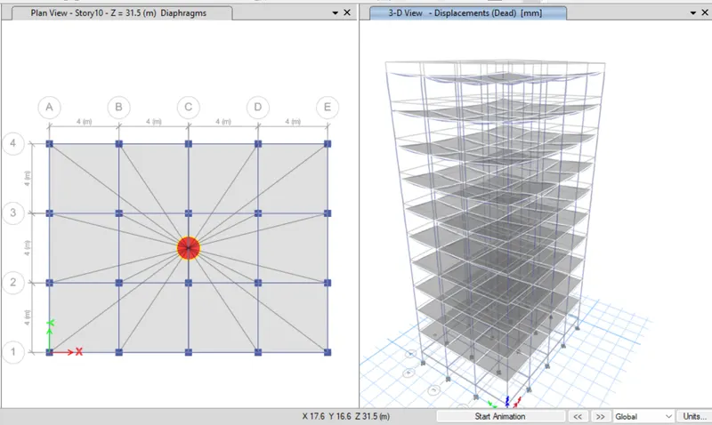
- Then go to the analyze tab abd run analysis
- It will take few seconds and the deflected shape of the building will appear indicating that the analysis has been completed
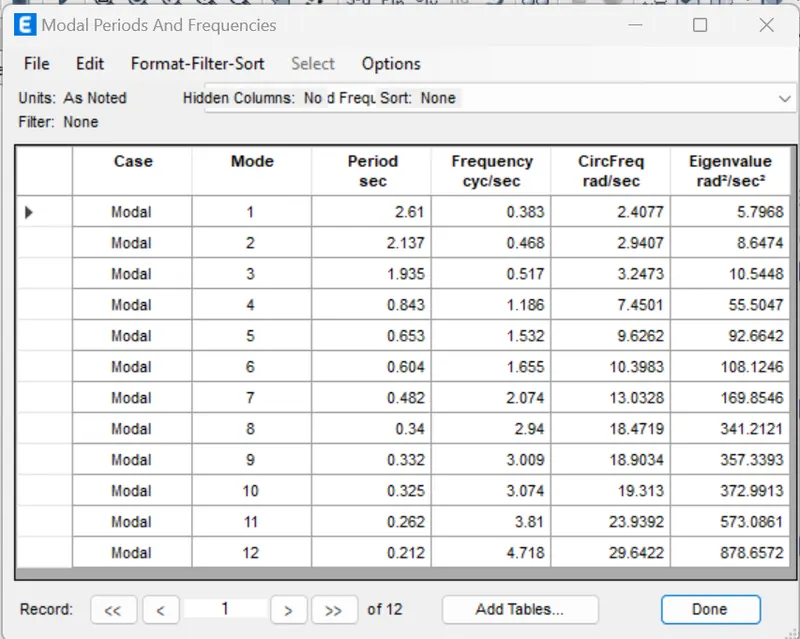
MODAL RESPONSE FOR BUILDING E
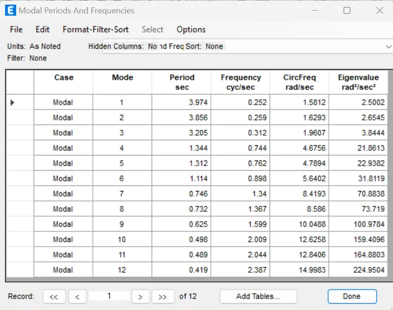
6. BUILDING F (G+10)
Consistent column size throughout the structure
STEP:1
- From BUILDING Ego to the files and click on the save as option
- And name it as "BUILDING F"
- The model is set for changes as per the requirements of building F
STEP:2
Change the view settings of the model
- Using the view option settings , we can uncheck the structural members that you want to hide from the current modelling purpose
- From this uncheck beams and floors and click ok
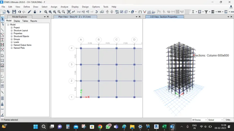
- Select all the columns
- Assign C600*600
CHECK FOR SHELL LOADS :
CHECK FOR FRAME LOADS :
DIAPHRAGM CHECK :
RUN ANALYSIS
- Then go to the analyze tab abd run analysis
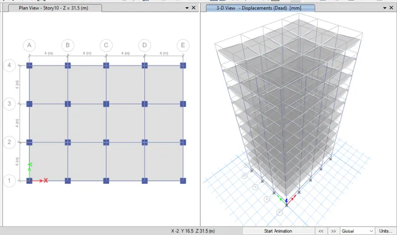
- It will take few seconds and the deflected shape of the building will appear indicating that the analysis has been completed
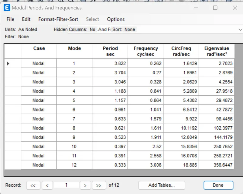
MODAL RESPONSE FOR BUILDING F
7. BUILDING G (G+25)
For this model , we need to add 15 new stories and assign different column sizes on different floors.We can follow the exact procedure that has already been explained for the previous project to create BUILDING F
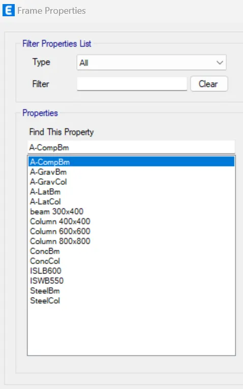
- Column for top 5 stories:C400*400
- Column for middle 10 stories : C600*600
- Column of bottom 10 stories :C800*800
- From BUILDING F go to the files and click on the save as option
- And name it as "BUILDING G"
- The model is set for changes as per the requirements of building
- Go to edit-->story and grid data
- Click on modify/show data option
- From there add story and set the height
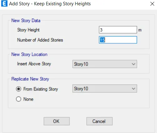
- Click ok
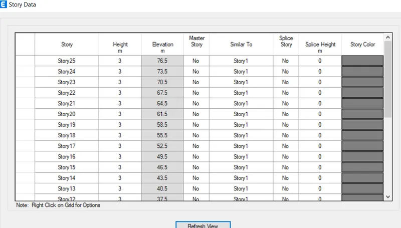
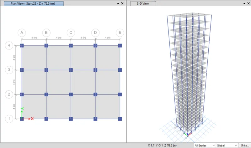
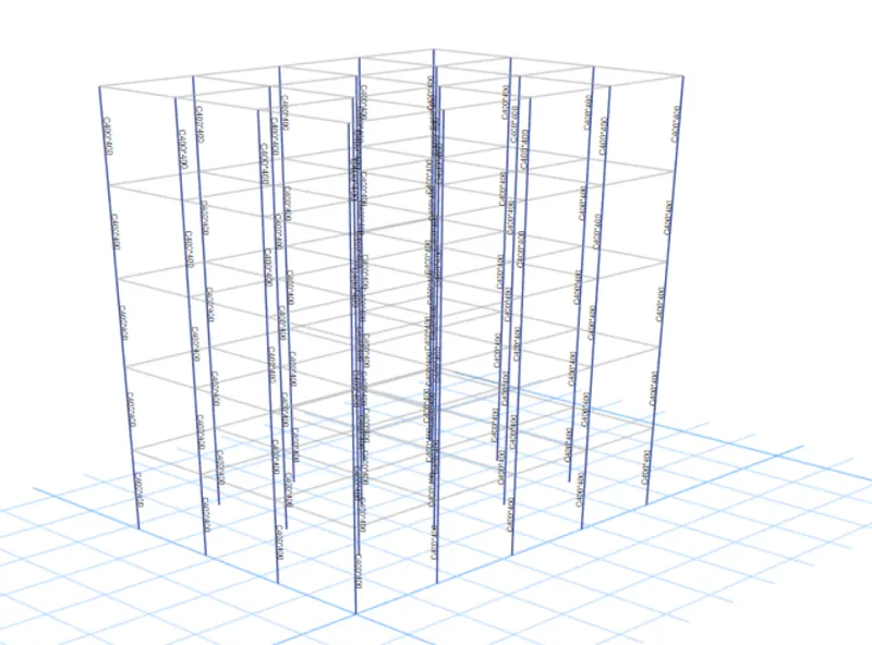
Change the view settings of the model
- Using the view option settings , we can uncheck the structural members that you want to hide from the current modelling purpose
- From this uncheck beams and floors and click ok
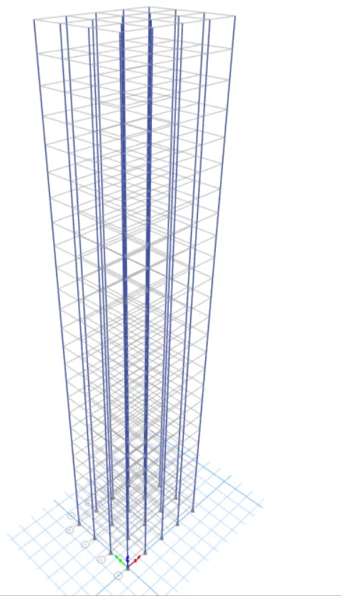
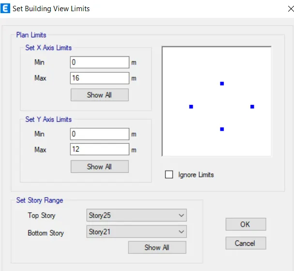
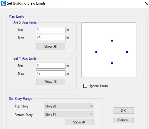
Set the building limit, select columns and assign them
- Column size is different for top 5 story and bottom 5 story
- So we can go to edit -->set building limits
- Building limit option allows you to view only the floors that you need to work
- Hence, first set the limit ,then select the column and assign the size of the column
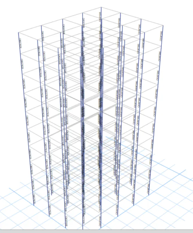
- Then go to define -->set building limit-->show all
CHECK FOR SHELL LOADS :
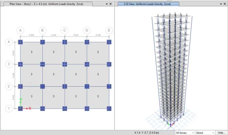
CHECK FOR FRAME LOADS :
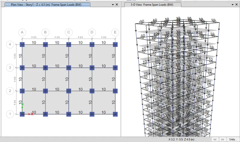
DIAPHRAGM CHECK :
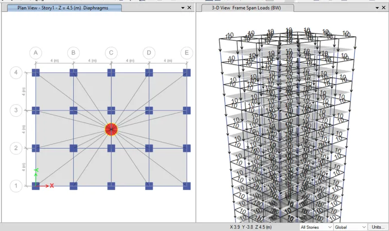
RUN ANALYSIS :
- Then go to the analyze tab abd run analysis
- It will take few seconds and the deflected shape of the building will appear indicating that the analysis has been completed
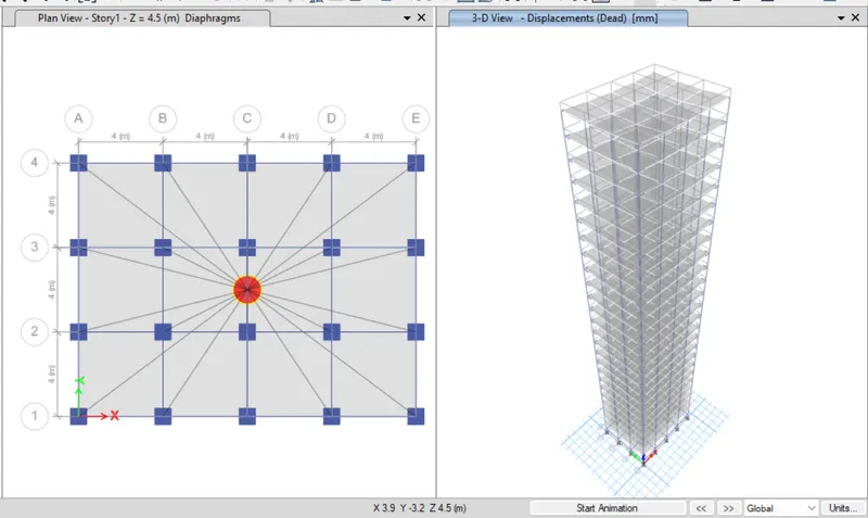
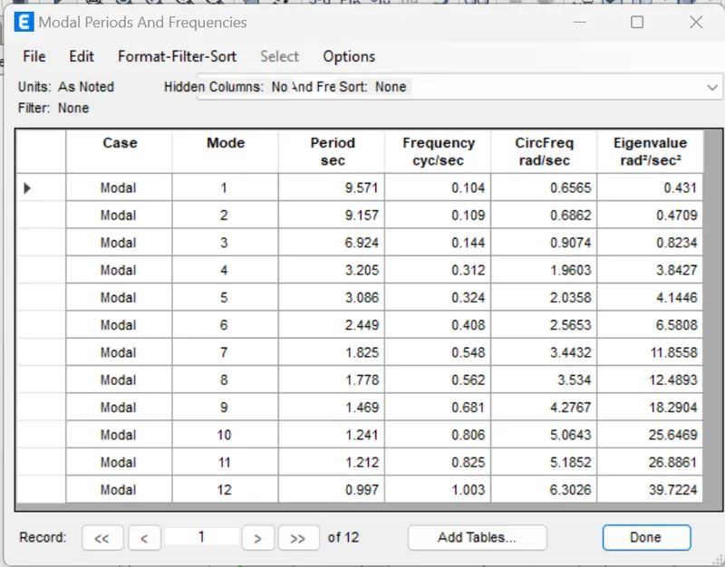
MODAL RESPONSE FOR BUILDING G :
8. BUILDING H ( G+25)
This is the same model as the previous one .All we need to do is to change the column size as C800*800
- From BUILDING G go to the files and click on the save as option
- And name it as "BUILDING H"
- The model is set for changes as per the requirements of building H
Change the view settings of the model
- Using the view option settings , we can uncheck the structural members that you want to hide from the current modelling purpose
- From this uncheck beams and floors and click ok
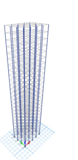
- Select all the columns and assign C800*800
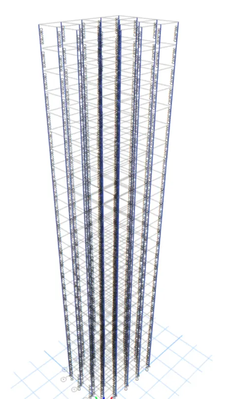
RUN ANALYSIS :
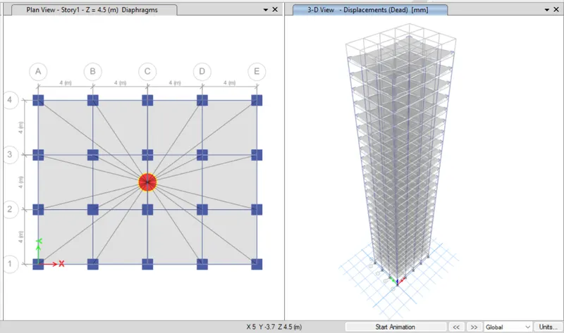
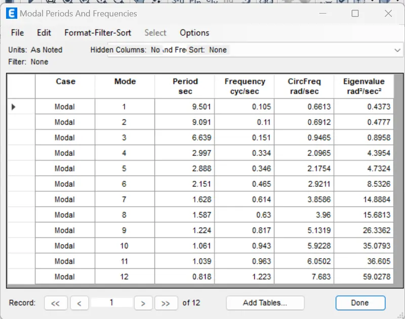
MODAL RESPONSE FOR BUILDING H
9. BUILDING J(G+25)
Building J is the exact copy of the BUILDING H , no need to alter anything related to the modelling .We need to increase the imposed load on the building by 10%
- From BUILDING G go to the files and click on the save as option
- And name it as "BUILDING J"
- The model is set for changes as per the requirements of building J
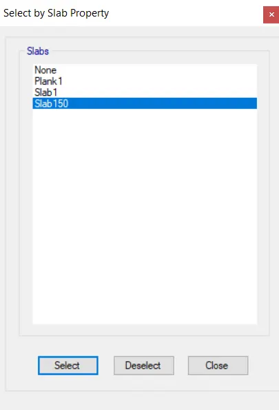
- Select the slab 150 slab section
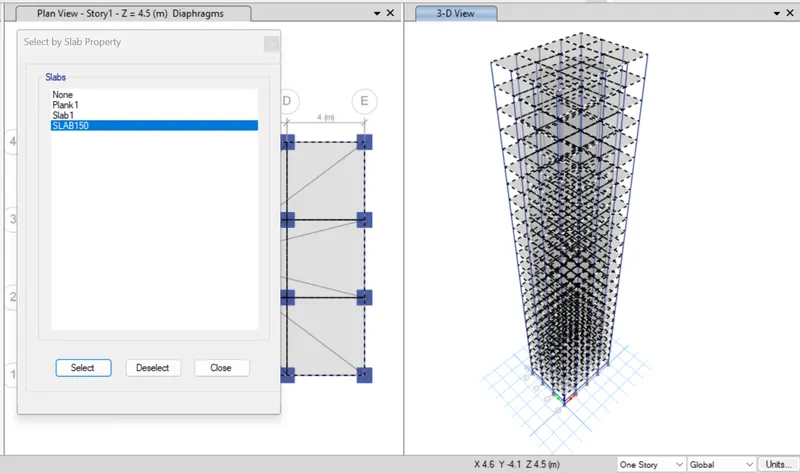
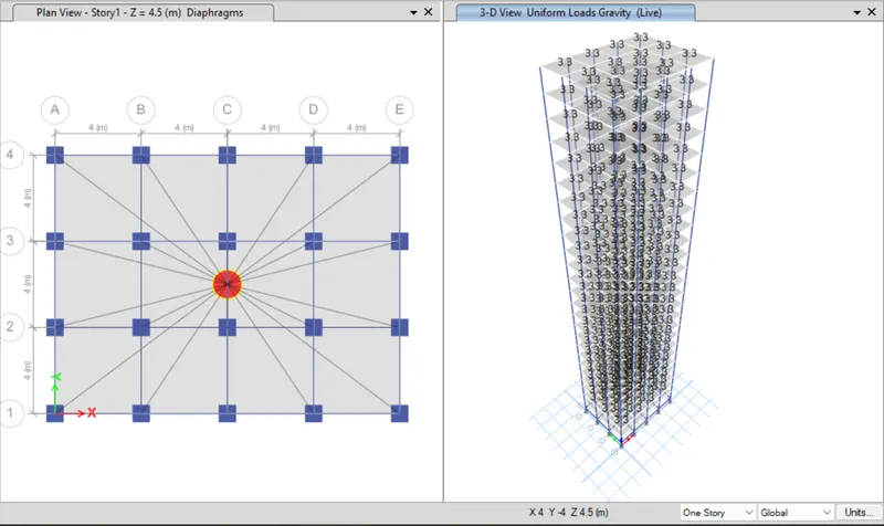
- Then go to assign-->shell loads-->uniform-->increase it by 10%
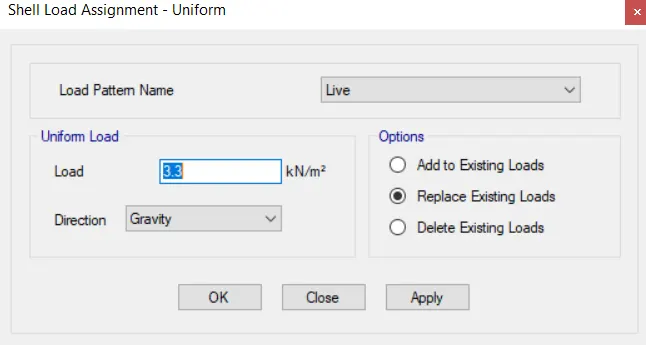
- We need to replace the exsisting imposed load with 3.3KN/m2
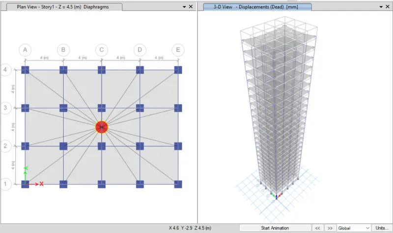
RUN THE ANALYSIS
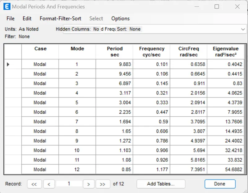
MODAL RESPONSE FOR BUILDING J
10. BUILDING K(G+25)
Same as BUILDING J instead 10% We need to increase 20% the imposed loads
- From BUILDING G go to the files and click on the save as option
- And name it as "BUILDING J"
- The model is set for changes as per the requirements of building J
- Select the slab 150 slab section
- Then go to assign-->shell loads-->uniform-->increase it by 20%
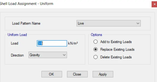
- We need to replace the exsisting imposed load with 3.6KN/m2
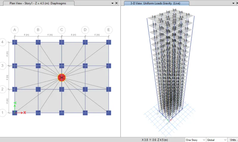
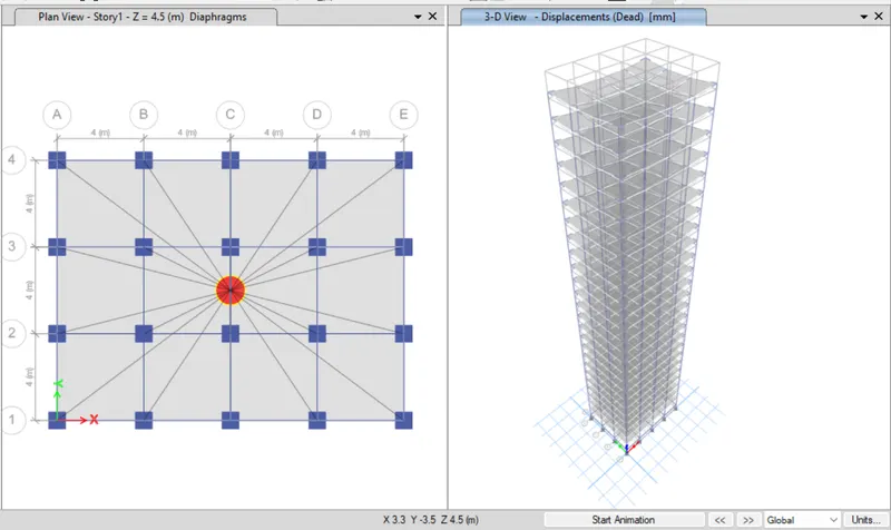
RUN THE ANALYSIS
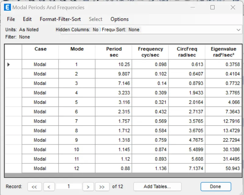
MODAL RESPONSE FOR BUILDING K
COMPAIRING RESULTS ON THE BASIS OF GIVEN TASK
1. Effect of stiffness on T: Compare fundamental natural periods of buildings E &F as well as G & H. Why is there a marginal or significant difference in the fundamental natural periods?
- The fundamental Natural period of building E is 1.323 sec
- The fundamental Natural period of building F is 1.256 sec
- The fundamental Natural period of building G is 3.192 sec
- The fundamental Natural period of building H is 3.372 sec
Reason:
- On comparing E and F, the significant changes in the time period is caused because we used Two different type of column sizes in Building E and only One type of column in F building.
- on comparing G and H. The significant changes in the time period are caused because we used three different type of column sizes In Building & and only one type of column in H building.
2. Effect of mass on T: Compare fundamental natural periods of buildings H, J and K. Have the buildings become more flexible or stiff due to change in mass?
- The fundamental Natural period of building H is 2.972 sec
- The fundamental Natural period of building J is 3.172 sec
- The fundamental Natural period of building K is 3.2372 sec
Reason:
- On comparing the fundamental natural periods of buildings H, J and K we can see a no change in time period of H comparing to J and K, as well as the time period is constant in J and K. these small changes happened because of bit increment in live load.
- From this we can say that, as the stiffness, mass, storeys of building increases natural period increases.
- Also the weight of building is directly proportional to the flexibility of the structure.
3. Effect of Building Height on T: How does the fundamental natural periods of Buildings A, B, F and H change with change in building height?
- The fundamental Natural period of building A is 0.518 sec
- The fundamental Natural period of building B is 1.073 sec
- The fundamental Natural period of building F is 1.256 sec
- The fundamental Natural period of building H is 3.372 sec
Reason:
- On comparing A, B, F. & H: we can say that as the height of the building gets increased, the time period of the building also increases.
- so, time period is directly proportional to Height of building
4. Effect of Column Orientation on T: How does the fundamental natural periods of Buildings B, C and D change with change in column orientation?
- The fundamental Natural period of building B is 0.518 sec
- The fundamental Natural period of building C is 1.173 sec
- The fundamental Natural period of building D is 1.173 sec
Reason:
- On comparing B, C, & D: we can see that the time period of C is equal to D which Intern is more than B
- So, the stiffness of building is more if the columns are oriented in longer length direction.
5. Effect of Flexural Stiffness of Structural Elements on mode shapes: Compare fundamental mode shape of Building B in two situations when flexural stiffness of beams relative to that of adjoining columns is very small versus when it is large.
- On Comparing fundamental mode shape of Building B in two situations when flexural stiffness of beams relative to that of adjoining columns is very small versus when it is large.
- For situation when flexural stiffness of beams is smaller than adjoining column:
6. Effect of Axial Stiffness of Vertical Members on mode shapes: Compare fundamental mode shape of Building H in two situations when axial cross-sectional area of columns is very small versus when it is large.
- On Comparing fundamental mode shape of Building H in two situations when axial cross-sectional area of columns is very small versus when it is large.
- For situation when axial cross-sectional area of columns is very small