Project 1_Comparative study of different storey buildings for Seismic forces
AIM:
We have multiple building with different parameter so, that we need to compare their result and overall seismic behaviour by using ETABS software like factor influencing the dynamic characteristics of building, time period of building and mode shape of building.
INTRODUCTION:
In the various modal is different structural and geometrical configuration so, we extract different seismic responses and comparison of analysis result for each of the criteria then identifying the reason for influences and reporting them. We analyse certain properties in etabs modal
Procedure for Building A
Building A is a 2 Storey building with the similar base, 4m in X direction and 3m in Y direction. We have given the size of elements, material properties, loading details and elevation
STEP 1) Create New Model
- Click on New Modal from ETABS home interface
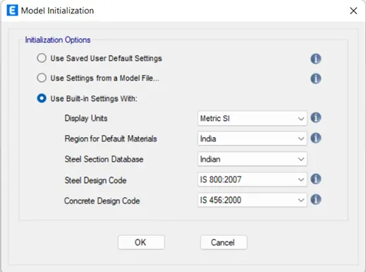
- Select Unit Built in Setting from Modal Initialization dialog box
- Change display unit as METRIC SI
- Region for default material as INDIA
- Steel selection database INDIAN
- Steel design code IS-800:2007
- Concrete design code IS-456:2000 enter OK
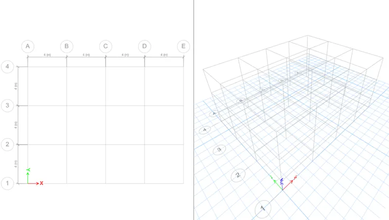
STEP 2) Create Grids
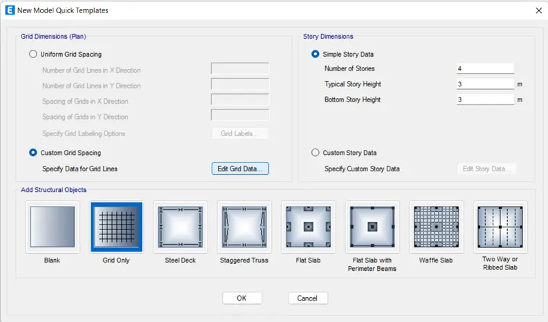
- A new dialog box opened as New Modal Quick Templates
- Select Custom Grid Spacing and click on the Edit Grid Data
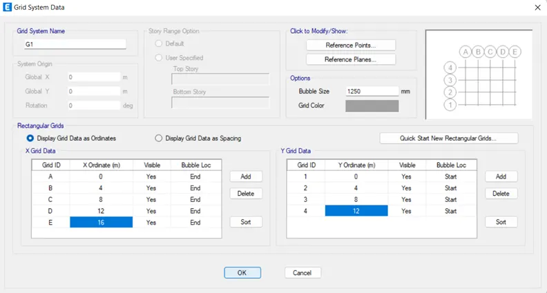
- Modify the X & Y Grid Data from the Grid System Data dialog box and click OK
STEP 3) Add Building Storey
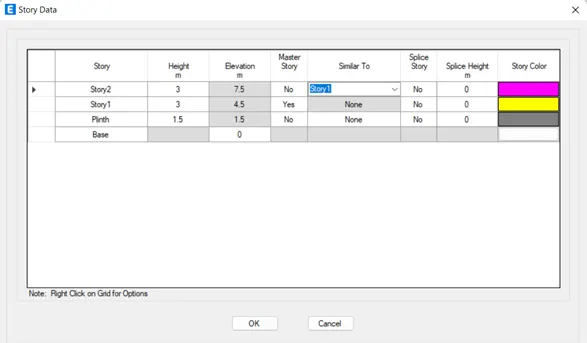
- Select Custom Story Data and click on Edit Story Data
- A new dialog box open as Story Data
- Rename the levels of the story 1,2 & 3 as plinth and story 1 &2 respectively
- Only plinth level height is 5 and story 1 & 2 height is 3
- Story 1 as master story so, select yes, towards the story 1
- Change story 2 similar to story 1
STEP 4) Define Material
- The grid arrangement of the new modal will open
- Go to Define and click Material Property
- Define Material dialog box will open, click on Add New Material
- Add New Material dialog box will open, select Material Type Concrete and ensure Grade M30 click OK
- Material Properly Data dialog box will open, click OK
- Again, click on Add New Material
- Add New Material dialog box will open, select Material Type Rebar and select Grade HYSD 415 click OK
- Material Properly Data dialog box will open, click OK

STEP 5) Add Column, Beam
- Go to Define tab, and select Frame Section from Section Property
- Click on Add New Property from Frame Properties dialog box
- Click on Rectangular Section for Beam from Frame Property Shape Type
- Change the Property Name as B300X400 and Material M30 and section dimension Depth as 400 & width as 300 from Frame Section Property Data, click on Modify/Show Rebar under Reinforcement
- Change Design Type and Rebar Material, click OK
- Again, Add New Property for Column and select Rectangular Section
- Change the Property Name, Material and Dimension and Modify/Show Rebar similarly

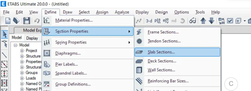
STEP 6) Add Slab
- Go to Define, Select Slab Section from Section Property
- Click on Add New Property for Slab
- Change the Property Name, Slab Material, Modeling Type and Thikness of Slab
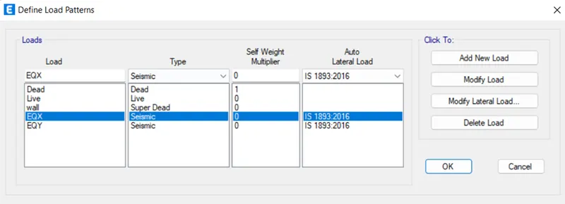
STEP 7) Load Pattern
- Go to Define and select Load Patterns
- Add Wall Load as Super Dead type
- Simalry add EQX & EQY Load as Seismic type and select IS-1893:2016
- Modify the lateral load and uncheck the other direction except X for EQX and Y for EQY
- Change the zone as per code 16
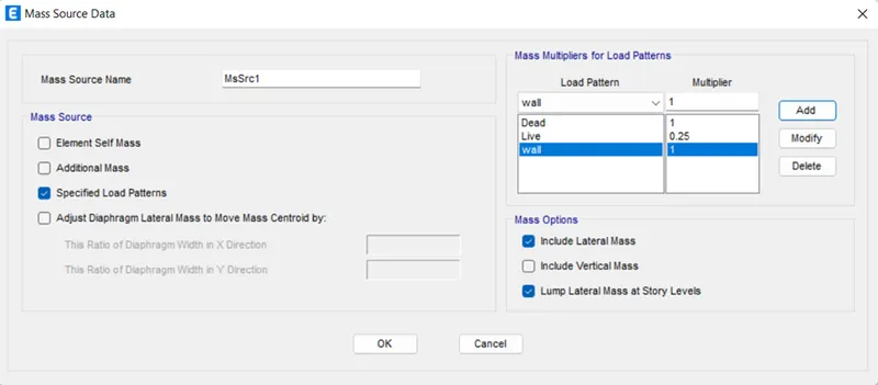
STEP 8) Define Mass Source
- In Define tab Select Mass Source
- Click on Modify/Show Mass Source
- Check mark only Specified Load Pattern
- Add wall, live and dead load
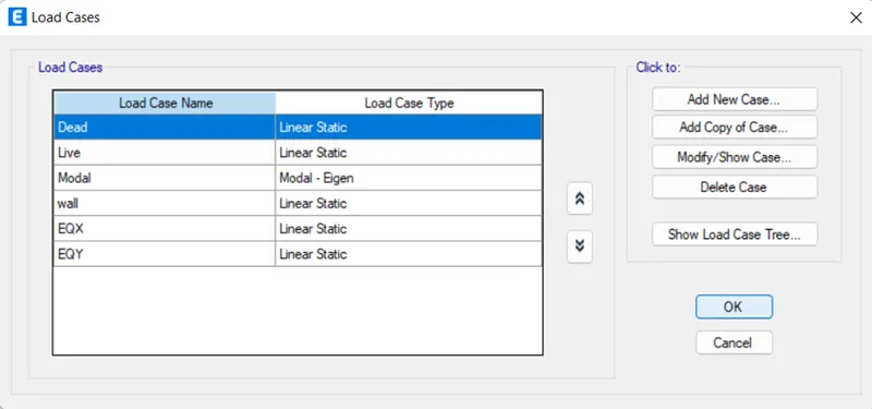
STEP 9) Check Load Case
- Go to Define and select Load Cases
- Check load cases and click OK
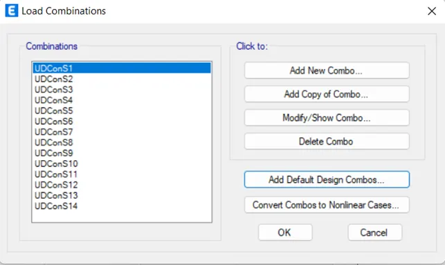
STEP 10) Load Combinations
- Go to Define select Load Combinations
- Add Default Design Combination
- Check on Concrete Frame Design and Convert To User Combination
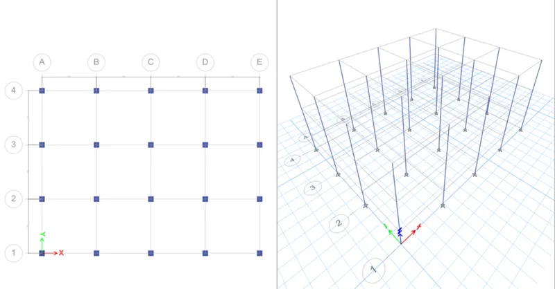
STEP 11) Draw Column
- Select Quick Draw Column
- And change the
- Select All Stories
STEP 12) Draw Beam
- Select Quick Draw Beam and change the Property
- Click Between Two Columns and place the beam X & Y Direction

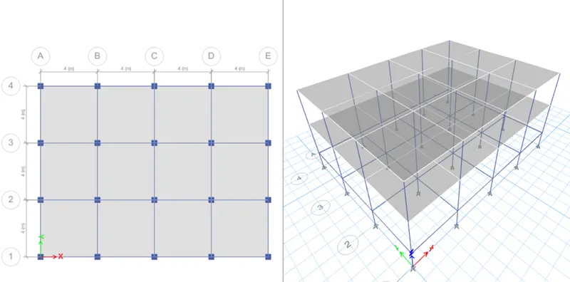
STEP 13) Draw Slab
- Change set plan as Stroy 1 and Similar Stories
- Select Quick Draw Floor icon and change the Property
- Click on the Boundries Of The Grid
- Slab will be created for all floor
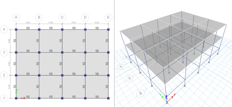
STEP 14) Assign Load & Diaphragms
- Select all Beam
- Assign Frame Load as a Distributed
- Load Pattern Name Wall and Uniform Load 10kn/m
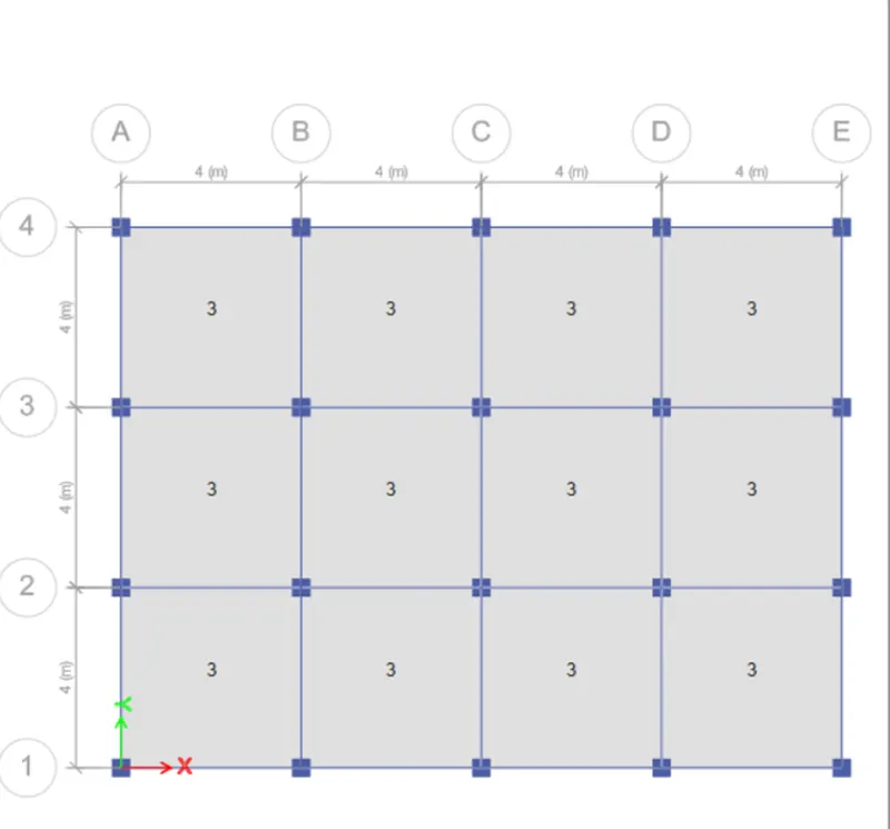
- Similarly select slab
- Assign shell load as uniform
- Load Pattern Name live and Uniform Load 3 kn/m
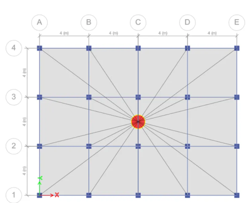
- Select Slab
- Assign Shell as Diaphragms
STEP 15) Run Analyse the Model
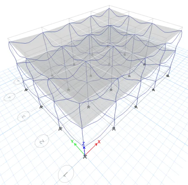
- Click on Run Analysis Button to get analyse result
Procedure for Building B
- Building B is a 5 Storey building similar to building A with the same base, 4m in X direction and 3m in Y direction.
- Material and size of column are similar to building A
- Saved a copy of building A for building B
- Add 3 more story above the existing storey
- Check the floor & frame load to be visible
- Ensuring the slab to be assigned as a diaphragm
- Run and analyse the result
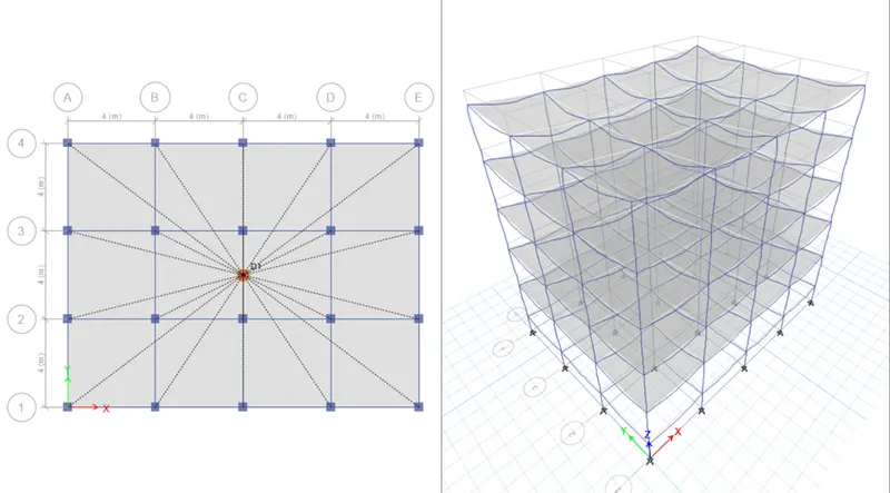
Procedure for Building C
- Building C is a 5 Storey building but column sizes are different with the same base, 4m in X direction and 3m in Y direction.
- Saved a copy of building B for building C
- Modify the existing column size as 550X300
- Rotate the column by 90-degree angle in X direction
- Check the load and diaphragm as building B
- Run and analyse the result
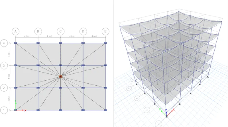
Procedure for Building D
- Building D is similar to building C
- Saved a copy of building C for building D
- Only we have to change the orientation of the column in Y direction
- Check the load and diaphragm as building C
- Run and analyse the result
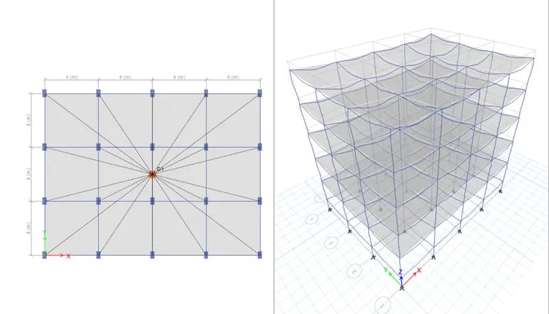
Procedure for Building E
- Building E is 10 story with different column size but same base
- Saved a copy of building D for building E
- Add 5 more story above the existing storey
- Modify the existing column size as 600X600 and add new column 400X400
- For story 6 to story 10 change the column size as 400X400
- Check the load and diaphragm as building E
- Run and analyse the result
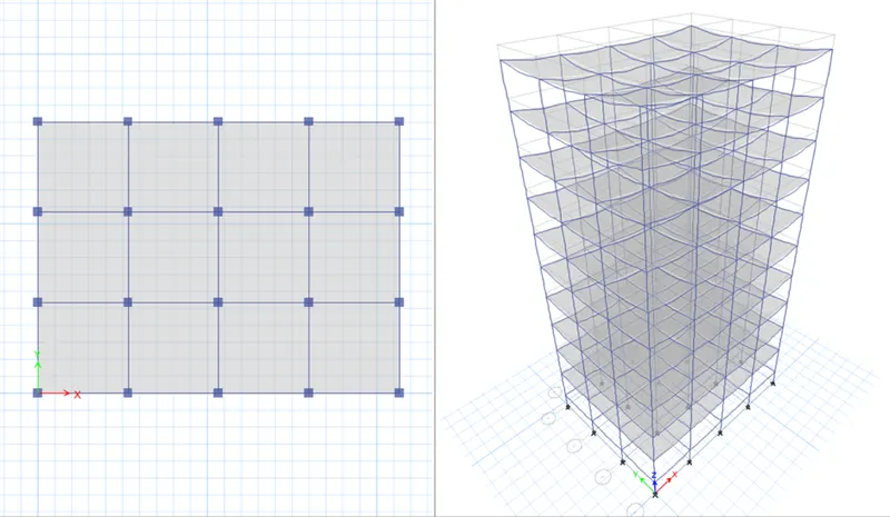
Procedure for Building F
- Building F is 10 story with same column sizes and same base
- Saved a copy of building E for building F
- For story 6 to story 10 change the column size as 600X600
- Check the load and diaphragm as building E
- Run and analyse the result
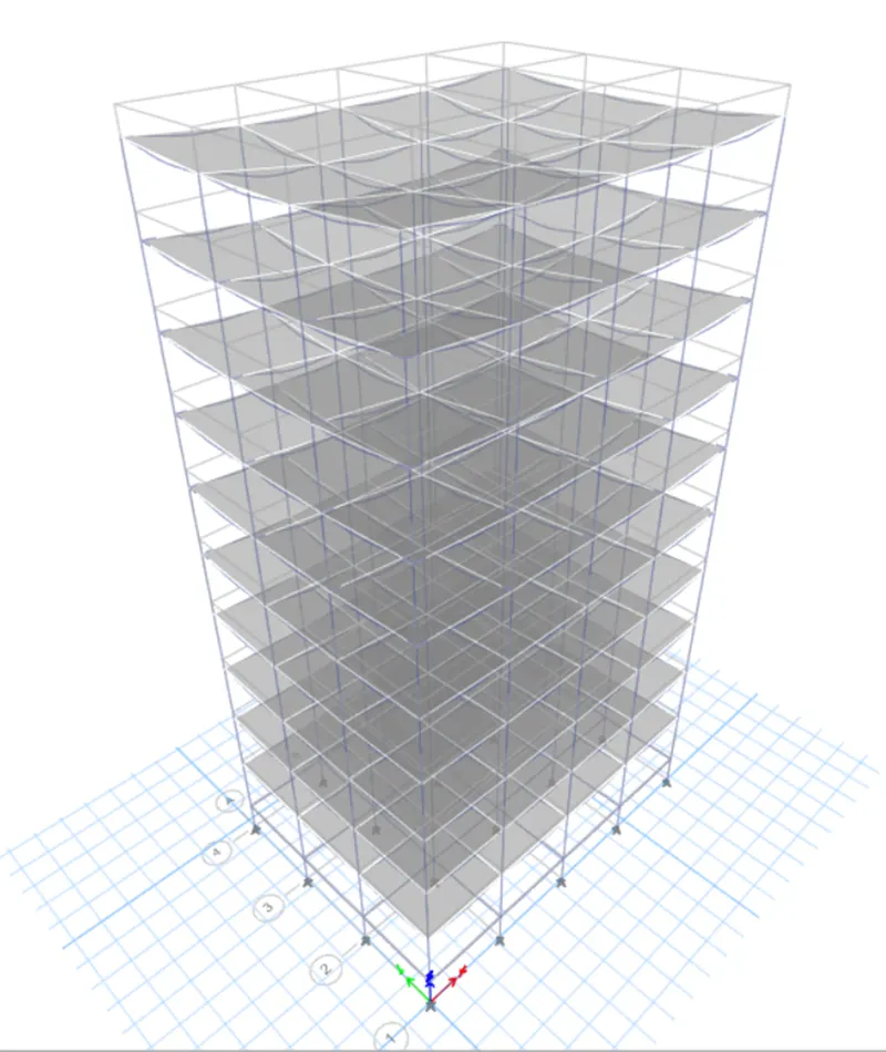
Procedure for Building G
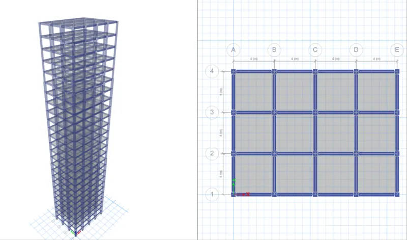
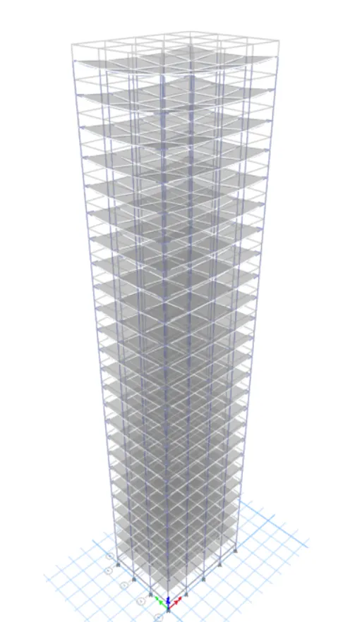
- Building G is 25 story with 3 different column size but same base
- Saved a copy of building F for building G
- Add 15 more story above the existing storey
- Modify the existing column size 600X600 to 800X800 and add new column 600X600
- For story 21 to story 25 change the column size as 400X400
- For story 11 to story 20 change the column size as 600X600
- Check the load and diaphragm as building F
- Run and analyse the result
Procedure for Building H
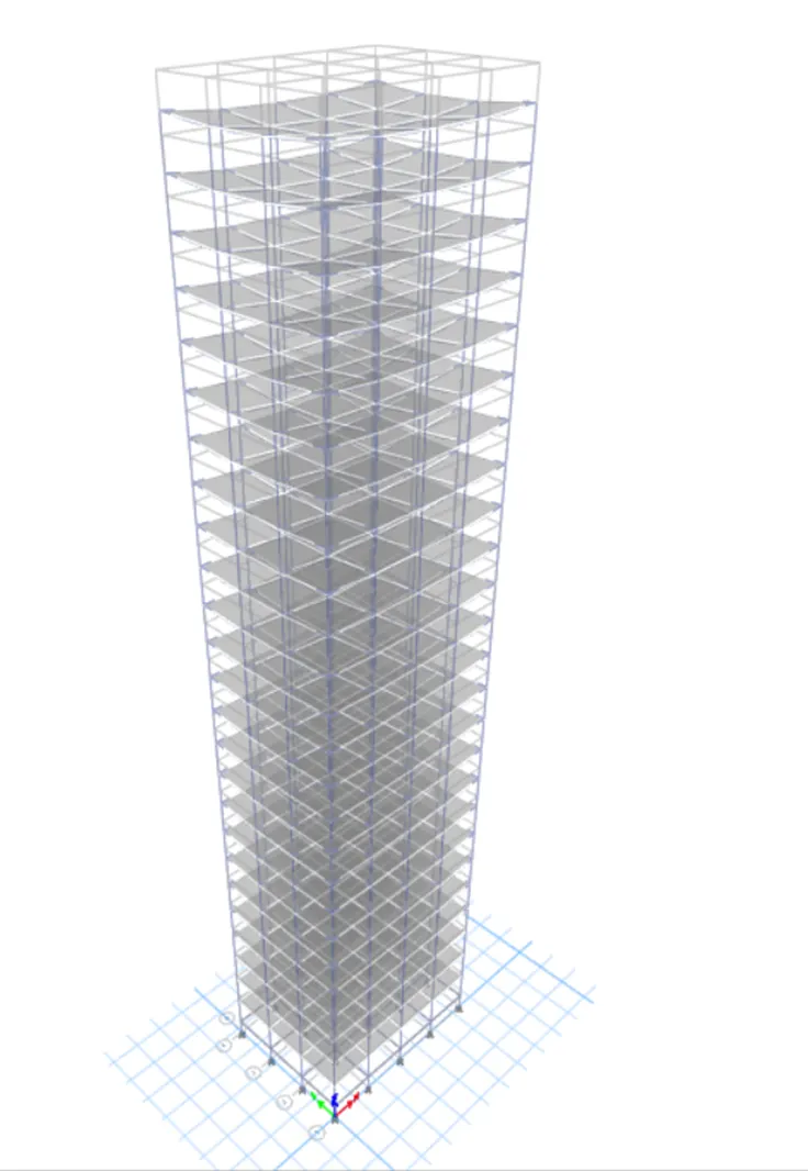
- Building H is 25 story with similar column size and same base
- Saved a copy of building G for building H
- Change the existing column size as 800X800
- Check the load and diaphragm as building G
- Run and analyse the result
Procedure for Building J
- Building J is 25 story with similar column and base only we need to increase imposed mass by 10% higher
- Saved a copy of building H for building J
- Select all the slab assign shell load> uniform 3.3kN/m2
- Run and analyse the result
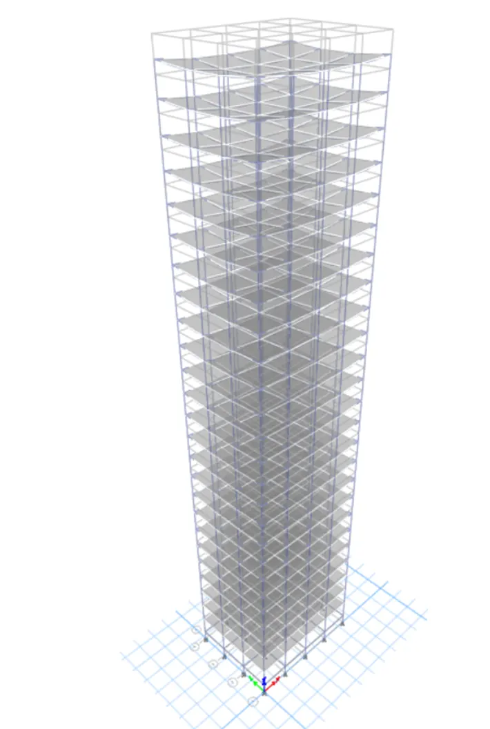
Procedure for Building K
- Building K is 25 story with similar to building J only we need to increase imposed mass by 20% higher
- Saved a copy of building J for building K
- Select all the slab assign shell load> uniform 3.6kN/m2
- Run and analyse the result
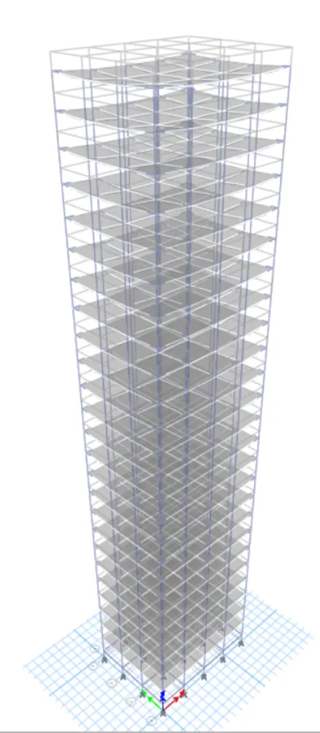
Comparison the analysis result between the time period in various condition
|
Criteria |
Modal |
Analysis Result |
conclusion |
|
Effect of stiffness on time period |
Building-E (10 storey with varying column size) |
1.73 second |
|
|
Building-F (10 storey with uniform column size) |
1.73 second |
||
|
Effect of stiffness on time period |
Building-G (25 storey with varying column size) |
4.17 second |
|
|
Building-H (25 storey with uniform column size) |
4.41 second |
|
Criteria |
Modal |
Analysis Result |
conclusion |
|
Effect of mass on time period |
Building-H (25 storey with 3 kN/m2 imposed load) |
4.41 second |
|
|
Building-J (25 storey with 3.3 kN/m2 imposed load) |
4.42 second |
||
|
Building-K (25 storey with 3.6 kN/m2 imposed load) |
4.43 second |
|
Criteria |
Modal |
Analysis Result |
conclusion |
|
Effect of building height on time period |
Building-A (2 storey) |
0.5 second |
|
|
Building-B (5 storey) |
1.03 second |
||
|
Building-F (10 storey) |
1.73 second |
||
|
Building-H (25 storey) |
4.41 second |
|
Criteria |
Modal |
Analysis Result |
conclusion |
|
Effect of column orientation on time period |
Building-B (all floors column size 400X400) |
1.03 second |
|
|
Building-C (all floors column size 550X300) X-direction |
1.145 second |
||
|
Building-D (all floors column size 300X550) Y-direction |
1.12 second |
|
Criteria |
Modal |
case |
Analysis Result |
conclusion |
|
Effect of flexural stiffness of structural elements on mode of shapes |
Building-B |
Flexural stiffness of beams close to nil (zero inertia) |
2.62 second |
|
|
Full flexural stiffness of beams (regular) |
1.03 second |
|
Criteria |
Modal |
case |
Analysis Result |
conclusion |
|
Effect of axial stiffness of vertical members on mode shapes |
Building-H |
Axial cross section for columns is closed nil (Zero axial area) |
5.99 second |
|
|
Full axial cross section for columns (regular) |
4.41 second |
|
Criteria |
Modal |
case |
Analysis Result |
conclusion |
|
Effect of degree of fixity at column base on mode shapes |
Building-B |
Column support pinned (regular) |
1.03 second |
|
|
Column support fixed |
0.941 second |