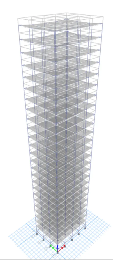
Project 1_Comparative study of different storey buildings for Seismic forces
Your Answers
1. Builduing A
As given the Building A is a 2 Storey building with the similar base, 4m in X direction and 3m in Y direction. and we have to define materials etc.
Step 1: Open the ETABS Software
- Install the ETAB software from CSI Website
- After complete the installation, Launch ETABS 2022 software from windows
- ETABS home interface will be open as shown below.
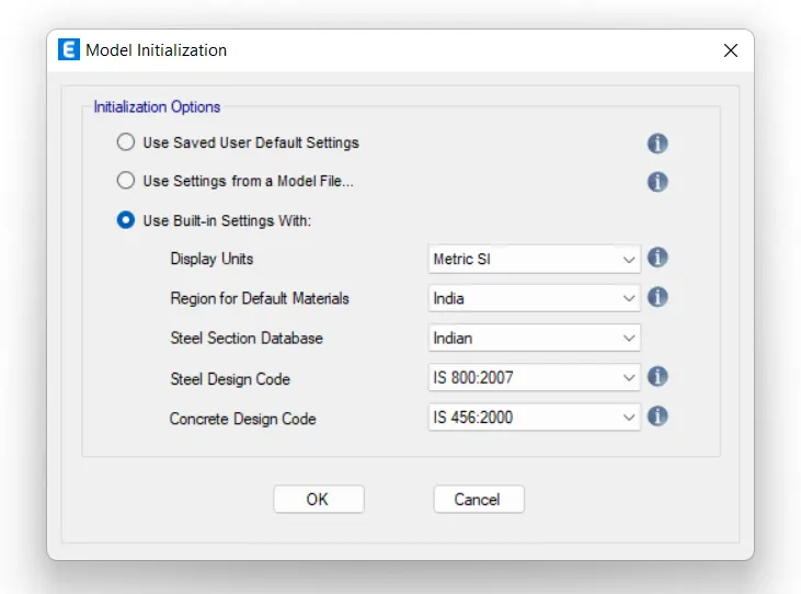
Step 2: Make a New Model.
- Click on New Model from ETABS home interface
- Change the readings as shown in the image.
Step 3: Making reference grids lines for the model.
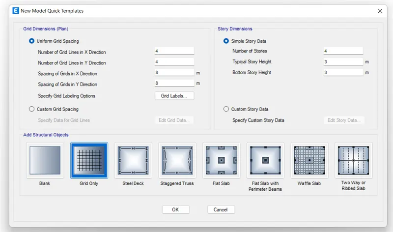
- A dialogue box will open as New Model Quick Templates
- Select Custom Grid Spacing.
- Click on the Edit Grid Data
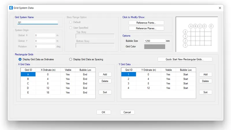
- Modify the X & Y Grid Data from the Grid System Data dialog box
- Click OK
Step 4: Add building storey
- Select Custom Story Data and click on Edit Story Data
- A new dialog box open as Story Data
- First of all delete the one story
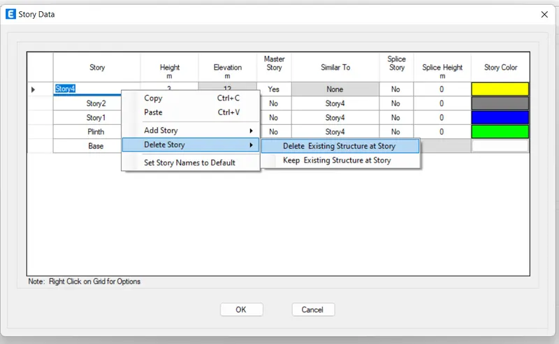
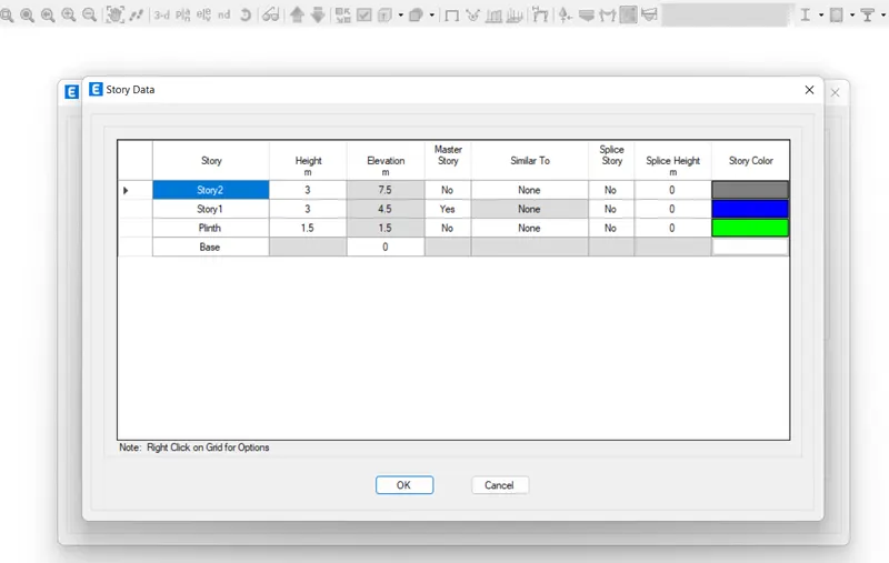
- Rename the levels of the story 1,2 & as plinth and story 1 &2 respectively
- Only plinth level height is 1.5 and story 1 & 2 height is 4.5 & 7.5
- Story 1 as master story so, select yes, towards the story 1
- We need only 2 story and One is plinth level.
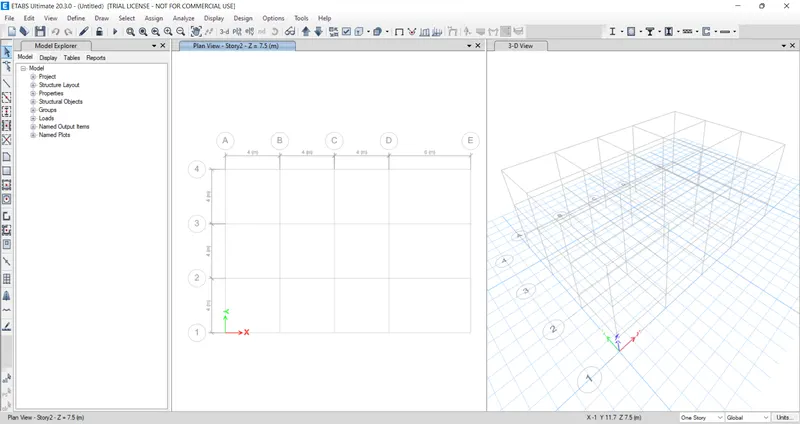
Step 5: To Define materials i.e. (Concrete and Rebars)
- Click on Define
- Then click on Material Property
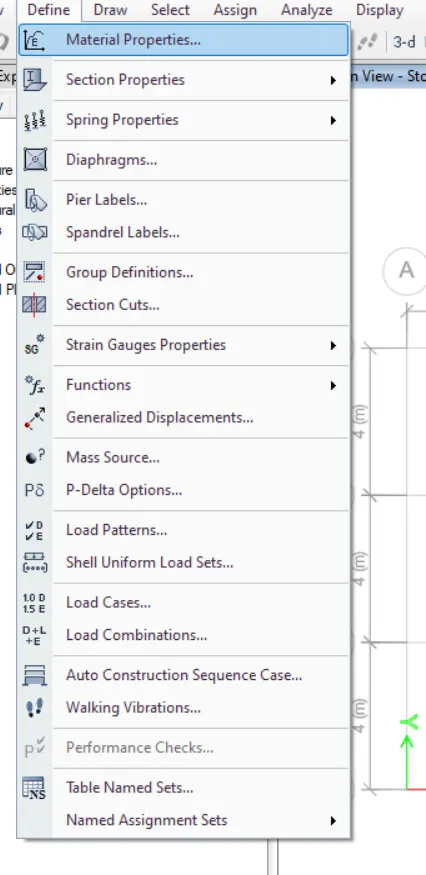
- Then click on Add New Material
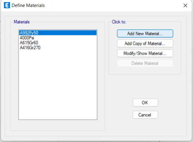
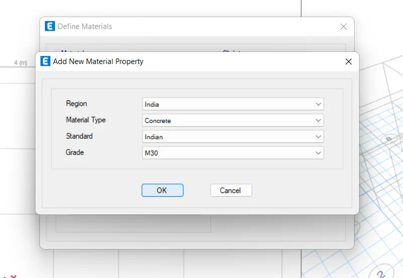
- Select Material Type Concrete and ensure Grade M30
- Click OK.
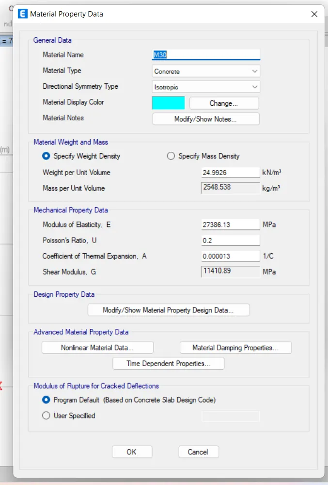
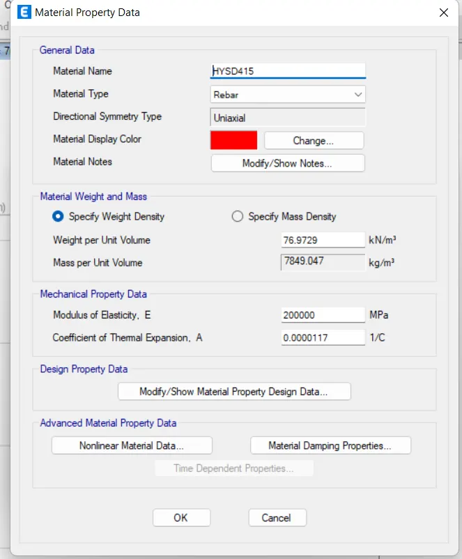
- Now again click on Add New Material
- Select Material Type Rebars and ensure Grade HYSD 415
Step 6: To define Section properties and adding column and beam.
Adding Beams
- Click on Define tab from the Title box
- Select Frame Section from Section Property
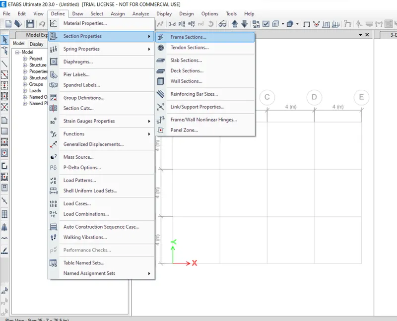
- Click on Add New Property from Frame Properties dialog box
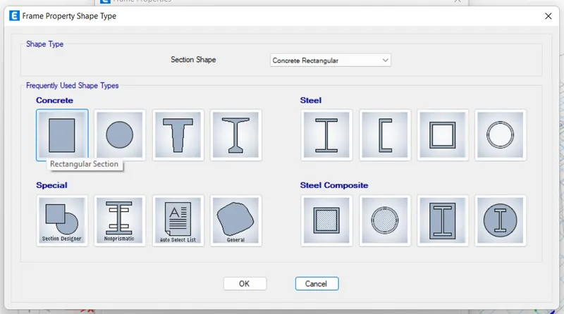
- Click on Rectangular Section for Beam from Frame Property Shape Type
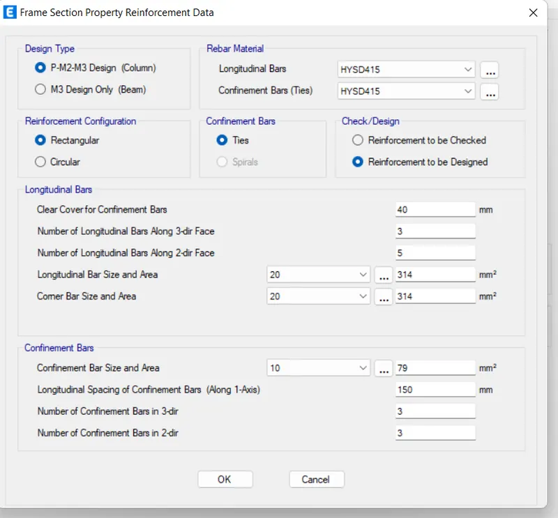
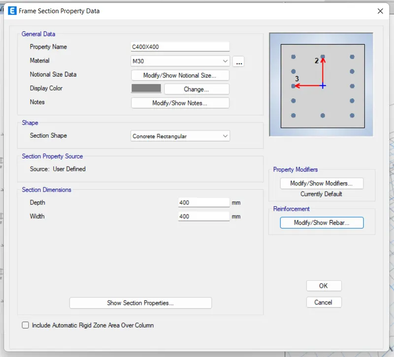
- Change the readings as per given in the image below.
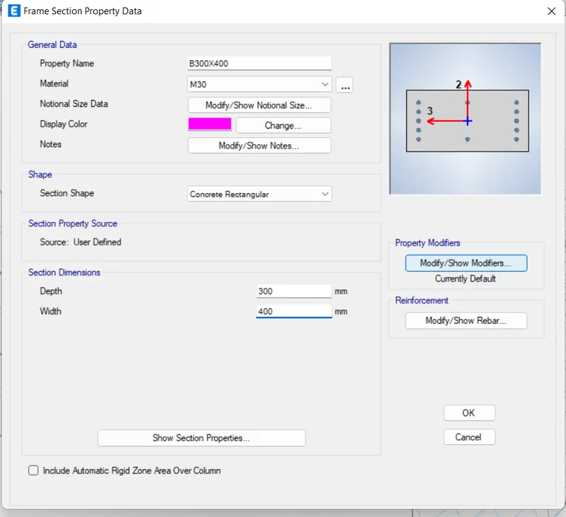
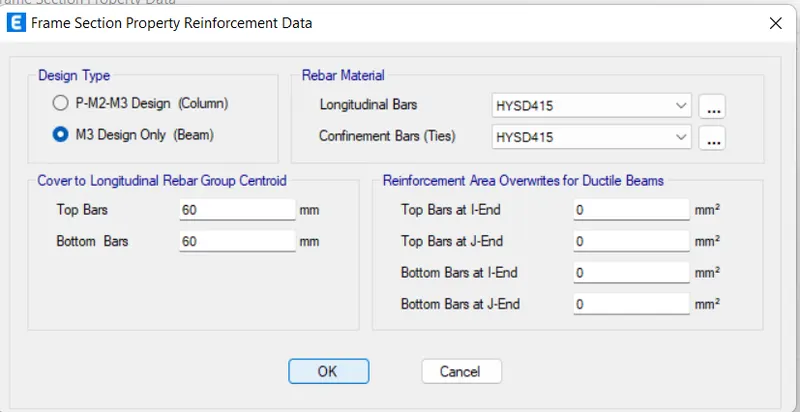
- Now click on Modify/show/rebars
- thenselect M3 Design Beam only
Adding Columns
- Repeat above steps but change the Readings.
Step 7: Adding Slab.
- Click Define, Select Slab Section from Section Property
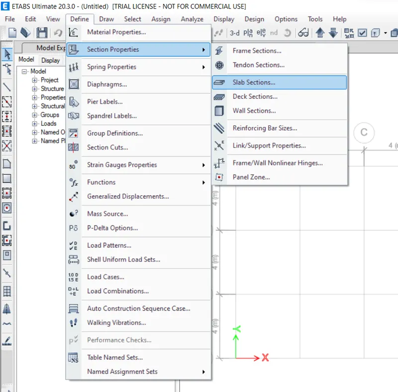
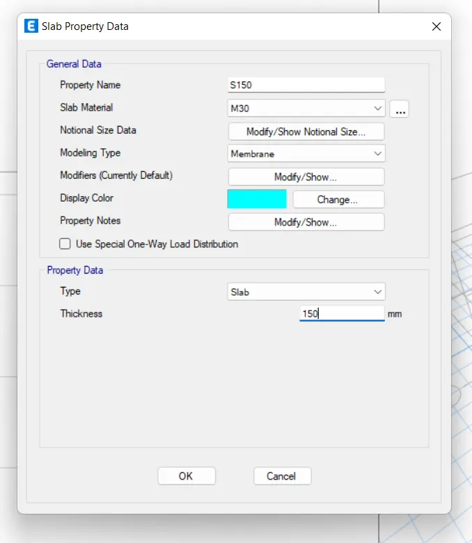
- Click on Add New Property for Slab
- Change the Property Name, Slab Material, Modelling Type and Thickness of Slab
Step 8: Load Pattern
- Click on Define and select Load Patterns.
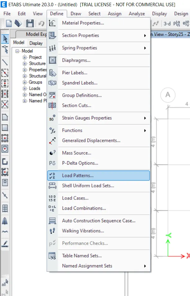
- Add the Live, Dead and Wall load.
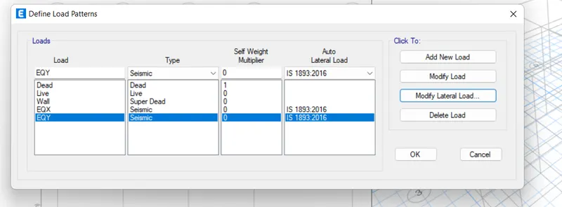
For eatrhquae X
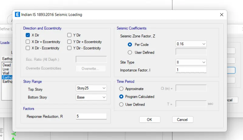
For EQY
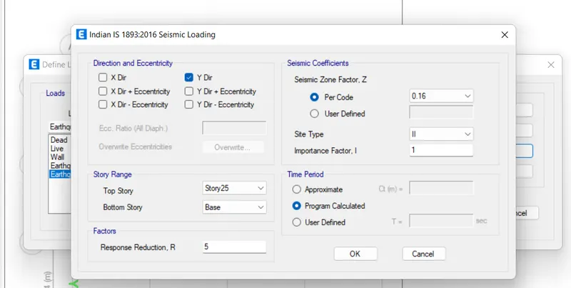
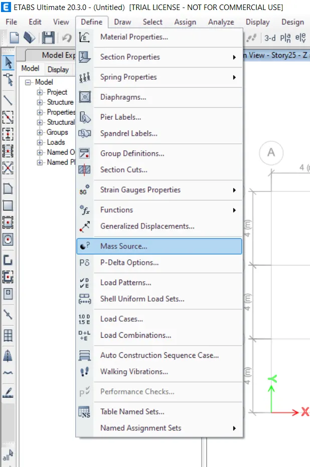
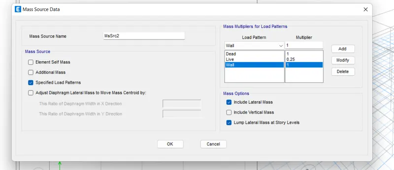
Step 9: Define Mass Source
- In Define tab Select Mass Source
- Click on Modify/Show Mass Source
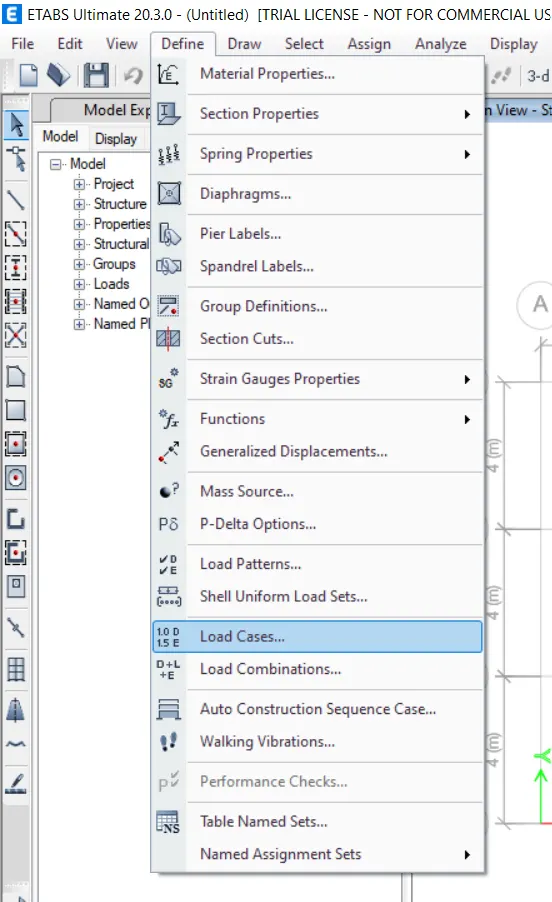
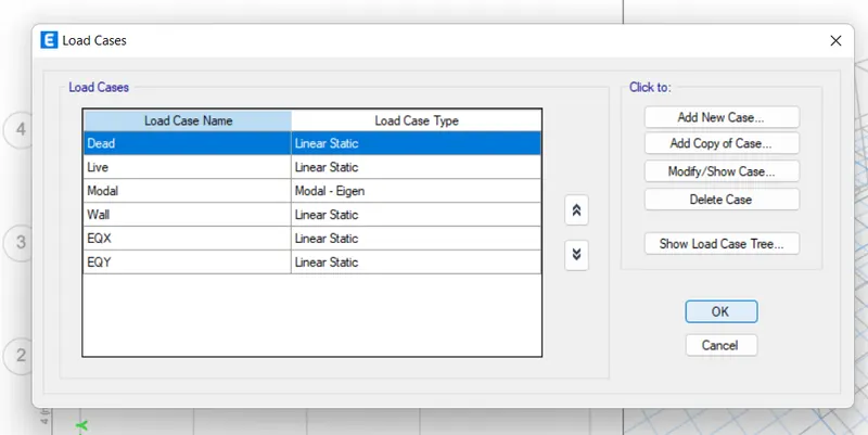
Step 10: Check the load cases we have made.
- Click on Define
- Then click on Load cases
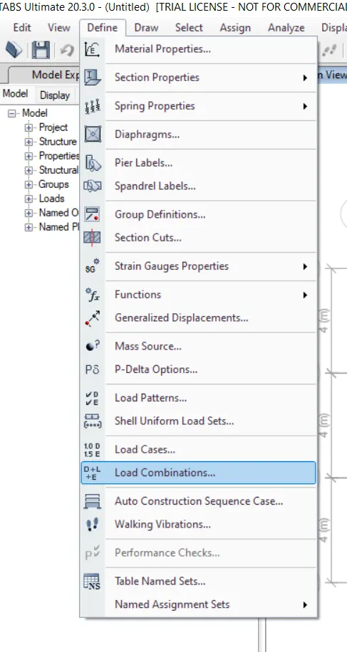
Step 11: Adding Load combinations.
- Click on Define
- Then click on Load combination
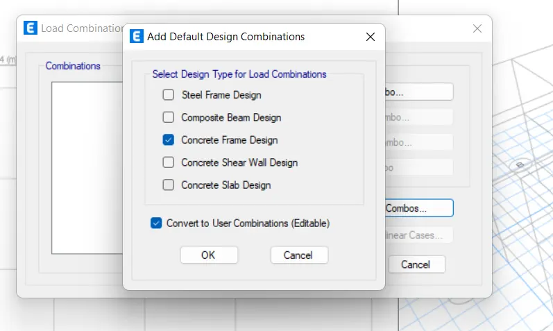
- Click on concrete frame design.
Now we have to Draw the Columns, Beams and the Slabs to the structure we have provided for this follow the given steps below:
Step 1: First we have to draw the Columns
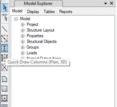
- Select Quick Draw Column
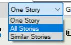
- Select All Stories
- Select the specified column from property browser in left bottom side.
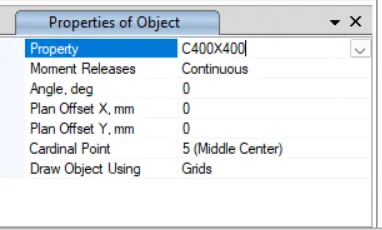
- Click on Left Most Y Direction Grid to place the column
- The columns are drawn.
Step 2: To draw the Beams:
- Select Quick Draw Beam and change the Property
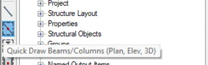
- Click Between Two Columns and place the beam X & Y Direction
Step 3: To create the Slabs:
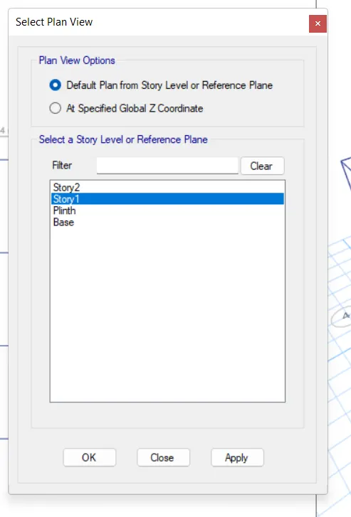
- Select the plan from the Title Box

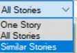
- Then change the. Set plan as a story one and similar stories.
- Now select the S150 from the property
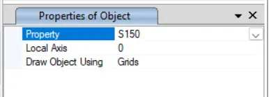
- Then click on the boundaries of the grid to create the slab.
Result:
The columns and beams and slab are created.
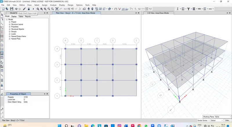
Now we have to assign the loads and Add Diaphgrams to the given structure we have created. For this follow these steps given below.
Step 1: To Assign the loads
- Select all Beam
- Assign Frame Load as a Distributed
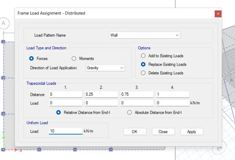
- Give the loads as 10 kn
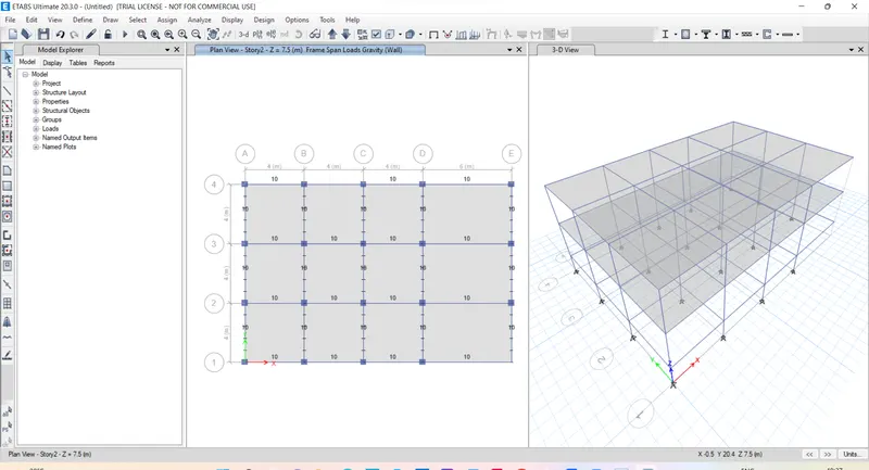
- Now select all the slabs
- Assign shell load as uniform
- And apply load as 3 kn
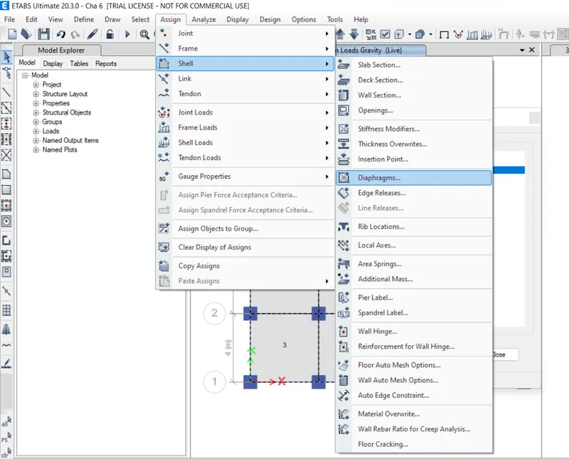
Step 2: To Add Diaphragms
- Select Slab
- Assign Shell as Diaphragms
- You see the centre load is drawn at your ETABS screen.
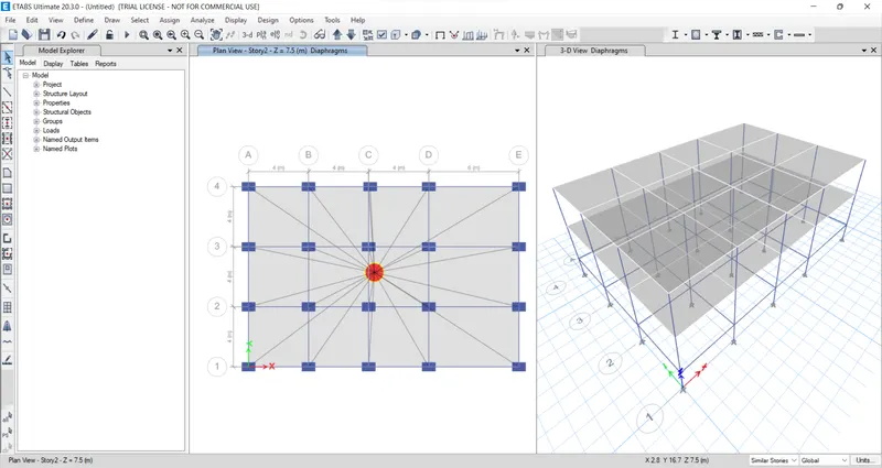
Result Analysis.
Now we have to Run and Analyse the model So,
Step 1: Run Analyse the Model
- Click on Run Analysis Button
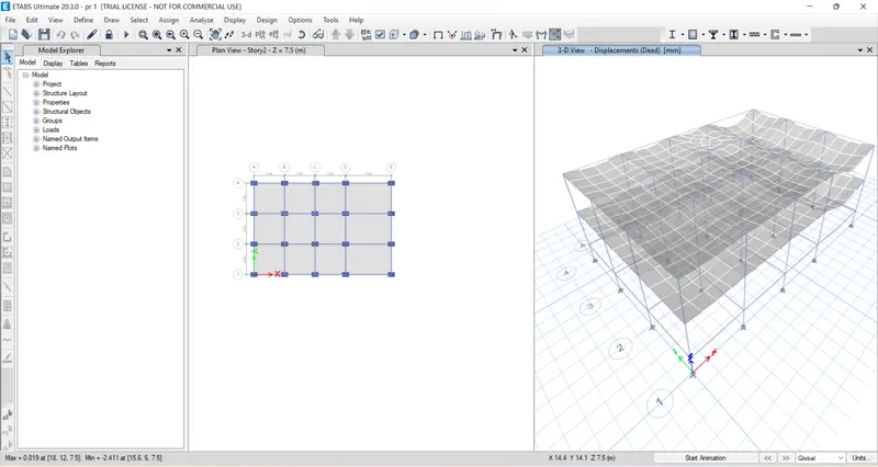
2. Building B
In the table it is given that the builduing B is a 5 storey so we have to change the storey settings and size the same base, 4m in X direction and 3m in Y direction but Similarly we have to define materials and loads and draw the beams and columns for builduing B.
For this.
Steps for Building B
- The Material and size of column are similar to building A.
- Now Save a copy of building A for building B
- Add 3 more story above the existing storey
- Check the floor & frame load to be visible
- Now Ensuring diaphragm
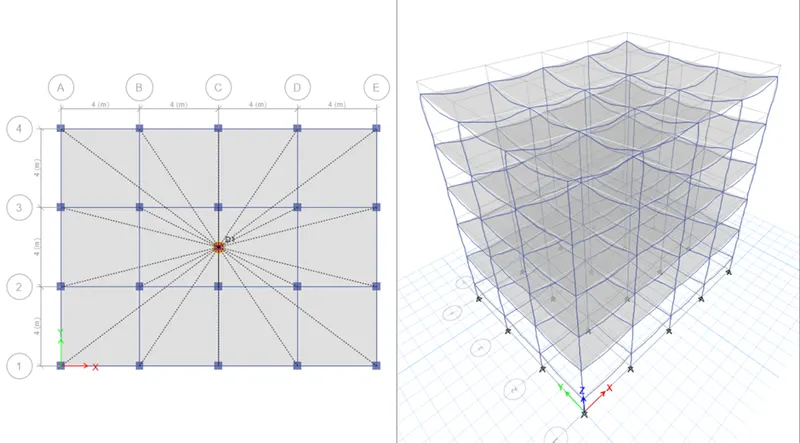
Result Analysis:
3. Building C
In the table it is given that the builduing B is a 5 storey, but column sizes are different with the same base, 4m in X direction and 3m in Y direction so we have to Modify the existing column size as 550X300
Steps for Building C
- Saved a copy of building B for building C
- Rotate the column by 90-degree angle in X direction
- Check the load and diaphragm as building B
Result Analysis:
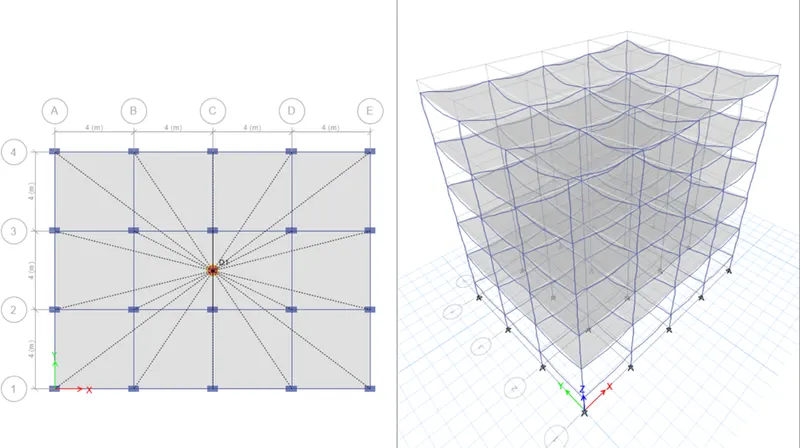
4. Builduing D
In the given table we see that Builduing D is Same as Builduing C. In this we have only change the orientaion of the column in Y direction.
Steps for Building D
- Saved a copy of building C for building D
- Check the load and diaphragm as building C
Result Analysis:
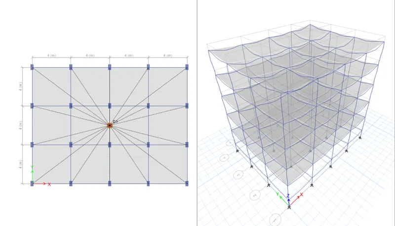
4. Builduing E
in the given table. I see that. Building is 10 Storey building with different column size but the same base. In this we have to modify the existing column size 600X600 but For Story 6 to 10 we have to change the column sizes 400X400.
Steps for Building E
- Saved a copy of building D for building E
- Add 5 more story above the existing storey
- Check the load and diaphragm as building E
Result Analysis:
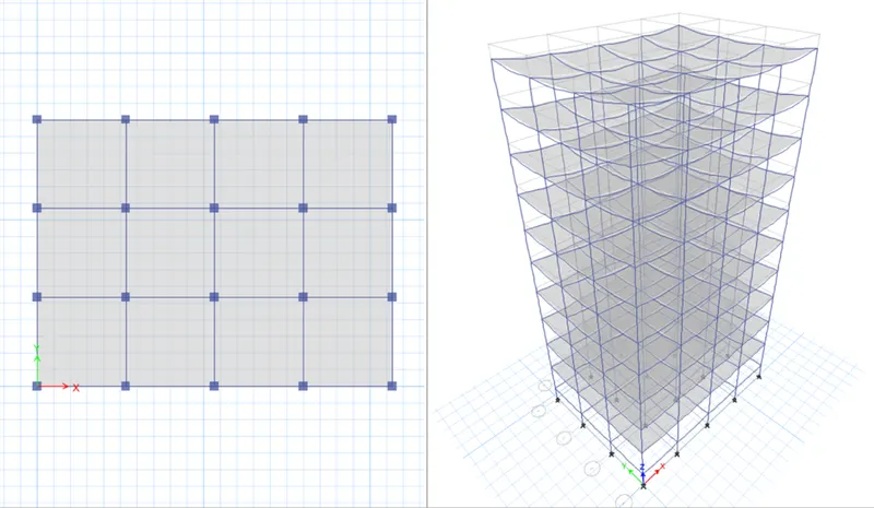
5. Builduing F
In the given table we observe the building given as a 10 story building with same column sizes and same base but we have to change the. 6 to 10 Storey buildings column size as 600 * 600.
Steps for Building F
- Saved a copy of building E for building F
- Check the load and diaphragm as building E
- Run and analyse the result
Result Analysis:
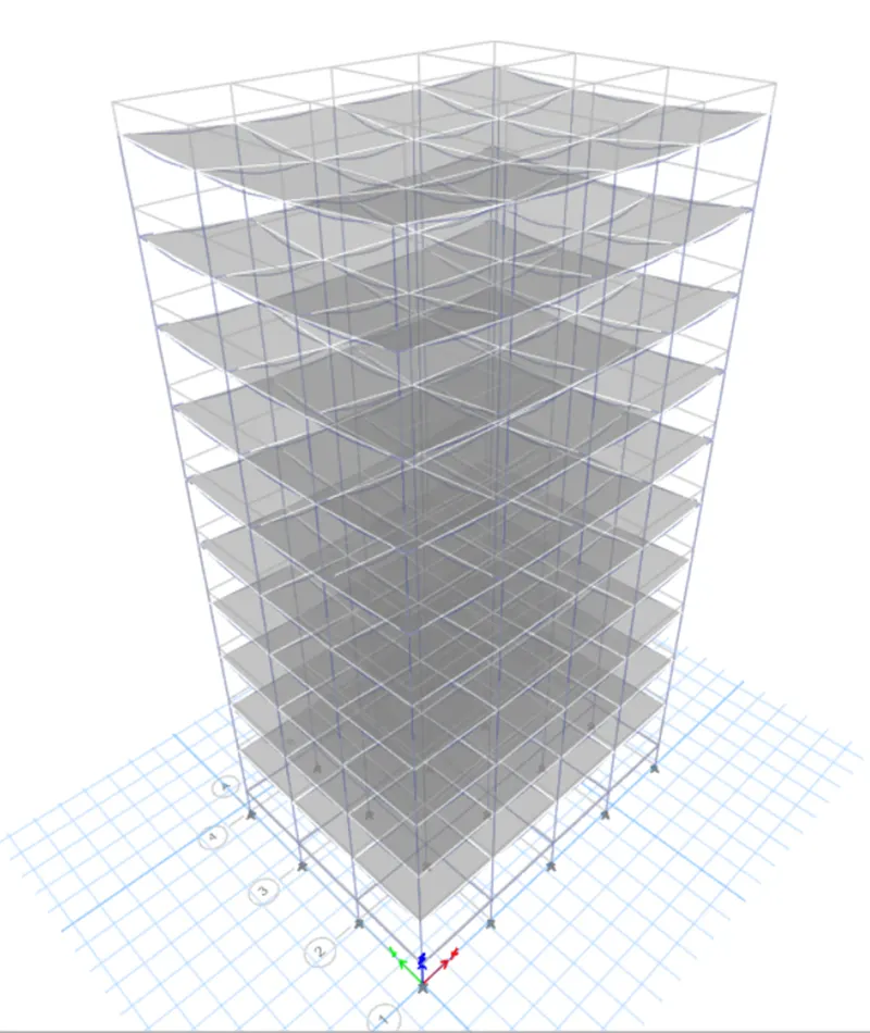
6. Builduing G
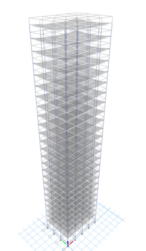
In the given table we see that Building G is a 25 story building with 3 different column size but they having same base.
Steps for Building G
- First of all Save a copy of building F and rename it as building G
Changes we have to do in building G.
- Add 15 more story above the existing storey
- Modify the existing column size 600X600 to 800X800 and add new column 600X600
- For story 21 to story 25 change the column size as 400X400
- For story 11 to story 20 change the column size as 600X600
- Check the load and diaphragm as building F
Result Analysis:
7. Builduing H.
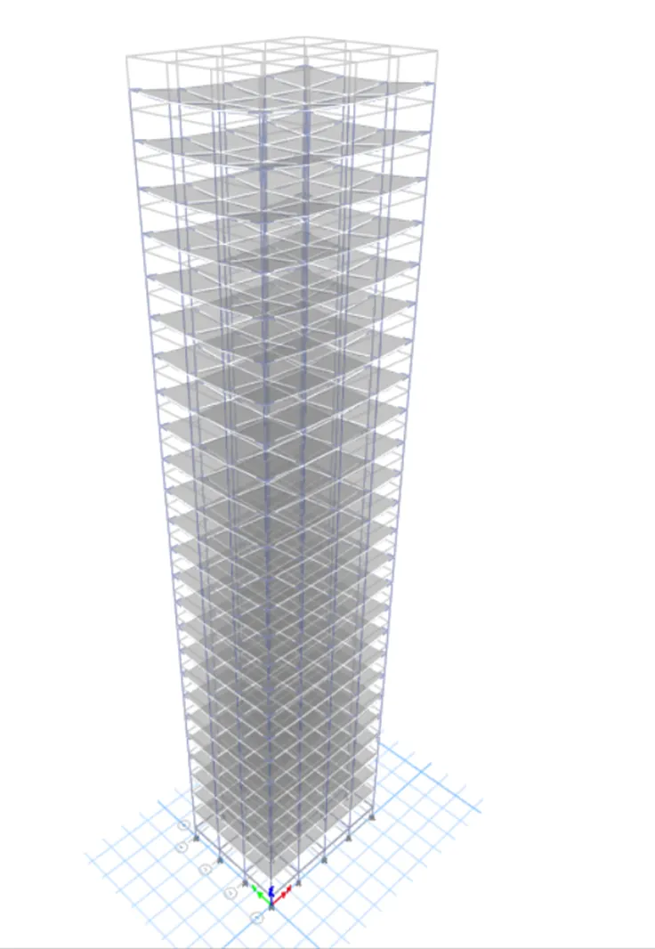
SVC in the table building is a. 25 story building with similar column size and same base.
Steps for Building H
- Saved a copy of building G for building H
Changes we have to do.
- Change the existing column size as 800X800
- Check the load and diaphragm as building G
Result Analysis:
8. Building J
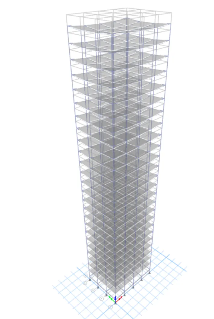
We see that building JE 25 story building with similar column and base.
Steps for Building J
- Saved a copy of building H and rename it as building J
Changes we have to do.
- we only have to need to increase imposed mass by 10% higher
- Now select all the slab assign shell load
- Assign shell load as uniform
- And apply load as 3.3kN/m2
Result Analysis:
9. Builduing K
This Builduing is similar as Builduing J as given
Steps for Building K
- Saved a copy of building J and rename it as building K
Changes we have to do.
- we only have to need to increase imposed mass by 20% higher
- Now select all the slab assign shell load
- Assign shell load as uniform
- And apply load as 3.6kN/m2
Result Analysis: