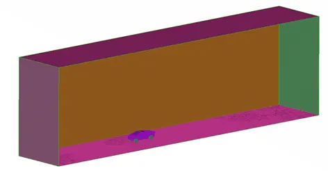
Project 1 : CFD Meshing for Tesla Cyber Truck
LINK TO ANSA FILE: CYBERTRUCK WIND TUNNEL
OBJECTIVE
Perform geometrical cleanup after performing geometry check for multiple checks & rectify them to ensure a close surface for performing a CFD meshing using specified element size. The nature of the element shape should be TRIA element.
Specified Element Size
|
COMPONENTS |
Target Size in mm |
Minimum Size in mm |
Maximum Size in mm |
|
Body |
3 |
1 |
2 |
|
Rims and Tyres |
5 |
3 |
6 |
GEOMETRY
Below is the CAD model required for preprocessing. This model is in a raw state where a lot of faces are missing. There also exist multiple single cons which ensure that the geometry is not close. The figure below is in PID-TOPO mode which shows a clear scope of geometry cleanup. There is also a lot of glitching which shows that there are multiple surfaces that are overlapping over each other.
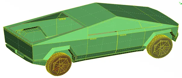
We can clearly observe multiple double & triple cons. We have to rectify every single & triple con. Single cons will result in the open loop which is useless for CFD meshing. We must need a close loop. Tripple cons may result in extra volume which will be trouble during volume mesh.
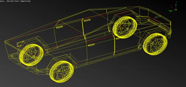
The below figure shows only single & triple cons which are to be repaired.
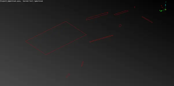
GEOMETRY CLEANUP
The below images shows that geometry has been repaired by inserting missing faces. This also results in the removal of all single cons because there are no red color lines that represent single cons. This is a closed surface and after assigning PID it is in a condition to be mesh. Wireframe mode has been shown to confirm the removal of all single cons ensuring a closed surface.
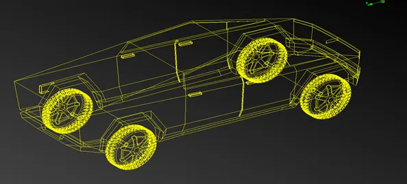
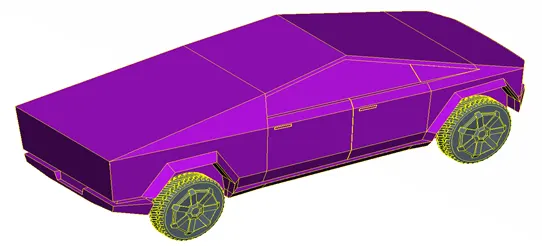
As discussed earlier half of the model will be rectified & we will take a mirror image. We can see the PID mode of the half body part in the below figure. All errors have been rectified which resulted in only double cons as shown above.
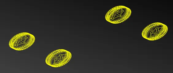
Tyre can be seen in the below figure after the cleanup operation. All single cons & triple cons have been removed along with open faces. We can see only double cons in wireframe mode. This is proof of our cad model is ready for meshing. The image on the left side shows a meshed view of tyre. The target length was 5 mm. Every element was checked for failure & remeshing has been done. We have removed every off element to increase the mesh quality which has been shown below.
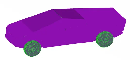
Now figure below shows full-body mesh after taking a mirror image about the symmetric plane. The figure below shows all parts of the car in one image. We can clearly observe different PIDs for different parts. Now we can move for the generation of wind tunnels & volumetric meshing.
After meshing the fill surface we can proceed with wind tunnel creation. The wind tunnel dimensions are shown in the table.
|
Surface |
Distance in mm |
|
Reference Point |
5960 (X) |
|
Front surface |
23840 (4X) |
|
Back surface |
35760 (6X) |
|
Top surface |
17880 (3X) |
The complete wind tunnel alongwith the car model after volume extraction has been shown in the model.