Project 1 : CFD Meshing for Tesla Cyber Truck
AIM :
The aim of the project is to pre-process the tesla cyber truck and mesh it. The CAD model of which can be found here.
OBJECTIVES :
For the given model, check and solve all geometrical error and assign appropriate PID's. Perform meshing with the suitable Target length and element criteria.
PROCEDURE:
We start with importing the file.
The geometry is filled with single cons to eliminate these we use the Topo option.
Before we get into TOPO cleaning procedure , we have to slice the geometry into two in their symmetrical plane, since they are symmetrical in nature also.
On completing all the procedures in one half of the model, we can make a copy of the component into the other easily at last.

Use the delete option to delete one-half of the model.
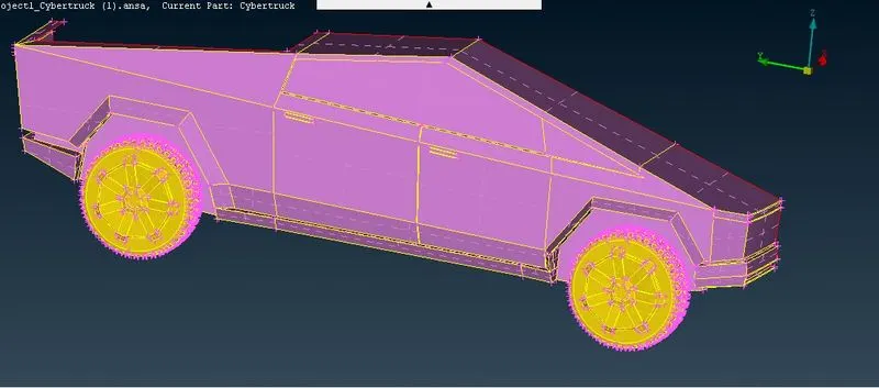
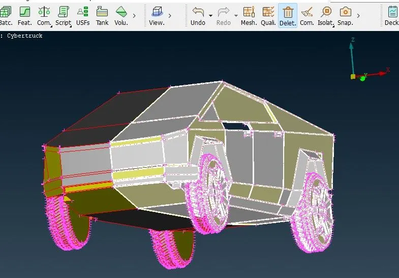
As we see the model given has many single cons, we want to do some geometry checks to explore what are the error we are encountering here.
After completed with the TOPO clean up the geometry is shown given below,
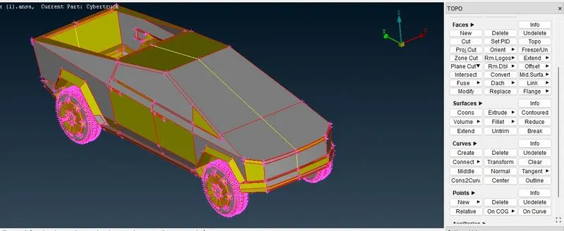
After this step, we are flagging the appropriate boundaries to the respective regions as given below ,
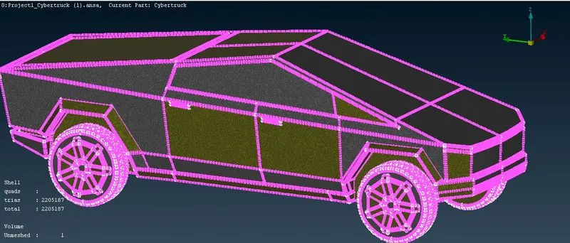
After this, giving the boundaries meshing the geometry with the given mesh lengths.
The meshed geometry is shown in the picture below ,
Onces the mesh is generated on all the regions of the truck, we can now generate the complete truck model.
This is done by the use of symmetry option.
Transform -> copy --> entities --> symmetry--> mirror 3 point plane, then select any 3 points on the symmetric plane.
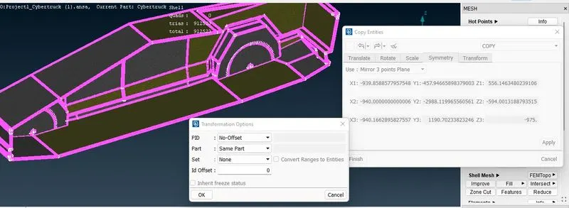
Once this is done, all the entities will get copied to the otherside of the symmetric plane.
# Create PID's
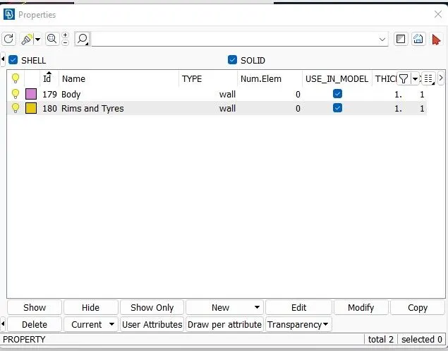
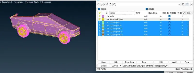
# Use Command tool to eliminate unwanted surfaces/bodies
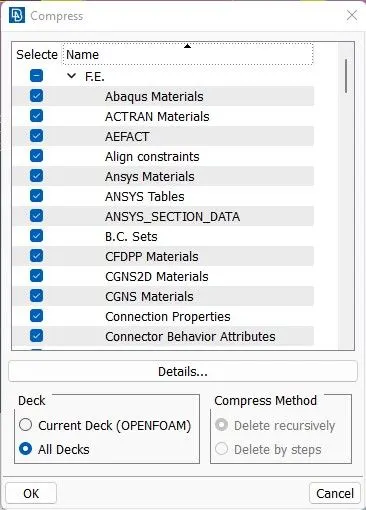
Onces this is done the truck geometry must be enclosed in a box to perform external aerodynamic simulations. If the lengths of the car is 'L' meters then , the virtual wind tunnel dimesions are as follows :-
a. Distance from the wind tunnel inlet to the fornt of the truck = 4L
b. Distance from the wind tunnel inlet to the fornt of the truck = 4L
c. Distance from the sides of the truck to its respective wind tunnel sides = L
d. Distance from the floor to the top surface of the wind tunnel = 3L
The virtual wind tunnel is created by first, identifying the origin of the global coordinates system,then the location of the wind tunnel floor corners is calculated and points created, these points are joined with curves.
A face can be created from these curves. To get top surface of the wind tunnel, a copy of this face is offset at a distance of 3L
The side faces and the inlet and outlet of the wind tunnel can be created by using the reference of the wind tunnel top surface and floor cons.
Now a surface mesh must be generated on the wind tunnel surface.
Since we want finer volume mesh near the surface of the car, which is resting on the floor of the wind tunnel, we must provide a smaller mesh size for the wind tunnel floor and larger mesh size on the wind tunnel top surface.
The mesh size on the sidewalls and the inlet and the outlet of the wind tunnel must increase gradually from the floor to the top surface of the wind tunnel.
To achieve the first the wind tunnel floor and top surfaces are meshed seperately with 'Tria' mesh elements and the mesh target length of 100mm and 200mm respectively.
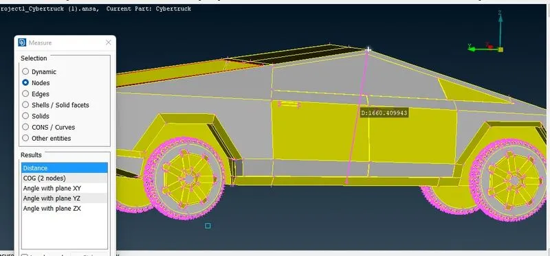
# Total length of Tesla truck(Body)
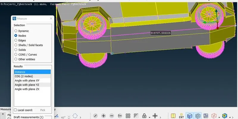
# Distance between top and bottom part of the body
 \
\
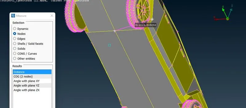
#Distance b/w relative pt. and one side of the body
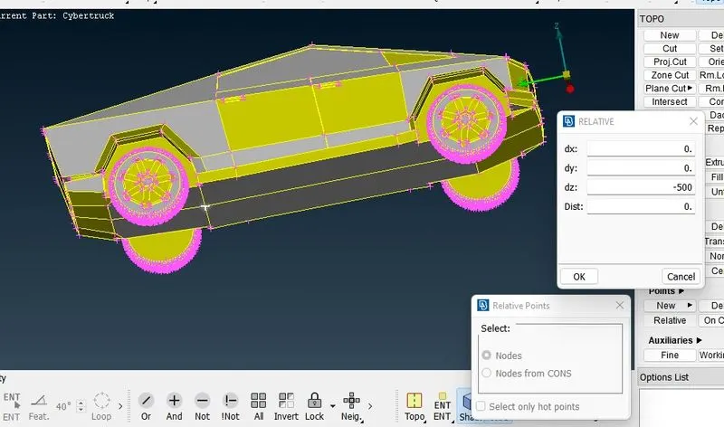
(Create relative point at bottom at a distance of 500)
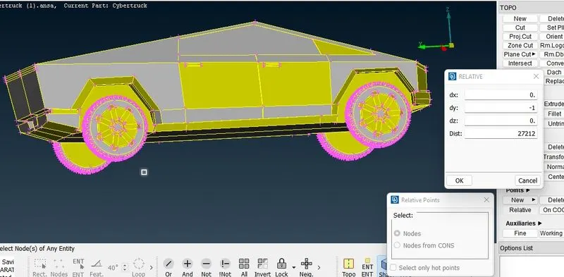
(Create point at front)
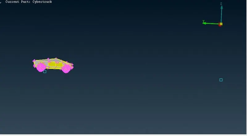
(Front point created )
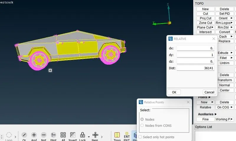
(Create point at Rear)
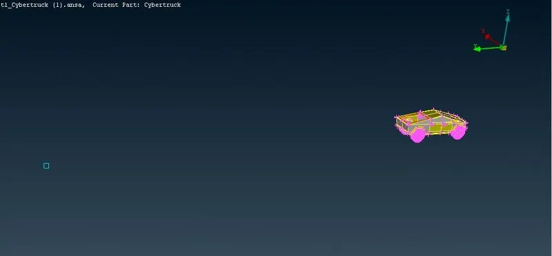
(Rear point created )
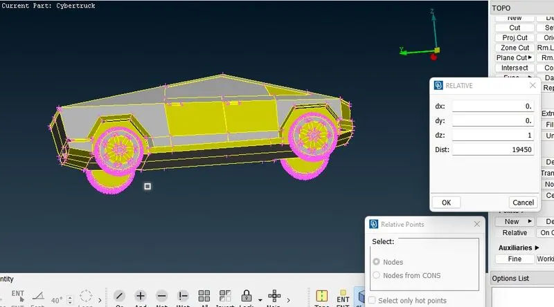
(Create point on Top)
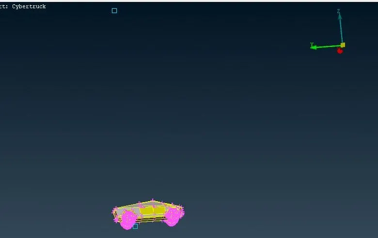
(Top point created )
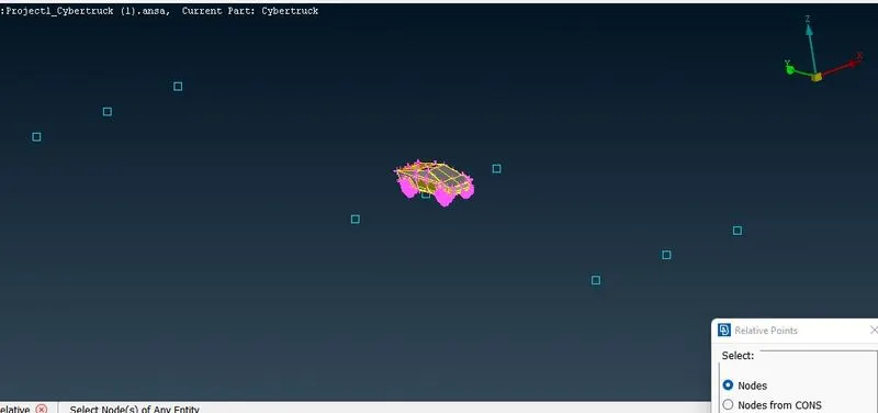
(Create point on both sided)
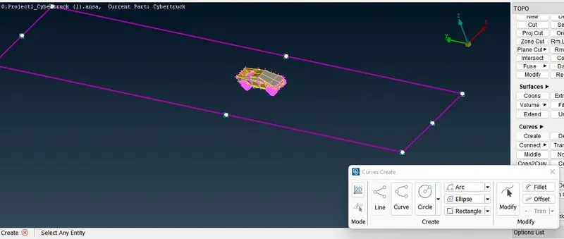
(Create curves on points)
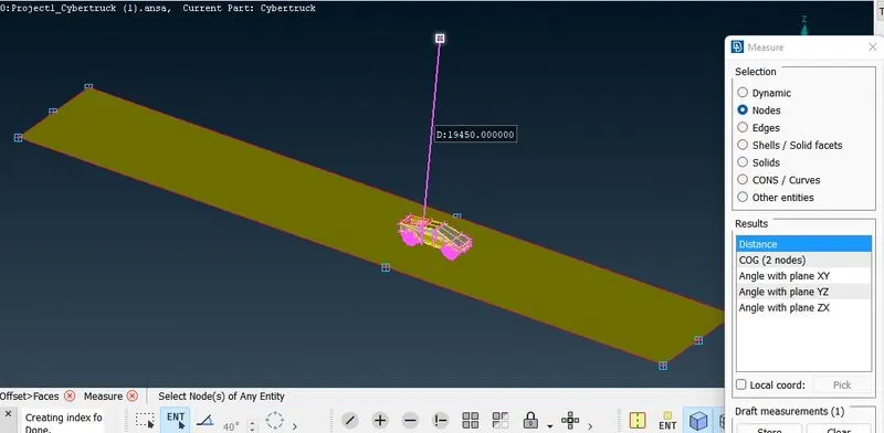
(Measure distance betweem below surface & Top surface)
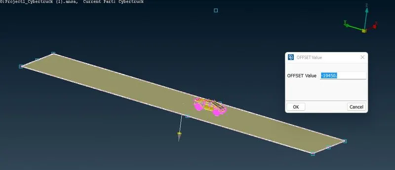
( perform offset)
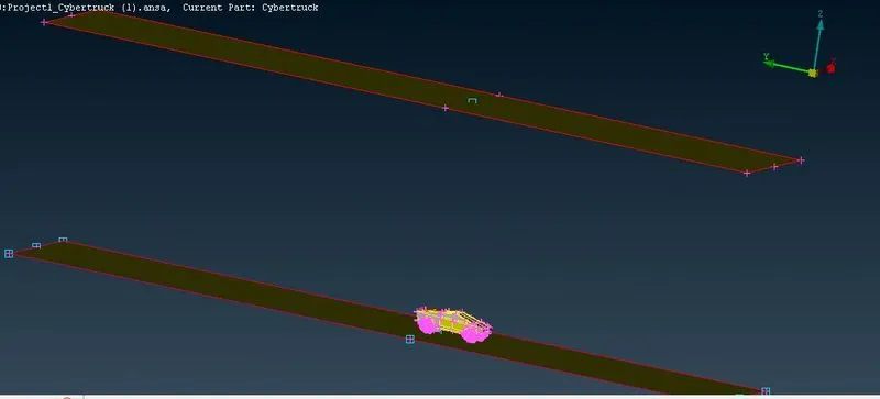
(Done with offset)
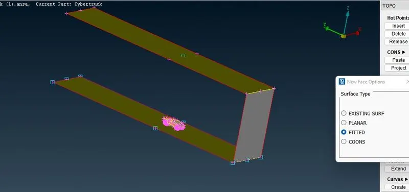
(Created surfaces one by one)
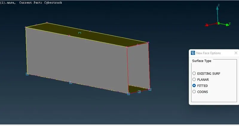
(make hole after filling all the surfaces)
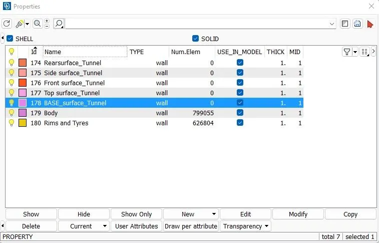
(PID's created after creating all surafces)
# Apply Space command
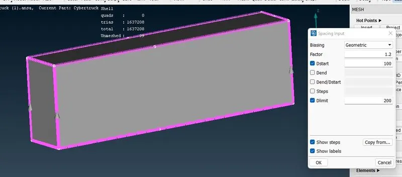
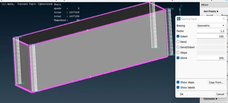
Now, to mesh the other faces in a gradually increasing manner, go to
Mesh -> perimeters -> spacing, select the 4 edges , take baising as geometric (1.1), and dmin = 100, dlimit = 200.
Next, mesh the geometry using spot mesh, and check for quality criteria error if any. if there are many errors, it can be rectified mesh -> shell mesh -> reconstruct.
Once the surface mesh is generated on all the components, the volumetric mesh can be created.
In volume mesh -> define ->auto-detect -> whole data base.
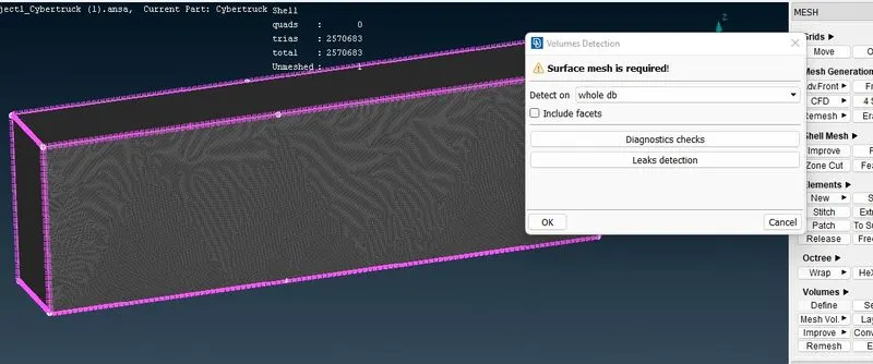
(volume detection)
Here, delete all the unwanted components, i.e the volume enclosed by the solid surfaces.
Now right click on the fluid volume detected and click on re-mesh using data CFD mesh, and the required mesh will be generated.
LEARNING OUTCOMES :
In this process of working on this project we have learned how to
Identifying & cleanup of the topological / geometry error.
Geometry check-up and setting-up of relevent PID's and defining the element size or length.
Setting the mesh parameters and quality criteria, selection of meshing type and generating surface mesh of the CAD model.
Use Quality criteria tool & also learnt various options under the shell parameters such as skewness, min length, max length, max angle and min. angle etc.
Resolving the error such as skewness, min & max lengths using various tools.
Set-up Wind Tunnel as per given dimensions for external flow CFD analysis and surface mesh of wind tunnel.
CONCLUSION :
The imported CAD model for Tesla cyber truck iss Topologically Cleaned & Corrected all the feasible surface error to perform external aerodynamic analysis.
Surface mesh generated with the required element size.
Reconstructed the mesh as per the mesh quality required at Corners & at the Intersection of edges.
Worked with the errors occured in the Mesh.
Created a wind tunnel for exteranl aerodynamic analysis.
A total of 2702847 #2D elements have been generated . This is huge number of elements and is not ideal in most cases hence the mesh size will be adjusted to get the optimal trade-off between the mesh size and the number of elements. The generation of 3D elements for this model requires huge power resources and time. Hence the volumetric meshing of this model can't be done in this project. Also one thing more i used the mesh size of 100 and 200 instead of 20 and 100 beacuse its legging my System several time.
The final result of this project can be found here.
File of Google drive link for this challenge :
https://drive.google.com/file/d/1rcUgoUMPIDM-WhSkYsXgtJyQHUoM5JHT/view?usp=sharing